Language selection

Search

Patent 2096740 Summary

Third-party information liability

Some of the information on this Web page has been provided by external sources. The Government of Canada is not responsible for the accuracy, reliability or currency of the information supplied by external sources. Users wishing to rely upon this information should consult directly with the source of the information. Content provided by external sources is not subject to official languages, privacy and accessibility requirements.

Claims and Abstract availability

Any discrepancies in the text and image of the Claims and Abstract are due to differing posting times. Text of the Claims and Abstract are posted:

  • At the time the application is open to public inspection;
  • At the time of issue of the patent (grant).
(12) Patent Application: (11) CA 2096740
(54) English Title: HYDRAULIC CYLINDER WITH PRESSURE TRANSMITTING PISTON BODY
(54) French Title: CYLINDRE HYDRAULIQUE EN FORME DE POT
Status: Deemed Abandoned and Beyond the Period of Reinstatement - Pending Response to Notice of Disregarded Communication
Bibliographic Data
(51) International Patent Classification (IPC):
  • F16J 10/02 (2006.01)
  • E01D 19/04 (2006.01)
(72) Inventors :
  • WOLFF, GEORG (Austria)
(73) Owners :
  • REISNER & WOLFF ENGINEERING GESELLSCHAFT M.B.H. & CO. KG
(71) Applicants :
  • REISNER & WOLFF ENGINEERING GESELLSCHAFT M.B.H. & CO. KG (Austria)
(74) Agent: SMART & BIGGAR LP
(74) Associate agent:
(45) Issued:
(86) PCT Filing Date: 1991-11-21
(87) Open to Public Inspection: 1992-06-11
Examination requested: 1998-07-17
Availability of licence: N/A
Dedicated to the Public: N/A
(25) Language of filing: English

Patent Cooperation Treaty (PCT): Yes
(86) PCT Filing Number: PCT/AT1991/000119
(87) International Publication Number: WO 1992009748
(85) National Entry: 1993-05-20

(30) Application Priority Data:
Application No. Country/Territory Date
A 2358/90 (Austria) 1990-11-21

Abstracts

English Abstract


- 7 -
ABSTRACT
POTLIKE HYDRAULIC CYLINDER
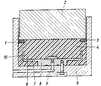
A potlike hydraulic cylinder consists of a cy-
linder pot (1), a piston (2), which constitutes a cover for
the pot, a rubber-elastic plastic body (4), which occupies
the pressure space between the cylinder pot (1) and the pis-
ton (2) and which forms a closed packet (6) that is provided
with a partition (7), which is substantially parallel to the
bottom and constitutes the bottom of the pocket and is con-
nected to at least one bottom extension (8) of the cylinder
pot (1), which extension protrudes axially into the plastic
body (4), and at least one pressure line (9) for a hydraulic
fluid, which pressure line extends through the bottom exten-
sion (8) and the partition (7) and opens into the pocket (6).
To ensure desirable operating conditions, the partition (7)
is adjoined by a peripheral wall (10), which protrudes toward
the piston (2).
(Figure 1).


Claims

Note: Claims are shown in the official language in which they were submitted.

File Reference PCT/AT 91/00119 (24 077)II/Wa
New Claim 1
CLAIMS
1. Potlike hydraulic cylinder comprising a cy-
linder pot (1), a piston (2), which constitutes a cover for
the pot, a rubber-elastic plastic body (4), which occupies
the pressure space between the cylinder pot (1) and the
piston (2) and which forms a closed pocket (6) that is pro-
vided with a partition (7), which is substantially parallel
to the bottom and constitutes the bottom of the pocket and
is connected to at least one bottom extension (8) of the cy-
linder pot (1), which extension protrudes axially into the
plastic body (4), and at least one pressure line (9) for
hydraulic fluid, which pressure line extends through the bot-
tom extension (8) and the partition (7) and opens into the
pocket (6), characterized in that the partition (7) is ad-
joined by a peripheral wall (10), which proturdes toward the
piston (2) and defines with the pot wall a guiding gap for
the deformation of the plastic body (4).
2. A potlike hydraulic cylinder according to
claim 1, characterized in that the peripheral wall (10) con-
sists of a raised rim portion of the partition (7).

Description

Note: Descriptions are shown in the official language in which they were submitted.


2 ~
Engll~h Transl~tlon of International ~ppllcatlon PCT/AT/00119
POTLIKE HVDRAULIC CYLINDER
This inventian relatea to a potlike hydraulic
cylinder comorisinn a cylinder pot, a pistan, l~hich consti-
tutes a cover far the oot, a rubber-elastic plastic bodv~
which occupies the pressure soace ~etween the cylin~er ont
and the oiston an~ which farms a closed oocket that i9 oro-
vided with a aartitian, ~,Jhich i9 substantially parallel to
the bottam and canstitutes the bottom aF the pOcket an~ is
connected to at least one bottom extension o~ the cyl~nder
pot, which extension protrudes axially inta the plastic bo~y,
~t least nne pressure line for a hydraulic fluid, which pres-
~ure line extends throuqh the hattom extensian ann the parti-
tion and opens into the pocket.
Il!hen csnventional hy~raulic cylinders are em~
ploye~ to apply or take up strong pressure ~arces by which
the ~y~raulic cylin~er is sub~ecte~ to a tiltin~ moment, it
is nec~s~ary to in~ert expena~ive oressure-transmitting sphe-
rical cansa into the hy~raullc cylin~er in nr~er to relieve
it from tiltinn moments. The ~eal IlJhich i~ required between
the cylin~er ~all an~ the Piston oF the hydraulic cylin~er
preclu~es the pravision of a substantial quid~n~ oap, which
~aul~ be necessary to permlt a tilt.in~ oF the Piston. Pe~i~es,
a Dlastlc ~eformation of the cylin~er oall is not per~isaible
even in local regions ir the sealln~ element is nat to he en-
~annere~. For th1S reasan rel2tlvely lana pistons are use~
to take u~ the lateral For~ea an~ substantiallv lncreasD the
averall heiqht. Annther renuiremPnt to be met by such ny~rao-
lic cylio~er~ rnsi~es in ;hat they ~houl~l be ma~e From a ~a-
terial l,~hich has a relati\iely e~all elastlc elonaation an~
a lol,l coPfFiClent of e~oansion 50 that thn qui~inn naP -aetwuen

- 2 - ~ 7 ~ ~
the piston and the cylinder w811 cannot b~ ex~unded to an
extent which would endanger the sealing element under a
hlgh loudO
In or~er tn avoid said disadvantages it is
kno~n from pot-shaped bearings, particularly iF they are
use~ in bridges ~2rman Patent SpeciFication 3,410,~75), to
~ill the space between the cylinder Pot and the piston,
L~hich constitutes a cover For the oot, by a ruhber-elastic
plastic ba~y, L~hich usLJally cansists of an elastomer an~
L~hich per~its the provisian between the pot ~all and the
piston of a guiding gap which i5 suFficiently large to per-
mit a tilting oF the piston relative to the cyl~nder pot
whereas a sealing of said gui~inq gap against an extrusion
oF plastic need not he feare~. Such a ootli~e bearing is
supplied ~ith a hydraulic ~'luio, ~hich is forced into a
closed pocket provi~ed within the olastic boùv so that the
latt~r owing to its incompressibility is dis~laced against
the pi3ton to ralse the latter and the pocket is expandeo.
That poc~et is closed at its bottom by a Partition, ~hich
i~ joined to a bottom extenslon of the clvinder pot. ~dja-
cent to the inlet for thz hy~raulic fluid a pressure line
extends thoruqb the extension. That partition is intended to
permit a hydraulic cushion to be formed under a pressure
which 1~ uniformly ~istributeo throughout the surface area
of the partition so that the olastic body disposed over the
partition w~ll uniFormly he raised. ~ut it has been Found in
practice that under high hydraulic pressures the partition
will be pulle~ aut nf the oocket of the plastic bod~ or the
piston seal will be pulled From the oiston because the ~e-
formation oF the rubbPr-elastic nl3stic bo~t cannot be ccn-
trolle~. rOr thi~ rnason ~he ~el~ of apoliration nf swch
potlike bearings is restricte~i a1though they are ~esirable
as regarris tbe taking up o~ tiltinq muments and lat_ral Forces
and are insusceptible to an L?longatinn oF materials.

-- 3 --
2~9 ~ 7 l~ ~
For this reason lt i3 an ~bject of the lnven-
tion to a~ovide a patllkD hydraulic cylinder whlch is of
the kind de~cribed F~rst hereinbefore and i~ so imDrnved
by the provisian of a simple means that the advantages af-
fnr~ed bV the use af a rubber-el3stic olastlc body can fully
be utilized but the ~isad~antages in\/ol~ed in an uncontroll~ad
deformation of the plastic ~ody ~.lill be avoi~ed.
The object set forth is acco~nlishe~ in acenr-
dance ~ith the invention that the partition is adJoined 5y
a peripheral wall, which orotrudes toward the ~iston.
~ s a result, a guidinq gap far the ~efor~ation
of the plastic body ls ~efine~ bEtween the ~ot wall and the
oeripheral wall which ad~oins the oartiti~n so that the por-
tlon in whieh the plastic body is essentially de~ormable is
strueturally deFine~. Pecause the de~nr~ation of the rubber-
elastic plastie body is thus rastricte~ to a Portion of its
periphery a pressure applied cannot cause the poeket of the
plastie body to be ~ulled fro~ the partitian or an extrusion
oF a portion of the Dlastic body between the piston and the
oistan seal. Fnr this rPason the ~asure adoDt2~ in accordance
with the inventlnn has the result that the notlike h\ydraulie
eylinder-piston assembly has a hiqh Functional reliability
and ~uring a draininq o~ the hydraulie flui~ Fro~ the pocket
of the plastic bo~y the pistan will return to its initial
position withnut ~ifFiculty because the defol~atian af the
plastle body is restricted to a oortion o~ its periDhery eY-
tending alan~ thz pot wall so that the pocket oF the plastic
body can readily be closed as that nortlon of the plastie hody
whieh is a~jacent to the piston descends toward the ~artition.
It i9 3aDarent t~at thP peri~heral wall !llhich
adjo~ns the oartitinn canstitutes a ~uidinn wall fnr the rle_
for~ation nf t.hn Dlastic hodv. For this reasan th3t ~,Jall ~ust
.

- 4 -
have a ~ufficiently lurge height, whic~ must bP selected
in dependence on the condltians in each case~ To permit
the peripheral well to perfor~ it~ guiding Functions, an
adhering of thst wall to the plastic bady must be Prevented.
~he wall itselF may have any of widely difFerent designs,
provided that it is ensured that the wall oefines the re-
qion in which the plastic body is deFQrmable. A particular-
ly simple design will be obtained if` the peripheral wall
consists of a raised rim portion of the partition.
The subject matter oF the application is shown
by way of example in the drawing, in which
Figure 1 is a schematic axial sectional view
showing a DotlikP hydraulic cylinder in accordaoce with the
in~ention when it i5 not being suoplied with hydraulic fluid
and
Figure Z is a ~iew which i5 similar to Figure 1
and shows the hydraulic cylinder as it is supplied with hy-
draulic fluid.
The illustrated patlike hydraulic cyllnder essen-
tially consists nf a cylinder pot 1 and a piston 2, which
cùnstitutes a cover for the pot and carries a pi~t~n seal 3,
which ad~oins the wall of the pot, The pres~ure space defin~d
between the cylinder p~t 1 and the piston Z is occuDied by R
rubber-elastic plastic body 4, which at a distance from the
bottom 5 of the not Forms a pocket ~.~, which ls parallel to
the hottom and in which a partitian 7, which is parallel ta
the bottom, is insert2d as the bottom nf th~ pocket. That Par-
tition 7 i5 int2gr311y connecte~ to a bottom extension ~R,
which axially nrotrudes into the Plastic ~ody 4 an~ t~rouqh
which a i~ressure llne ~ Fnr a hydr~ulic Flui~ extenos, which
.
,
', ' `:
. ' ' ' :
, ' ~ ' ' .' ' . '

_ 5 ~ rlL~
line opens lnto the pocket ~. A dif~erence from known pat-
like besrings of that kind realdes in that the partition 7
is provided with a peripheral wall 10, which adJoins on the
outside and which in the illustrative embodiment consists
af a raiqed rim pcrtion of the partition 7. That peripheral
wall 10 does not adhere to the plastic body 4 and separates
from the remaining Dlasti- body a peripheral portion, which
during a supply of hydraulic fluirl to the hydraulic cylinder
i5 subjected to the substantial deformation, as is shawn in
Figure 2.
The hydraulic fluid which is forced into the
pocket S then exPands the pocket and ahove the partition 7
constitutes a hydraulic Fluid cushion, which i9 essentially
defined hy the peripheral wall 10 anr! hy which that portion
of the plastic hody which i_ adjacent ta the oody and, as a
result, the niston Z are raiserl. ~s is also apparent from
Figure ~ the restrictiun of the deformation Df ihe plastis
body to a peripheral portion prevents a rleformation of the
pla~tic hody which would ad~ersely affect the descent of the
piston ~ 50 that the initial oosition ahown in Fi~ure 1 will
be assumed when the hydraulic fluid has oeen drained.

Representative Drawing
A single figure which represents the drawing illustrating the invention.
Administrative Status

2024-08-01:As part of the Next Generation Patents (NGP) transition, the Canadian Patents Database (CPD) now contains a more detailed Event History, which replicates the Event Log of our new back-office solution.

Please note that "Inactive:" events refers to events no longer in use in our new back-office solution.

For a clearer understanding of the status of the application/patent presented on this page, the site Disclaimer , as well as the definitions for Patent , Event History , Maintenance Fee  and Payment History  should be consulted.

Event History

Description Date
Inactive: Dead - Final fee not paid 2003-06-06
Application Not Reinstated by Deadline 2003-06-06
Deemed Abandoned - Failure to Respond to Maintenance Fee Notice 2002-11-21
Deemed Abandoned - Conditions for Grant Determined Not Compliant 2002-06-06
Letter Sent 2001-12-06
Notice of Allowance is Issued 2001-12-06
Inactive: Approved for allowance (AFA) 2001-11-22
Inactive: Adhoc Request Documented 2001-09-05
Inactive: Delete abandonment 2001-09-05
Inactive: Abandoned - No reply to s.30(2) Rules requisition 2001-06-07
Amendment Received - Voluntary Amendment 2001-06-07
Inactive: Correspondence - Formalities 2001-06-07
Inactive: S.30(2) Rules - Examiner requisition 2000-12-07
Inactive: First IPC assigned 1998-10-26
Inactive: IPC assigned 1998-10-26
Inactive: RFE acknowledged - Prior art enquiry 1998-08-28
Inactive: Application prosecuted on TS as of Log entry date 1998-08-25
Inactive: Status info is complete as of Log entry date 1998-08-25
All Requirements for Examination Determined Compliant 1998-07-17
Request for Examination Requirements Determined Compliant 1998-07-17
Application Published (Open to Public Inspection) 1992-06-11

Abandonment History

Abandonment Date Reason Reinstatement Date
2002-11-21
2002-06-06

Maintenance Fee

The last payment was received on 2001-07-12

Note : If the full payment has not been received on or before the date indicated, a further fee may be required which may be one of the following

  • the reinstatement fee;
  • the late payment fee; or
  • additional fee to reverse deemed expiry.

Please refer to the CIPO Patent Fees web page to see all current fee amounts.

Fee History

Fee Type Anniversary Year Due Date Paid Date
MF (application, 6th anniv.) - standard 06 1997-11-21 1997-11-21
Request for examination - standard 1998-07-17
MF (application, 7th anniv.) - standard 07 1998-11-23 1998-11-23
MF (application, 8th anniv.) - standard 08 1999-11-22 1999-10-13
MF (application, 9th anniv.) - standard 09 2000-11-21 2000-10-27
MF (application, 10th anniv.) - standard 10 2001-11-21 2001-07-12
Owners on Record

Note: Records showing the ownership history in alphabetical order.

Current Owners on Record
REISNER & WOLFF ENGINEERING GESELLSCHAFT M.B.H. & CO. KG
Past Owners on Record
GEORG WOLFF
Past Owners that do not appear in the "Owners on Record" listing will appear in other documentation within the application.
Documents

To view selected files, please enter reCAPTCHA code :


To view images, click a link in the Document Description column. To download the documents, select one or more checkboxes in the first column and then click the "Download Selected in PDF format (Zip Archive)" or the "Download Selected as Single PDF" button.

List of published and non-published patent-specific documents on the CPD .

If you have any difficulty accessing content, you can call the Client Service Centre at 1-866-997-1936 or send them an e-mail at CIPO Client Service Centre.


Document
Description 
Date
(yyyy-mm-dd) 
Number of pages   Size of Image (KB) 
Representative drawing 2001-07-30 1 32
Abstract 1994-04-01 1 24
Cover Page 1994-04-01 1 20
Claims 1994-04-01 1 26
Description 1994-04-01 5 178
Abstract 2001-06-07 1 23
Description 2001-06-07 5 178
Claims 2001-06-07 1 37
Drawings 1994-04-01 2 85
Reminder - Request for Examination 1998-07-22 1 129
Acknowledgement of Request for Examination 1998-08-28 1 177
Commissioner's Notice - Application Found Allowable 2001-12-06 1 166
Courtesy - Abandonment Letter (NOA) 2002-08-15 1 170
Courtesy - Abandonment Letter (Maintenance Fee) 2002-12-19 1 176
International preliminary examination report 1993-05-20 18 693
Correspondence 2001-06-07 2 98
Fees 1998-11-23 1 43
Fees 1997-11-21 1 37
Fees 1996-10-22 1 56
Fees 1995-11-06 1 45
Fees 1993-05-20 1 35
Fees 1994-11-14 1 41