Note: Descriptions are shown in the official language in which they were submitted.
i s
CA 02097319 2002-06-04
-1-
SINGLE CAMERA AUTOSTEREOSCOPIC IMAGING SYSTEM
TECHNICAL FIELD
This invention relates to stereoscopic imaging systems
for creating a three-dimensional illusion using motion
pictures or video recorders. It is more closely related to
autostereoscopic systems, which produce true three-
dimensional images which do not require glasses or parallax
barriers to create a three-dimensional illusion.
BACKGROUND ART
Humans perceive movement in motion pictures and
television because of the brain mechanisms underlying such
established psychological facts as persistence of vision and
the phiphenomenon. Depth is perceived by the interpretation
of disparity information from the eyes through a process
called stereopsis. What stereopsis is and how it is performed
are still a matter of some debate.
Humans have binocular (stereoscopic) vision-two eyes
that look in the same direction and whose visual fields
overlap. The eyes are horizontally aligned and separated by
an interocular distance averaging about 65mm. Each eye views
the scene from a slightly different angle. The scene viewed
is focused by the eye's lens onto the retina as a two-
dimensional image. The two-dimensional images from each eye
are transmitted along the optic nerves to the brain's visual
cortex. The monocular and parallax depth information from the
eyes is compared and interpreted through stereopsis, to form
a true three-dimensional view.
A distinction must be made between monocular depth cues
and parallax information in the visual information received.
Both eyes provide essentially the same monocular depth cues,
WO 92/09922 PCT/US91 /08868
-2-
but each provides different parallax depth information, a
difference that is essential to produce a true
three-dimensional view.
It is possible to perceive depth to a certain extent in
a two-dimensional image. Monocular depth is perceived when
viewing a still photograph, a painting, or standard television
and movies, or when looking at a scene with one eye closed. It
is perceived without the benefit of binocular parallax depth
information. Such depth relations are interpreted by the
to brain from monocular depth cues such as relative size,
overlapping, perspective, and shading
Even though human eyes are horizontally aligned, the
brain will process parallax information from any direction.
It has been reported that vertical parallax information when
displayed at a rate of 4 to 30 Hz, produces a sense of depth
that is superior to that produced by horizontal parallax
presented in the same manner.
It has also been reported that the fusion range of
stereoscopic vision is within a 40 minutes ( . 66°) angle for
horizontal disparity and up to a 7 minutes (.1166°) angle for
vertical disparity.
Parallax information does not have to be presented to the
brain simultaneously. The left and right eye depth
information can be presented alternately to the left and right
eyes, resulting in depth perception as long as the time
interval does not exceed 100 milliseconds. The brain can
extract parallax information from a three-dimensional scene
even when the eyes are alternately covered and uncovered for
periods of up to 100 milliseconds each. The brain can also
accept and process parallax information presented to both eyes
if sequenced properly. The ideal view cycle sequencing rate
is between 3-6 Hz.
True three-dimensional image displays can be divided into
two main categories, stereoscopic or binocular and
autostereoscopic. Stereoscopic techniques (including
WO 92/09922 ~ ~ ~ ~ ~ ~ .~ PCT/US91 /08868
--3-
stereoscopes, polarization, anaglyphic, Pulfrich, and
shuttering technologies) require the viewer to wear a viewing
apparatus. Autostereoscopic techniques (such as holography,
lenticular screens, parallax barriers, alternating pairs, and
parallax scans) produce images with a true three-dimensional
illusion without the use of glasses.
Prior art three-dimensional television or motion picture
display system, that did not require viewing glasses,
alternately displayed views of a scene recorded by two cameras
at their respective points of view. U.S. patent 4,006,291 to
Imsand, U.S. patents 4,303,31Ei and 4,420,230 to McElveen, and
U.S. patent 4,429,328 to Jones, et al describe methods using
horizontally, vertically and a combination of horizontally and
vertically displaced views. The images produced using the
method of Jones, et al did appear three-dimensional, but were
extremely unstable and possessed a distracting rocking motion.
Jones, in U.S. patent 4,528,587, attempted to control the
rocking motion by using a video mixing device, which
intermittently superimposed t:he second camera's image onto
that of the first, rather than alternating images as before.
This mixing technique did little to control rocking and
resulted in intermittent image. softening.
The applicants have experimented with the known
alternating-camera methods and concluded that stable
three-dimensional images could not be achieved simply by
aligning two cameras vertically, horizontally or diagonally
and switching between or mixing them at a 4 to 5 Hz view cycle
rate. Commercial production standards today are much too
high for the image instability and/or softening inherent in
these methods.
Unlike stereoscopic techniques, which provide each eye
with a different image, alternating techniques provide the
same image to both eyes. With a stereoscopic system the brain
will compensate for some mismatch of camera lenses, color and
luminance differences, and differences in parallax angles. In
alternating systems the slightest mismatch is readily
perceived.
WO 92/09922 ~~ PCT/US91/08868
_4_
Image instability (rocking) is caused by a variety of
factors. The main cause is the presentation of alternating
points of view that differ in parallax and are not in tune to
be perceived as depth rather than motion. Since all prior
art alternating techniques use two cameras, factors such as
improper alignment of cameras, lenses mismatched in focal
length and/or focus, chrominance and luminance mismatches,
poor quality optics, sand ppolarization differences, and
misplaced convergent point all contribute to image
instability. Another problem is the methods used to obtain
the parallax information. Provisions must be made for constant
parallax and convergent corrections during shooting in order
to keep the depth information in tune with the human brain.
Image instability can be rendered less noticeable by the
use of masking techniques. Camera motion is very effective in
hiding rocking, apparently because the brain places less
importance on the rocking motion than on the camera motion.
This result could represent some sort of natural stabilizing
phenomenon or mechanism of the brain that helps us see clearly
when we walk or run, when the images would otherwise bounce.
Proper camera convergence and parallax angle adjustment
are also very important. Our tests have shown that if the
convergent point is set on the closest object to the camera or
closer and the parallax angles are in tune with the scene
being shot, the brain tends to disregard background motion, if
it is combined with camera motion. If the convergent point is
set behind the closest object, that object will rock and the
rocking cannot be masked by camera motion or parallax tuning.
If the camera moves, the closest object moves, or something
enters the frame closer than the convergent point, the
convergent point must be pulled back and the parallax angle
adjusted (tuned) accordingly. The reverse is also true, if
the closet object moves farther away from the camera, the
parallax angle should also be adjusted.
3 5 The methods and camera system described in U . S . patent
numbers 4,815,819 and 4,966,436 to Mayhew and Pritchard
require careful camera alignment to eliminate unwanted
i
CA 02097319 2002-06-04
-5-
movement in all depth planes. Precision matching of
chrominance and luminance between cameras, and a good deal of
operator skill to manipulate disparity, convergence, and
time-displacement rates required to maintain a stable image.
Even though this two camera system can deliver a very
stable, broadcast-quality video image, it is not ideal for
day to day television production. The cameras require
constant alignment adjustment. Because of the folded optical
path, lenses with a view wider than that of a 32mm lens can
not be used, and zoom lenses are not practical. The fact
that the system uses a special mount to hold two cameras and
a folded optical path makes it large and heavy.
For all of the reasons above and others the
autostereoscopic methods using a single camera are the subject
of the applicants U.S. Patent 5,014,126, were developed. The
methods described in said U.S. Patent do not suffer from any
of the matching, alignment, and lens limitations of the prior
art. Other single camera systems have been suggested and some
even developed for three-dimensional imaging, but all use two
lenses or some type of beamsplitter to provide two differing
parallax views. The disclosures of all of the applicants
aforesaid issued or pending.
Most prior art shuttering stereoscopic and
autostereoscopic motion picture and television techniques use
square wave switching methods to alternate between the two
points of view, or origin. The abrupt shift in parallax in
square wave switching contributes to image instability.
The present application approach is to give each frame
its own parallax scan. Each frame and its scan preferably
will fall on one or the other side of the nominal optical
axis of the camera, which is the point of zero amplitude of
the sine wave. The camera imaging plane's optical axis
sweeps across the nominal and through positions having
parallax.
A parallax scan is different from the prior art point of
WO 92/09922 ~ ~ PCT/US91/08868
-6-
view or origin. A typical point of view has the same angle of
parallax at the start and end of a particular frame's
exposure. The angle in radians is determined by the disparity
of the point of origin (distance from the nominal) divided by
the distance to the point of convergence (for angle in degrees
multiply by 57.2958). One point is on one side of the nominal
and one the other. Each point may have several frames exposed
from it, or as few as one field in video.
Parallax scanning techniques employ a continuously moving
l0 imaging plane. A particular frame will start its exposure at
one angle of parallax and end it at another angle of parallax,
which is greater or less than the starting angle depending on
where the frame lies in the scan. A parallax scan can sweep
back and forth across the nominal zero point in any
direction-horizontal, diagonal or vertical. The scanning
motion blurs the background of the frame slightly and
therefore helps mask unwanted rocking. The optical axis of
the parallax scan is centered on the point of convergence. A
parallax scan can achieve a very large angle of parallax in
its extreme exposure frame and a high overall average angle of
parallax. Because the differences are slight, a sine wave can
also be approximated by a parabolic sequence.
It is an object of this invention to provide a recording
system for producing the scanning motion which produces the
time-shared imagery.
Another object of this invention is to provide a system
for moving the scanning components without introducing
reaction forces (vibration) in the recorder and its supporting
members.
Still another object of this invention is to provide
inexpensive scanning techniques suitable for less demanding
situations.
An even further object of this invention is to provide a
disparity control system which is locked to the camera frames
or fields.
A still further object of this invention is to provide a
disparity control responsive to the scene velocity.
WO 92/09922 ~ 9 ~ ~ ~ PCT/US91/08868
Another object of this invention is to provide automatic
adjustment of the scanning convergent point.
DISCLOSURE OF INVENTION
These and other objects are achieved by providing an
autostereoscopic image recorder having a single recorder for
recording images and including a single optical path through
a convergent point between the scene and the recorder, a
scanning path structure anc~ a driver for substantially
continuously moving the single optical path along a scanning
path for a plurality of scanning cycles. The path defining
structure may include a rail transverse to the optical path
and a second rail displaced from the optical path at an angle
to the first rail. The recorder is mounted to move on the
rails. The convergent point of the system may be adjusted by
moving the recorder and the rail system relative to each
other. This may be achieved) by moving the rail structure
along the optical path or changing the angle of the second or
convergent rail. A path defining structure may define a
linear path orthogonal to the optical path and include a lens
which converges the optical path on the convergent point.
Alternatively, the path defining structure may define an arc
which is centered about a fixed point in the optical point and
the lens for causing the optical path to intersect the second
fixed point. The convergent point is one of the first or
second fixed points. In either system, the convergent point
may be adjusted by changing the distance between the lens and
the recorder or the first f ixead point .
The driving device which produces vibration-free scanning
motion includes a support to which a first and second mass are
movably mounted. The recorder is connected to the first mass.
A drive for the masses substantially continuously moves the
first and second masses in opposite directions such that the
recorder moves along the scanning path for a plurality of
scanning cycles. The second mass has substantially the same
mass as the first mass plus t:he mass of the recorder. The
WO 92/09922 g ,~ t~ PCT/US91/08868
_g_
drive for the masses includes an armature and a stator mounted
to the first and second masses. The first and second masses
are mounted to the support by a pulley structure to produce
the equal and opposite motion.
The convergent point may be adjusted automatically by a
device which determines the distance between the recorder and
a desired convergent point thereby adjusting the scanning path
to maintain the optical path on the desired convergent point
during scanning.
The extent or amplitude of the scanning path is adjusted
depending upon the degree of motion in the scene or of the
apparatus. Because of observed masking techniques, the amount
of travel is increased for the degree of motion. The amount
of motion is determined by correlation between successive
recorded images.
The driver structure is synchronized to the recorder
operation. The synchronization controls the drivers for
bi-directional operation of the recorders such that double
exposure can be produced while maintaining the
three-dimensional effect.
In addition to the parallax effect produced by recording
a plurality of scanning images during a cycle, additional
external stimuli is provided. The position of the recorder
along the scanning path is determined and the ultimate image
is adjusted. The image may be adjusted within the recording
frame or during the display of the recording frame.
Other objects, advantages and novel features of the
present invention will become apparent from the following
detailed description of the invention when considered in
conjunction with the accompanying drawings.
BRIEF DESCRIPTION OF THE DRAWINGS
Figure 1 is the front view of an autostereoscopic camera
incorporating the principles of the present invention;
Figure 2 is the side view of an autostereoscopic camera
of Figure 1;
Figure 3 is the side view of an autostereoscopic camera
WO 92/09922 PCT/US91 /08868
2~a'~3
_a,_
with its components removed t:o expose the convergent rail
system;
Figure 4 is a schematic o:E the convergent motion;
Figure 5 is a block diagram of a convergent point control
system according to the principles of the present invention;
Figure 6 is a side view of a counterbalanced linear motor
for disparity drive which eliminates vibrations according to
the principles of the present .invention;
Figure 7 is a block diagram of a control system for the
l0 disparity motor of Figure 6;
Figure 8 is a block diagram of a scene velocity
measurement system for the automatic controller of Figure 7
according to the principles of the present invention;
Figure 9 is a schematic view of an autostereoscopic
camera system using a cylindrical lens to provide convergence
according to the principles of the present invention;
Figure 9A is a schematic view of an autostereoscopic
camera using a cylindrical lens with adjustable convergence
according to the principles of the present invention;
Figure 10 is a schematic view of an autostereoscopic
camera using a cylindrical :Lens for convergence and an
oscillating cube for disparity according to the principles of
the present invention;
Figure 1l is a top view of the system shown in Figure 10;
Figure 12 is a block diagram of a video system with
display disparity according to the principles of the present
invention;
Figure 13 is a schematic view of a two convergent rail
system according to the principles of the present invention;
3o Figure 14 is a schematic view of a variation of the
embodiment of Figures 1-4; and
Figure 15 is a schematic view of an optical system using
a pair of optical guides.
BEST MODES OF CARRIrfGOUT THE INVENTION
The preferred embodiment for professional film and
television use provides the greatest versatility in disparity
WO 92/09922 ~ ~ ~ ~ ~ '~ ~~ PCT/US91 /08868
-10-
(the extent of the scan) and~convergence (focus or hub of the
scan); both are continuously variable.
This embodiment shows a film camera, however the
technique is equally applicable to television and other motion
imaging techniques. Further, this embodiment shows vertical
scanning however the technique can be applied to horizontal
scanning or a combination of vertical and horizontal scanning
by simply rotating the scanning mechanism. Still further the
linear techniques maybe converted to rotary to produce a
l0 circular or elliptical scanning.
The preferred embodiment is depicted in Figures 1, 2 and
3 in front and side views respectively. The lens 1 is
connected to the camera front 2 by the lens mount 3 and by the
lens support 4 and 5. The camera front 2 supports the
aperture plate 6 and movement 7. The remaining solid
connections to the camera front 2 are the yaw arm 8 and the
convergent arm 9. Elements 1-9 constitute a camera front
assembly 10.
The camera front assembly 10 moves on front rail 1l, rear
rail 12, and convergent rail 13 with aid of linear bearings
such as 14 shown in detail in Figure 3. The linear bearing 14
for rails 11 and 12 are preferably Thompson Industries super
ball bushings which allow for angular misalignment of .009
inch per inch or 9 milliradians of rotation. This is more
than acceptable since the maximum demanded for
autostereoscopic imaging is 2 milliradians.
The rails 11, 12, and 13 are supported by blocks 15 and
16 and by convergent gear 17 respectively. Components 15-17
are supported by the camera frame 18. The camera frame 18
also supports the rear of the camera and is fastened to a pan
and tilt support system (not shown) which supports the camera
system from the side.
The convergent gear 17 is rotatably mounted to camera
front 18 by bearings 21 and driven by motor and gear assembly
22. The position of the convergent gear 17 or angle of
convergent rail 13 is transmitted to a servo positioning
system by feedback sensor 73 of Figure 5 by gear 23. The
WO 92/09922 ~ ~ ~, ~ ~ ~ ~ PCT/US91/08868
-11-
position of the camera front assembly 10 is sensed by sensor
19, which was omitted from Figures 1 and 2 for clarity, and
used in the control circuit of Figure 7.
A linear bearing assembly 24 which includes bearing 14
connects the convergent rail. 13 to and rotates in the
convergent arm 9 on bearings 25. The convergent rail 13 is
moved out of line with rail 11 to make the camera front move
in an approximate arc about a convergent point in front of the
camera.
The scanning motor assembly and camera front assembly 10
are supported by cross arm 31 wlhich is connected to the bottom
of camera frame 18. Support arm 32 is clamped to cross arm 31
with a clamp 33 and bolt 34. Support rail 35 is bolted to
support arm 32 while rail 36 is bolted to lens support 5 via
T-nuts, not shown, in the T-nut slots 5a in lens support 5.
Collars 37 locate the scanning or disparity motor 40 left and
right on rails 35 and 36. The scanning motor 40 may be moved
forward and rearward via the s>upport arm assembly 32-35 and
the rail 36 in conjunction with the aforementioned T-nuts in
lens supports 5.
The scanning motor 40 must be positioned so that its
center of gravity is in line with the center of gravity of the
camera front assembly 10 wherein said line is the direction of
the scan. This is one of tlhe necessary conditions for a
perfectly counterbalanced system, i.e. a system which does not
vibrate the camera or the camera mount.
Briefly, the scanning motor 40 consists of stator 41,
armature 42, frame 43, rollers 44, and belts 45. The stator
41 is a permanent magnet structure which provides reaction
~ mass and the magnetic field to work armature 42. The belts 45
are stretched over pairs of rollers 44. The belts 45 are also
fastened to the armature 42 and stator 41 so that the armature
42 and stator 41 move in opposite directions with respect to
frame 43. The specific attachment is shown in Figure 6.
The total weight of the camera front assembly 10, the
stator 41 and armature 42 are supported by the rollers 44,
motor frame 43, rail 35, etc.
20973 19
-12-
A counterbalanced vibration free system requires that the
stator 41 balances armature 42 and camera front assembly 10
and rail 36. Since the pulley belt system moves the stator 41
and armature.42 equally, the stator 41 must weigh the same as
the components 1-9, 36, 37, and 42. If the stator 41 and
armature 42 move unequally, then the weights must be
different.
The camera rear 51 is supported by camera frame 18. The
camera rear 51 accepts the film magazine 52 and mounts a film
drive motor, not shown. This film drive motor drives the
sprocket 53 and drive shaft 54 via couplings 55. These
couplings are preferably the bellows variety to transmit power
to the movement 7 and shutter, not shown, while allowing for
the varying angle and distan<:e between the camera front 2 and
camera rear 51.
The sides, top, and bottom of the camera can not be
solid, but are a bellows and are used in a manner similar to
the bellows in a view camera.
It is important to isolate the motion from the front of
the camera to the rear because the rear components are heavy
and the film moves in the magazine 52, thereby changing the
weight distribution-.
Figure 4 is a schematic .diagram of the convergent motion.
Lines 61, 62, and 63 represent the axis of rails 11, 12, and
13 respectively. Line 64 is the nominal optical path while
Line 65 is an off nominal optical path separated by angle a at
the at the convergent point t~6. The convergent rail 63 is at
an angle ~ with respect to front rail 61. The distance c is
the distance to the convergent point while d is the distance
from the nominal optical axi:~ 64 to the center of rotation of
the convergent rail 13 and gear 17.
The relationship between the distance c and the angle ~B
is approximately:
c = d cot
This relationship is accurate so long as a is small.
Fortunately, the limit for good autostereoscopic imaging is 2
milliradians, a small angle.
SUdSTiTUTE 5~~~1'
. 20973 19
-~13-
The kinematic arts contain other examples of arc
approximating mechanisms. This one is preferred because of
its light weight and rigidity. However the motion of the
camera about a convergent point 66 may be accomplished in a
number of ways.
Note that a video camera system may either move the
entire camera or may use a video camera split into two parts
which are joined by a cable, such. as a Sony BVP-7T umbilical
video camera. With such a video camera, only the video head
and lens need be manipulated :in a scanning path as previously
described.
Figure 5 is the convergent point control system which
consist of servo amplifier 71, motor 72, feedback sensor 73,
and input command sources 74 and 75. The motor 72 is in the
motor assembly 22. The sensor 73 is driven by gear 23. The
amplifier 71 drives the motor' 72 to make the feedback sensor
73 output match the command. The command may be input by
manual control 74 or by automatic control 75 as selected by a
switch 76. The automatic control 75 would include the ability
to measure the distance to the desired convergent point 66.
The convergent distance is usually less than or equal to
the distance to the closest object to the camera imaging
plane. The convergent distance is measured by a sensor and
converted by the following relationship:
,B = cot'' (Fc/d)
where F is a distance fraction to put the convergent point
between the camera and the closest object.
Figure 6 is an enlarged diagram of the counterbalanced
vibration free linear scanning motor 40 which also appears in
Figures 1 and 2. The stator X41 is a magnetic structure which
includes permanent magnets E~1 which produce magnetic flux
paths 82. Current in coil 83 of the armature 42 interacts
with the flux to produce a force up or down the page. The
force on the stator 41 is the same magnitude as the force on
the coil 83.
The stator permanent magnet force accelerates the stator
41 and the coil force accelerates the coil armature 42 and the
SUBSTITUTE S~~~~
Vu0 92/09922 PCT/US91/08868
-14-
camera front assembly 10. If there were no other forces or
requirements no further considerations need be made. However,
the force of gravity must be considered. The simplest way of
dealing with gravity and generally keeping everything together
is to use rollers 44 and belts 45 to couple the stator 41 and
the armature 42. Clamps 84 lock the belt 45 to the armature
42 while clamps 85 lock the belt 45 to the stator 41. This
puts the gravitational forces ithrough the pulleys 44 and into
the support 43 then on to the camera frame 18.
The pulleys force the acceleration of the stator 41 to be
equal but opposite to armature. 42 and camera front assembly
10. These components must have the same mass so that equal but
opposite magnetic forces will produce equal but opposite
forces. Otherwise the pulley and belts will equalize the
forces by passing the forces t.o the next available mass; the
camera frame 18; an undesirable situation.
Extra mass 86 may be required on the stator 41 if the
camera front assembly 10 and armature 42, weighs more than the
stator 41. Otherwise, weight has to be added to the camera
front assembly 10.
Figure 7 is the disparity control assembly system which
drives the scanning motor 40 o:E Figure 6 and moves the camera
front assembly 10 along the approximate arc established by
rails 11-13. Feedback sensor 19 produces a feedback signal
indicative of this motion and servo amplifier 90 drives the
motor 40 so that the feedback signal nearly matches the
command signal from the amplitude control 95.
There are two facets ~to this control signal, its
frequency and its amplitude. Both are controlled. The
frequency of the control system must be such that when the
images acquired by the camera are displayed the disparity
motion frequency will be in the. range acceptable to the brain.
If this where the only consideration, the frequency source
could be a suitable oscillator 91. However, the disparity
operation may need to maintain some phase relationship with
the camera system. Film systems use an encoder 92 which
produces pulses in response to shutter rotation so that the
WO 92/09922 2 ~ t~ '~ ~ ~ ~ PCT/US91 /08868
-15-
disparity drive is slaved to t:he film. The preferred encoder
system is bidirectional so that the disparity (scan path)
backs up when film is rewound. This permits for double
exposures. Similarly, the sync pulses 93 from video systems
synchronize the disparity operations. The appropriate
synchronization source is selected by switch 99.
The selected frequency signal drives the digital waveform
generator 94. This generator includes a frequency divider
which can be preset to determine the number of camera frames
l0 or images recorded per disparity or scanning cycle.
Preferably this counter is b.idirectional to work best with
film applications. This counter then drives a second counter,
also preferably bidirectional for film applications.
The output of this second counter is used to produce the
output waveform. Although the usual techniques of a
read-only-memory driven digit:al-to-analog converter may be
used, a twin-converter circuiit producing parabolic waveforms
is preferred.
The twin converter techniques uses the first converter to
produce a value proportional t~o the counter value. This value
is accepted as a reference by the second converter. The 1-x
output produces the desired parabolic x - x2. This is made
sinusoidal like by alternating the reference to the first
converter between plus and minus. The parabola produces
slightly greater disparities i:or the same signal limits.
The waveform then passes through the amplitude control 95
on its way to the servo amplifier 90. The amplitude may be
controlled by manual control 96 or via the automatic
controller 97 as selected b~y switch 98. The automatic
controller would include measurement of camera and scene
velocity.
Excessive disparity amplitude is perceived as rocking in
the image. However, the extent: of the rocking in the image is
controlled by the velocities in the image. As discussed
previously, some motion in the scene will mask other motions.
For example, horizontal motion of the image will mask or allow
greater vertical motion or disparity. Thus the amount,
WO 92/09922 ~ ~ ~~ ~ ~, PCT/US91 /08868
-16-
amplitude or extent of the disparity or length of the scanning
path can be increased for increased scene motion. These
velocities are created by pan, tilt, trucking of the camera,
zooming of the lens, subject movement or movement of other
objects in the scene. One approach is to simply measure the
camera motion and create an amplitude control therefrom. To
account for scene motion as well as camera motion, correlation
of the recorded images is preferred.
The preferred automatic system acquires video images from
a video camera, either as the primary camera or as a secondary
camera in a video tap 89 as shown in Figures 1 and 2. The
video signal is digitized and stored in memory for a computer
correlation with a prior frame. The location of best
correlation is indicative of the velocity of the scene. If
the best correlation with a prior frame requires a significant
location change, then the scene is moving significantly. A
small change in location is indicative of small scene
velocities. The location changes are then smoothed, scaled,
and used to control the amplitude.
This subsystem is shown in Figure 8. The video camera
101 creates an output which is digitized by digitizer 102.
The digitized image is correlated with a prior image by
correlator 103. The resulting control value is then smoothed
by smoothing control 104 and used to control the amplitude 95.
The use of automatic controls for these camera functions
simplifies the cameraperson's job by making the system user
friendly.
The single camera autostereoscopic and similar techniques
do not directly indicate where the view is. This is inferred
by the background motion. The view is up if the background is
down, and vice versa. However, in abstract situations where
the background is not so readily recognizable or not even
present, this inference is difficult or impossible. The
operation of the single camera system is similar to the human
vision and image processing of the brain when walking.
Walking causes a cyclic change in height of the eyes, a
parallax scan. However, the brain also knows the position of
2~3~~~ j
WO 92/09922 PCT/US91/08868
-17-
the eyes in the walking paral7.ax scan.
It is the function of th.e extra-sensory stimuli system
100 to provide the extra stimuli to the brain to provide the
parallax scan position directly using the disparity amplitude
control signal from amplitude control 195 as the scan
position. Alternatively, the extra-sensory stimuli system 100
could use the signal from feedback sensor 19.
The preferred embodiment uses the scan position signal to
offset the position of the image on a television monitor. The
to offset is down when the camera is looking down, up when up,
left when left, etc. The position of the eyes then conveys
the position of the scan to the brain. For movie projectors,
the shift can be accomplished by moving the film gate or the
lens in a similar manner.
The preferred embodiment of the extra-sensory stimulus
system 100 is shown in Figure 12. The video camera 161 is
driven in a parallax scan b;y disparity driver 162. The
disparity driver is controlled by 163 which is described
herein above and shown in Figure 7. The camera drives video
circuits 164. The video circuits send sync signals to the
deflection circuits 165. The video circuits 164 also control
the intensity of the image on cathode ray tube 166. The
deflection circuits control 'the deflection of the electron
beam as it travels from the cathode to the face of 166.
The signal from the disparity control 163 to the
deflection circuits 165 moves 'the image on 166 in response to
the parallax scan generated by 163. This is done by adding
vertical parallax scan to the vertical deflection amplifier of
165 and horizontal parallax scan, if used, to the horizontal
deflection amplifier of 165.
Other concepts for the extra-sensory stimuli system 100
include a very large disparity driver for moving the viewer,
and an audible signal whose frequency is controlled by the
disparity driver. However, these techniques are more
expensive and require viewer education respectively.
The above described system is quite extensive, large and
potentially delicate. The complexities of continuous
WO 92/09922 ,~ ,~ PCT/US91 /08868
r,~ ;''~''~ y!6.~ ~i!
-18-
convergent point control may be avoided if the convergent
point is fixed. Although the convergent rail 13 could be set
at a fixed angle, a cylindrical lens may also be employed as
in Figure 9 and the convergent rail 13 eliminated. The camera
121 moves across the curvature of the lens 122 by
counterbalanced motor 40.
The nominal dashed optical axis 124 travels through lens
122 without bending. However the dot-dashed displaced optical
axis 125 from displaced camera 126 is bent. Since the camera
moves parallel to the nominal optical axis 124, the displaced
optical axis 125 crosses (converges) 124 at the focal point of
the lens.
The cylindrical lens 122 may be changed to alter
convergence. These lenses may be mounted in a turret for more
convenience or a varying focal length cylindrical lens system
may be employed.
The above discussions for disparity control apply to this
system as well, although the waveform generator 94 may be
reduced to a simple sine wave oscillator in a very simple
system.
Figure 9A is a generalization of Figure 9. It follows
further the similarity of the parallax scan to lens behavior.
Instead of the camera system moving from a nominal position
121 to a parallax position 126 linearly as in Figure 9, the
camera system moves from a nominal position 141 to a parallax
position 146 in an arc by rotary disparity actuator 143.
Unlike the camera 126 to lens 122 segment of optical path 125
which is parallel to nominal path 124, the similar segment of
145 is angled towards rotation point 147.
The lens relationship is used to determine the convergent
point:
1/c = 1/f - 1/p
where f is the focal length of lens 142.
A positioner 148 moves the point 147 along the axis 144
with respect to lens 142. This system readily moves the
convergence from infinity to a few times the focal length of
lens 142. Closer convergence requires significant movement by
WO 92/09922 ~ f~ ~ ~ f~ _~ t~ PCT/US91/08868
-:19-
positioner 148. Alternatively, the positioner 148 could move
the lens 142 to vary the relai~ionship between c and p.
The rotary disparity actuator 143 is similar in function
to the scanning motor 40 and preferably reactionless. If the
pivot 147 is on the other side of lens 142 then it has a
negative focal length.
Positioner 148 is similar to the system in Figure 5, with
the exception that the relationship is:
Fc
c - f
The above discussions for disparity control apply to this
system as well. The use of linear camera motions can also
be avoided by another system which rotates a glass optical
path shifter back and forth. As shown in Figures 10 and 11.
5 The optical path shifter 131 has two polished surfaces 132 and
133.
When shifter 131 is not rotated the camera 134 axis is
the nominal 135. However when the shifter 131 is rotated as
shown, the axis 136 is offset :by shifter 131 and deflected by
10 the cylindrical lens 137. The shifter 131 can also be rotated
on multiple axes to create differing directions of parallax
i.e. horizontal, diagonal, vertical, circular or elliptical.
Figure 11 shows a top view for Figure 10 and includes
bearings 138 for the shifter 131 to rotate in. Disparity
motor 139 can readily be made non-reactive by using a type DC
motor with a commutation system which accounts for both
armature and stator positions.
Again, the disparity control system is as described
above. The optically best camera system uses a minimum of
optical components as shown in Figures 1 and 2. Less
expensive and less capable :systems may be created using
optical components to bend them light paths. There are many
possible optical solutions to i~he problem of manipulating the
light path to provide a scan of parallax views. For example
the optical shifter 131 and cylindrical lens 137 of Figures 10
and 11 may be combined into a single element by simply making
WO 92/09922 PCT/US91 /08868
-20-
the optical shifter 131 and cylindrical lens 137 of Figures 10
and 11 may be combined into a single element by simply making
the parallel surfaces curved as a lens.
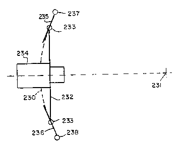
Figure 13 shows another rail system scanning apparatus
for moving an image receiver 234 relative to a scene. Dashed
curve 230 is the scanning arc about convergent point 231.
Heavy line 232 represents a mounting plate which moves along
arc 230 via bearings 233 and supports image receiver 234.
This assembly is driven by a motor (not shown) to provide
approximate sinusoidal motion. Travelling along a single arc
reduces the usefulness to a single convergent distance. The
rails 235 and 236 are designed tangent to the desired arc at
bearings 233. Furthermore, these rails can be pivoted about
shafts 237 and 238 by positioners, previously described for
convergent rail 13, to approximate a wide range of arcs which
center on convergent points at varying distances from the
image receiver. Thus, as long as the motion is small, the
image receiver 234 will travel in an approximate arc about
convergent point 231. This approximation is quite good since
the angles are small, about one milliradian.
Another rail system is illustrated in Figure 14. An
image receiver or camera 260 includes a lens 261 and an
optical path 62 which passes through the convergent point
263. The image receiver 260 moves on fixed rail 264 with
bearing 265 and moves on the rotatable rail 266 with bearing
267 and connecting linkage 268. A pair of parallel rails 264
may be provided for stability. The image receiver 260 is
moved along the rails and to producing scanning motion about
the convergent point 263 as approximated by rail 264. The
angle of the image receiver 260 is changed by the camera
pivoting about the bearing 265 as forced by the rail 266,
bearing 267, linkage 268 and the scanning motion. This is a
modification of the rail system of Figure 4 in that the pair
of parallel rails 64 in Figure 14 are not displaced along the
optical path as parallel rails 11 and 12 in Figures 1-4.
i
CA 02097319 2002-06-04
-21-
The approximation that the different positions along
the arch are equidistant from the convergent point 263 holds
for small changes in the angle in the optical axis 262 which
is preferable one milliradian. At one milliradian, the
distant between the image receiver 260 and the ideal
convergent point 263 changes 0.5 parts per million (ppm) and
the ideal convergent point moves 0.5 ppm. These errors are
much smaller than the best media resolution of 100 ppm and
much smaller than the resolution of television which is
approximately 5,000 ppm.
The angle of rail 266 may be adjusted to change the
position of the convergent point 263 and define a new
scanning path having views equally distant from the
convergent point as is rail 13.
Figure 15 shows scanning apparatus which performs
optical path manipulation for a fixed image receiver 240.
Optical path manipulation may be accomplished by reflection
or refraction. Image receiver 240 is aimed at convergent
point 241 via nominal optical path 242 obtained with the
mirrors 243 and 244 in positions B and B'. The scanning is
accomplished by rotating the mirrors cyclically between
extreme positions A, A', C and C'. The mirrors are rotated so
that the resulting optical paths always go through the
convergent point 241. Functionally, mirror 243 produces the
required scan while mirror 244 corrects for the resulting
optical path angle to maintain the length of the optical path
between the image receiver 240 and the convergent point 241
substantially fix and aim the optical path at the convergent
point 241.
Similarly, there are many different mechanical and
electronic solutions to the autostereoscopic scanning
problem. Although all the embodiments have been mechanical
and optical, the same effect and results can be achieved or
simulated by computer generated images simulating the
recorder systems described herein. Software programs capable
of such simulation which manipulate hierarchy and control
i i
CA 02097319 2002-06-04
-22-
camera movement include SCULPT IVD (trade mark) from Byte by
Byte and TURBOSILVER (trade mark) from Impulse.
The recorder as used herein is to mean that portion of a
recorder which includes its optics and the sensor at the
imaging plane. In a film camera, the imaging plane is at the
film. Thus the images are recorded at the imaging plane. For
electronic video cameras, a sensor, for example a CCD chip or
the equivalent, is at the imaging plane with the recording of
the image being remote. In this application, the optics and
the sensor are the portions being moved with the remote
recording being stationary as is the magazine in Figures 1-3.
Although the present invention has been described and
illustrated in detail, it is to be clearly understood that
the same is by way of illustration and example only, and is
not to be taken by way of limitation. The spirit and scope of
the present invention are to be limited only by the terms of
the appended claims.