Language selection

Search

Patent 2097401 Summary

Third-party information liability

Some of the information on this Web page has been provided by external sources. The Government of Canada is not responsible for the accuracy, reliability or currency of the information supplied by external sources. Users wishing to rely upon this information should consult directly with the source of the information. Content provided by external sources is not subject to official languages, privacy and accessibility requirements.

Claims and Abstract availability

Any discrepancies in the text and image of the Claims and Abstract are due to differing posting times. Text of the Claims and Abstract are posted:

  • At the time the application is open to public inspection;
  • At the time of issue of the patent (grant).
(12) Patent: (11) CA 2097401
(54) English Title: TRACKED VEHICLE
(54) French Title: VEHICULE CHENILLE
Status: Expired and beyond the Period of Reversal
Bibliographic Data
(51) International Patent Classification (IPC):
  • B62D 55/06 (2006.01)
  • B60S 09/10 (2006.01)
  • B66F 11/04 (2006.01)
  • E02F 09/02 (2006.01)
  • E02F 09/08 (2006.01)
  • E02F 09/14 (2006.01)
(72) Inventors :
  • MERRITT, JOHN T. (United States of America)
(73) Owners :
  • PATENTIALS INCORPORATED
(71) Applicants :
  • PATENTIALS INCORPORATED (United States of America)
(74) Agent: BERESKIN & PARR LLP/S.E.N.C.R.L.,S.R.L.
(74) Associate agent:
(45) Issued: 2000-09-05
(22) Filed Date: 1993-05-31
(41) Open to Public Inspection: 1993-12-06
Examination requested: 1995-06-01
Availability of licence: N/A
Dedicated to the Public: N/A
(25) Language of filing: English

Patent Cooperation Treaty (PCT): No

(30) Application Priority Data:
Application No. Country/Territory Date
07/894,107 (United States of America) 1992-06-05

Abstracts

English Abstract


A small, maneuverable, self-propelled tracked machine
with a bucket or a digging tool. The machine is small and light
enough to enter and be used in places, such as residential yards,
in which traditional machines with buckets and digging tools,
because of their size and weight, cannot be used. A three-stage
gear pump powers the tracks and the boom on the bucket or digger.
The machine has four outriggers to stabilize the machine during
use, the outxiggers arranged substantially perpendicular to each
other and at angles of approximately forty-five degrees from the
longitudinal axis of the machine.


Claims

Note: Claims are shown in the official language in which they were submitted.

Claims
1. A compact self-propelled machine having a
longitudinal axis, said machine comprising:
(a) a platform;
(b) a pair of spaced apart tracks operably attached to
the platform for propelling the platform;
(c) a plurality of spaced apart outriggers operatively
attached to the platform, and movable from a substantial vertical
rest position to a ground engaging position in which the
outrigger engages the ground beyond the platform to provide
greater stability to the machine than that afforded by said pair
of spaced tracks;
(d) an extendable boom attached to the platform and
allowing 360° of rotation with respect to the platform;
(e) a tool removably attached to the end of the boom;
and
(f) an engine mounted to the platform for powering the
spaced apart tracks, outriggers and boom.
2. The self-propelled machine of claim 1 wherein the
tracks are formed from a non-conductive elastomeric material.
3. The self-propelled machine of claim 1 wherein each
outrigger further includes a foot pivotally connected to the
ground engaging end of each outrigger.
4. The self-propelled machine of claim 1 wherein the
engine includes a three stage gear pump for providing hydraulic
power to the outriggers, boom and tools.
5. The self-propelled machine of claim 1 wherein the
platform has four corners and an outrigger extends angularly from
each corner, said outriggers being arranged substantially
perpendicular to each other and movable in a vertical planes
lying at angles of approximately 45° from the longitudinal axis
of the machine.
6. The self-propelled machine of claim 1 wherein the
tool comprises a bucket.

7. The vehicle of claims wherein the tool comprises a
digger.

Description

Note: Descriptions are shown in the official language in which they were submitted.


TRAC~CED ~TEHICLE
HACICGROUND OF THE INVENTION
Self-propelled vehicles with buckets arid digging tools
are well known. Such vehicles give the user the ability to
perform necessary tasks in a variety of locations.
The locations to which past vehicles could be taken and
in which they could be used were limited. The vehicles were too
large and heavy to be used in many locations in which their
abilities could have been used. A typical example of an
inaccessible location is a residential back yard. Traditional
vehicles of this type often cannot be driven in such areas, and
are often so heavy that they would severely harm the lawn. The
work which could have been performed using the vehicles had to be
completed in another way, e.g., by having persons trimming high
limbs of trees climb the trees individually, rather than being
lifted in a bucket.
SUMMARY OF THE INVENTION
This invention is a small, maneuverable. self-propelled
tracked machine with a bucket, digging tool or other implement or
implements. The tracks are rubber, ratherthan metal, providing
a measure of electrical insulation between the machine and the
ground on which it sits. A three-stage gear pump powers the
tracks and the boom on the bucket, digger or other implement.
The machine also has four outriggers to stabilize the machine.

The outriggers are arranged substantially perpendicular to each
other and at angles of approximately forty-five degrees from the
longitudinal axis of the machine.
BRIEF DESCRIPTION OF THE DRA47INOS
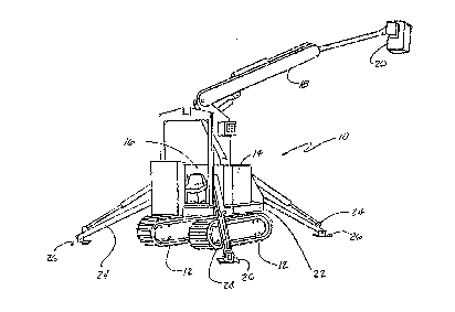
FIGURE 1 is a perspective view of the "tracked vehicle"
with boom extended and outriggers in place.
FIGURE 2 is a perspective view of the "traclced vehicle"
with boom contracted and outriggers in folded position.
DESCRIPTION OF THE PREFERRED EMBODIMENT
Although the present invention may use any of a variety
of tools, the embodiment: described herein is has a bucket in
which workers may be elevated. It will be understood that 'the
embodiment described herein is only one of many embodiments of
the invention. Tt is possible to make modifications without
departing from the scopes or spirit of the invention as claimed.
Referring now with particularity to the figures, it~can
be seen that a tracked lifting machine 10 is provided. The
machine 10 has two rubber tracks 1:. The 'tracks 12 are powered
by a three-stage gear pump 14. The engine used to power the gear
pump 14 can be of any type suitable to the application, e.g,, a
diesel engine.
The machine i,s equipped with a hydraulically operated
boom 18 which raises and positions the bucket 20. The boom 18
_2_

can be lifted through an angle from a plane parallel to the
ground, and can be extended to further lift the bucket 20 and
extend it away from the machine 10. Further, the boom 18 can
rotated about the point of attachment to the platform 22 through
a full 360°. The ability to pivot the boom 18 in this manner
allows the operator of the machine 10 to reach more positions
with the bucket 20 than with a traditional machine whose boom
cannot be rotated through 360°.
The abilities to rotate the boom 18 through 360° and to
extend the boom 18 so the bucket 20 reaches far from the
machine 10 are dependent upon the four outriggers 24, thea.r
placement and positioning on the machine 10. Because the
machine 10 is so small in length and width, giving it a small
base, to extend the boom 18 and bucket 20 fa.r without the
outriggers 24 would make the machine 10 and tend to tip it over.
The location of the outriggers 24 on the machine 10 is
important to the stability of the machine 10. An outrigger 24 is
placed approximately at each corner .of the machine. l0. Each
outrigger 24 extends in a direction which is at an angle of
approximately 45° to the longitudinal axis of the machine. when
the outrigger 24 is extended, the foot 26 of the outrigger 24 is
placed on the ground far outside of the base of the machine 10.
For example, the foot 26 of the front right outrigger 24 is both
far in front and far to the right of the base of the machine 10.
Together, the four outriggers 24 form a generally rectangular
-3-

~U~~~(~1
area much larger than the base of the machine 10. This provides
a much more stable base for the machine 10.
The embodiment of the invention disclosed herein is but
one embodiment of the invention, and modifications and variations
can be made without departing from the spirit or scope of the
invention as claimed.
-4-

Representative Drawing
A single figure which represents the drawing illustrating the invention.
Administrative Status

2024-08-01:As part of the Next Generation Patents (NGP) transition, the Canadian Patents Database (CPD) now contains a more detailed Event History, which replicates the Event Log of our new back-office solution.

Please note that "Inactive:" events refers to events no longer in use in our new back-office solution.

For a clearer understanding of the status of the application/patent presented on this page, the site Disclaimer , as well as the definitions for Patent , Event History , Maintenance Fee  and Payment History  should be consulted.

Event History

Description Date
Inactive: IPC from MCD 2006-03-11
Time Limit for Reversal Expired 2002-05-31
Letter Sent 2001-05-31
Grant by Issuance 2000-09-05
Inactive: Cover page published 2000-09-04
Inactive: Final fee received 2000-06-01
Pre-grant 2000-06-01
Inactive: Adhoc Request Documented 2000-05-12
Amendment Received - Voluntary Amendment 2000-04-20
Letter Sent 2000-01-12
Notice of Allowance is Issued 2000-01-12
Inactive: Status info is complete as of Log entry date 2000-01-10
Inactive: Application prosecuted on TS as of Log entry date 2000-01-10
Inactive: Approved for allowance (AFA) 1999-12-07
All Requirements for Examination Determined Compliant 1995-06-01
Request for Examination Requirements Determined Compliant 1995-06-01
Application Published (Open to Public Inspection) 1993-12-06

Abandonment History

There is no abandonment history.

Maintenance Fee

The last payment was received on 2000-05-30

Note : If the full payment has not been received on or before the date indicated, a further fee may be required which may be one of the following

  • the reinstatement fee;
  • the late payment fee; or
  • additional fee to reverse deemed expiry.

Patent fees are adjusted on the 1st of January every year. The amounts above are the current amounts if received by December 31 of the current year.
Please refer to the CIPO Patent Fees web page to see all current fee amounts.

Fee History

Fee Type Anniversary Year Due Date Paid Date
Registration of a document 1998-02-04
MF (application, 5th anniv.) - small 05 1998-06-01 1998-05-26
MF (application, 6th anniv.) - small 06 1999-05-31 1999-05-31
MF (application, 7th anniv.) - small 07 2000-05-31 2000-05-30
Final fee - small 2000-06-01
Owners on Record

Note: Records showing the ownership history in alphabetical order.

Current Owners on Record
PATENTIALS INCORPORATED
Past Owners on Record
JOHN T. MERRITT
Past Owners that do not appear in the "Owners on Record" listing will appear in other documentation within the application.
Documents

To view selected files, please enter reCAPTCHA code :


To view images, click a link in the Document Description column (Temporarily unavailable). To download the documents, select one or more checkboxes in the first column and then click the "Download Selected in PDF format (Zip Archive)" or the "Download Selected as Single PDF" button.

List of published and non-published patent-specific documents on the CPD .

If you have any difficulty accessing content, you can call the Client Service Centre at 1-866-997-1936 or send them an e-mail at CIPO Client Service Centre.

({010=All Documents, 020=As Filed, 030=As Open to Public Inspection, 040=At Issuance, 050=Examination, 060=Incoming Correspondence, 070=Miscellaneous, 080=Outgoing Correspondence, 090=Payment})


Document
Description 
Date
(yyyy-mm-dd) 
Number of pages   Size of Image (KB) 
Abstract 1994-02-18 1 27
Description 1994-02-18 4 134
Claims 1994-02-18 1 21
Drawings 1994-02-18 1 32
Claims 1999-12-02 2 50
Representative drawing 1999-04-05 1 15
Representative drawing 2000-08-27 1 12
Courtesy - Certificate of registration (related document(s)) 1998-05-26 1 116
Commissioner's Notice - Application Found Allowable 2000-01-11 1 166
Maintenance Fee Notice 2001-06-27 1 178
Fees 2000-05-29 1 33
Correspondence 2000-05-31 1 33
Fees 1998-05-25 1 56
Fees 1999-05-30 1 47
Fees 1997-05-07 1 66
Fees 1996-05-30 1 57
Fees 1995-05-30 1 58
Prosecution correspondence 1995-05-31 1 46
Courtesy - Office Letter 1995-07-25 1 32
Prosecution correspondence 1998-08-12 3 101
Examiner Requisition 1998-02-12 2 51