Note: Descriptions are shown in the official language in which they were submitted.
~u~~~~~
DIFFUSER FOR HAIR DRYER
BACKGROUND OF THE INVENTION
Technical Field
The invention relates generally to hair dryers and, more
particularly, to diffusers for reducing the velocity of the
airflow discharged from a hair dryer.
Related Prior Art
It is generally known to provide a hair dryer having a
nozzle with a diffuser or similar attachment for spreading or
enlarging the airstream produced by the hair dryer and discharged
through the nozzle. It is also known to provide such diffusers
to reduce the velocity of the airstream. U. S. Patent
No. 4,230,279, which issued to Forsberg on October 28, 1980,
discloses one such diffuser.
It is also generally known to provide a hair dryer with an
adjustable damper far controlling the velocity of the discharged
airstream. U.S. Patent No. 4,097,722, which issued to Soler, et
al. on June 27, 1978, illustrates an example of such an
adjustable hair dryer discharge control mechanism.
Attention is also directed to the following United States
patents:
1,758,339 Wager May 13, 1930
2,443,071 Honexkamp, et al, June 8, 1948
3,943,329 Hlavac March 9, 1978
AND19120.APP
~~~1~~.~
SUMMARY OF THE INVENTION
According to one aspect, the invention comprises a diffuser
for a hair dryer having an air discharge nozzle, the diffuser
comprising a body having a side wall defining a first opening
adapted to communicate with the nozzle and a second opening, the
body defining an air passage communicable between the first and
second openings for conducting therebetween an air flow, a grill
overlying the second opening and defining a plurality of
discharge openings, a plurality of generally hollow fingers
extending from the grill outwardly of the air passage, the
fingers defining respective finger discharge openings and
respective finger discharge passage portions communicable between
the air passage and the finger discharge openings, and valve
means for selectively and adjustably controlling the flow of air
from the air passage through the discharge openings and the
finger discharge openings.
According to another aspect, the invention comprises a
diffuser for a hair dryer having an air discharge nozzle, the
diffuser comprising a body adapted to be supported on the
discharge nozzle and having a side wall defining an opening and a
first exterior surface adjacent the opening, a grill fixed to the
body and extending across the opening, a valve member located
between the body and the grill and providing a second exterior
surface flush to and adjacent the first exterior surface that can
be gripped by a user of the hair dryer, and means for supporting
the valve member to afford selective relative movement by the
ANDIA128.APP ~ 2 ~
user of the second exterior surface relative to the first
exterior surface.
According to another aspect, the invention comprises a
diffuser for a hair dryer having an air discharge nozzle, the
diffuser comprising a body having an open end and an air passage
communicable with the nozzle for conducting an air flow to the
open end, a grill overlying the open end and including a
plurality of spokes defining therebetween a plurality of air
discharge openings, a plurality of generally hollow fingers on
the grill and extending outwardly of the air passage, each finger
having a finger discharge opening and a discharge passage portion
communicable between the air passage and the finger discharge
opening for conducting a portion of the air flow and, valve means
located between the body and the grill for selectively and
adjustably controlling the air flow through the fingers.
DESCRIPTION OF THE DRAWINGS
Figure 1 is a side view of a hair dryer and a diffuser
embodying the invention.
Figure 2 is an enlarged, front view of the diffuser shown in
Fig. 1.
Figure 3 is a side elevation view of the diffuser shown in
Fig. 2.
Figure 4 is a cross-sectional view taken along line 4=4 in
Fig. 2.
AND19129.APP - 3 -
Figure 5 is a front elevational view, partially broken away
for illustration, of the diffuser illustrated by Fig. 2 shown in
a second position.
Figure 6 is a cross-sectional view taken along line 6-6 in
Fig. 5.
Figure 7 is a cross-sectional view taken along line 7-7 in
Fig. 5.
Figure 8 is an enlarged view of a portion of the diffuser
shown in Fig. 6.
Figure 9 is an enlarged view of a portion of the diffuser
shown in Fig. 6.
Figure 10 is a front elevational view of a valve member
included in the diffuser shown in Fig. 1.
Figure 11 is a view taken along line 11-11 in Fig. 9.
DETATLED DESCRIPTION OF THE PREFERRED EMBODIMENT
The drawings illustrate a diffuser 10 for use on a
conventional hair dryer 14 including a discharge nozzle 18 (shown
in phantom in Fig. 3). The hair dryer 14 is operable to produce
an airflow discharged through the nozzle 18.
The diffuser 10 is mounted on the. discharge nozzle 18 to
reduce the velocity of the airflow by enlarging the cross-
sectional area of the airflow from the hair dryer 14. The
diffuser 10 is preferably fabricated of heat-resistant plastic or
a similar material and includes a bell-shaped housing or body 22.
The body 22 includes (Fig. 6) an imperforate side wall 26
AND18128.APP - 4 -
~ii~i ~'' ~J
extending circumferentially about an axis and having an inner
surface and an outer surface. The side wall 26 defines a first,
generally circular and small opening 30 at one end of the body
22. For reasons discussed below, the side wall 26 also defines
an inwardly turned step or shoulder 34 located adjacent the first
opening 30.
The side wall 26 also defines a second, larger generally
circular exhaust opening 38 at the other end of the body 22. For
reasons discussed below, the side wall 26 provides (Figs. 3 and
9) a first exterior surface 42 extending about the periphery of
the exhaust opening 38. The side wall 26 also provides (Fig. 6)
a stepped end 46 adjacent the exhaust opening 38. The diffuser
body 22 and side wall 26 also define an air passage 50
communicable between the first and second openings 30, 38 for
conducting therebetween the airflow from the nozzle 18.
The diffuser 10 is adapted to be mounted on the nozzle 18 by
(Fig. 6) an extension joint 54 fixed to the diffuser body 22 and
removably attached to the nozzle 18 in a conventional manner.
More particularly, the extension joint 54 has a generally
cylindrical wall 58 that is telescopically received by the first
opening 30 in the body 22. A plurality of resiliently
deflectable clips 62 are circumferentially distributed around the
cylindrical wall 58 and have radially outwardly splayed ends.
The clips 62 engage the shoulder 34 adjacent the first opening 30
and lock the extension joint 54 to the diffuser body 22. A
plurality of tabs 66 (shown in Figs 3 and 6) are located on the
AND19128.APP - 5 -
N
BUJ I'.'~~~~
cylindrical wall 58 outside the body 22. The tabs 66 extend
into, and are engaged by, the discharge nozzle 18 in a
conventional manner so that the diffuser 10 is removably
supported by the nozzle 18.
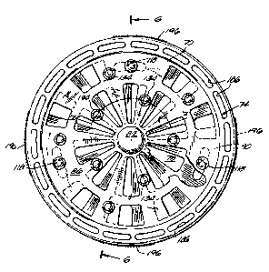
The diffuser 10 also includes (Figs. 2, 5 and 6) a grill 70
that is fixed to the body 22 in a position overlying the exhaust
opening 38. The grill 70 divides the exhaust opening 38 into an
annular, radially outer discharge area 74 and a generally
circular, radially inner valued discharge area 78. While variaus
constructions for the grill 70 can be used, the illustrated grill
70 includes (Fig. 2) a centrally located, imperforate hub cap 82
and a pair of generally annular inner and outer rings 86, 90 that
are concentrically arranged about the hub cap 82. A cylindrical
shank 94 (Figs. 6 and 8) extends from the hub cap 82 axially
inwardly of the diffuser body 22. The outer surface of the shank
94 is stepped so that the distal or axially inner end 98 of the
shank 94 has a circumference that is smaller than that of the
portion of the shank 94 adjacent the hub cap 82.
As shown in Fig. 6, the circumference of the grill 70 is
smaller than that of the exhaust opening 38. As a result, the
grill 70 and the portion of the side wall 26 adjacent the exhaust
opening 38 define therebetween the radially outer discharge area
74.
The grill 70 also includes (Fig. 2) a series of
circumferentially spaced spokes 110 that extend radially from the
hub cap 82 past the inner ring 86 to the outer ring 90.
AND18129.APP - 6 -
CA 02097985 2003-08-O1
67363-1014
Preferably, the spokes 110 increase in circumferential width with
increasing radial distance from the hub cap 82. In the
embodiment of the diffuser 10 shown in the drawings, the spokes
110 are equi-angularly spaced about the hub cap 82. As a result
of the spacing of the spokes 110, the spokes 110 subdivide the
radially inner valued discharge area 78 into (Figs. 2 and 4) a
plurality of radially inner discharge openings 1I2. As best
shown in Fig. 2, the grill 70 also includes a series of
imperforate regions 114 that are circumferentially spaced-apart,
that are located radially outside the inner ring 86, and that
extend between adjacent spokes 110,
The grill 70 is fixed to the body 22 by a plurality of
fasteners 118. As best shown in Figs. 5 and 6, the fasteners 118
extend through circumferentially spaced fastener holes (not
shown) located in the imperforate regions of the grill 70. The
fastener holes are aligned with (Fig. 6) an equal number of
fastener bosses 126 which extend from the inner surface of the
diffuser body 22 and with which the fasteners 118 can be engaged.
In the illustrated embodiment, three screws serve as fasteners
118 to fix the grill 70 to the body 22. Preferably, the diffuser
also includes a plurality of screw caps 130 (only one shown in
Fig. 6) for covering the heads of the screws.
The diffuser 10 also includes a plurality of generally
hollow fingers 134 extending from the spokes 110 outwardly of the
air passage 50. In the illustrated embodiment of the diffuser
10, the grill 70 includes (Figs. 2 and 5) five fingers 134 that
_7_
are located on alternating spokes 110 and that are located
radially inwardly of the inner ring 86. The illustrated grill 70
also includes five fingers 134 that are located on alternating
spokes 110 radially outwardly of the inner ring 86.
As best shown in Figs. 4 and 7, the fingers 134 are
generally hollow cylinders having a first end 138 defining a
finger passage opening or inlet 140 in the associated spoke 110.
Each finger 134 also has a distal, second end 142 extending
generally away from the body 22. The distal end 142 of each
finger 134 is closed. However, spaced slightly axially inwardly
of the end of each finger 134 is a circumferentially extending
finger discharge opening 146. A finger passage portion 150
communicates between the finger passage inlet 140 and the finger
discharge openings 146. As discussed below, under some
conditions, the finger passage portion 150 conducts a portion of
the airflow from the air passage 50 in the diffuser body 22 from
the finger inlet 140 to the finger discharge openings 146.
The diffuser 10 also includes (Fig. 6) valve means 154 for
selectively and adjustably controlling the flow of air from the
air passage 50 through the radially inward discharge area 78. In
particular, the valve means 154 affords the user of the hair
dryer 14 selective and adjustable control of the airflow through
the radially inward discharge area 78. The valve means 154 can
be operated so that airflow can be alternately directed to the
finger discharge openings 146 and the radially inward discharge
openings 112 in the grill 70. While various suitable
AND1912B,APP - 8 -
i
CA 02097985 2003-08-O1
67363-1014
constructions for such the valve means 154 can be used, in
the illustrated embodiment, the valve means 154 includes a
valve member 158 that is located between the diffuser
body 22 and the grill 70.
As best shown in Figs. 8-11, the valve member 158 includes a
centrally located hub 160, inner and outer rings 162, 166
concentrically surrounding the hub 160, and a dish-shaped
perforated wall 170 extending between the hub 160 and the inner
and outer rings 162, 166. As best illustrated by Figs. 8 and 11,
the hub 160 includes an axially extending cup portion 171 defined
by a cylindrical wall having an axially inner end and a radially
inwardly turned lip adjacent the inner end. The hub 160 is sized
(Figs. 6 and 8) to receive and house the shank 94 extending from
the hub cap 82. For reasons discussed below, the engagement
between the hub 160 and the hub cap 82 affords relative rotation
therebetween.
The perforated wall 170 includes (Fig. 10) a plurality of
louvers 174 extending radially from the hub 160 to the outer
ring. The louvers 174 are circumferentially spaced-apart and
increase circumferential width with radial distance from the hub
160 in a manner similar to the spokes 110 of the grill 70.
Accordingly, the louvers 174 also define radially inward valve
openings 178 that are sized and shaped to correspond to the
radially inward discharge openings 112 provided by the grill 70.
The valve member 158 also includes a series of imperforate
regions 180 that extend between adjacent louvers 174 and between
_g_
~l~;~Y(v~ 7
the inner and outer rings 162, 166. The imperforate regions 180
define therein a plurality of circumferentially extending slots
182. When the valve member 158 is assembled with the grill 70
and body 22, the slots 182 (Fig. 5) surround the fasteners 118.
Each of the slots 182 has an arc length affording movement of the
valve member 158 relative to the fasteners 118 and, therefore,
relative to the grill 70 and diffuser body 22 in a manner
discussed below. The arc length of the slots 182 is also
specific, however, to limit the range of rotation of the valve
member 158 relative to the body 22 and the grill 70.
The outer ring 166 of the valve member 158 also provides
(Fig. 10) a plurality of circumferentially spaced, radially
outward discharge openings 186. The radially outward discharge
openings 186 overlie the radially outward discharge area 74
defined by the periphery of the grill 70 and the diffuser body 22
and, therefore, are always open.
As best shown in Figs. 9 and 11, the outer ring 166 also
provides an axially outwardly facing annular groove 188. The
groove 188 has a width sufficient to slidingly receive the flange
102 on the outer ring 90 of the grill 70. The outer ring 166 of
the valve member 158 also includes a rim 190 providing a second
exterior surface 194 that extends about the periphery of the
exhaust opening 38. As shown in Fig. 2, the second exterior
surface 194 is substantially flush to and adjacent the first
exterior surface 42. For reasons discussed below, the second
exterior surface 194 has (Figs. 2 and 3) several
AND19128.APP ~ 1 O ~
~v~i~~~
circumferentially extending regions 196 of radially extending,
raised ribs that facilitate the gripping of the valve member 158
by a user of the hair dryer. Preferably, the first exterior
surface 42 on the body 22 is relatively smooth so that the ribbed
regions 196 of the valve member 158 are raised from the first
outer surface 42 on the body 22.
As best shown in Fig. 9, the rim 190 of the valve member 158
also provides a stepped, axial inner end 198 that is configured
to nest with the stepped end 46 of the side wall 26 and to be
slidable relative thereto.
The valve means 154 also includes (Fig. 6) means 202 for
supporting the valve member 158 for selective movement by the
user of the hair dryer 14 relative to the diffuser body 22 and
grill 70. While various suitable means can be used for
supporting the valve member 158, in the illustrated embodiment
such support means 202 includes the rotatable engagement between
the hub 160 and the hub cap 82, the slidable engagement of the
flange on the grill 70 and the groove 188 in the valve member
158, and the nested, slidable engagement of the stepped rim 190
of the valve member 158 with the stepped end 46 of the side wall
26. These points of slidable contact afford the nested assembly
of the diffuser body 22, valve member 158, and grill 70 and
permit sliding rotation of the valve member 158 relative to the
body 22 and grill 70. In addition, the nested assembly of the
body 22, grill 70 and valve member 158 provides a diffuser
construction having a pair of elements, i.e. the body 22 and
AND19128,APP - 1 1 -
CA 02097985 2003-08-O1
67363-1014
valve member 158, that provide respective exposed exterior
surfaces 42, 194. Because the exterior surfaces 42, 194 are
exposed when the diffusser is assembled, the user of the diffuser
can easily grasp those surfaces and need not reach into the
discharged airflow to do so.
The means 202 for supporting the valve member 158 and for
affording rotation of valve member 158 relative to the grill 70
and diffuser body 22 also include the slots 182 surrounding the
fasteners 118. The slots 182 are arcuate to afford by the user
of the diffuser 10 to move or rotate the valve member 158
relative to the fasteners 118 and, therefore, relative to the
grill 70 and diffuser body 22.
In particular, the valve member 158 is rotatable between a
first, opened position (not shown) and a second, closed position
shown in Figs. 2 and 4. Fig. 5 illustrates the valve
member 158 in an intermediate position between the opened and
closed positions. When in the closed position (Figs. 2 and 4),
the louvers 174 overlie the radially inward discharge openings
112 in the grill 70. Also, when the valve member 158 is in the
closed position, the radially inner valve openings 178 overlie
the finger inlets 140 and permit portions of the airflow in the
diffuser passage to pass into the finger discharge passage
portions 150 and out the finger discharge openings 146.
As noted above, the radially outer discharge openings 186 in
the valve member 158 are not valued, i.e., they are always open,
and therefore also permit passage of a portion of the airflow
-12-
from the diffuser air passage 50 to exit the diffuser 10 when the
valve member 158 is in the closed position.
When the valve member 158 is moved toward the open position
(Figs. 5 and 6), the valve openings 178 overlie, to an increasing
extent, the radially inward discharge openings 112 in the grill
70 and permit a portion of the airflow to pass therethrough from
the diffuser air passage 50. Also, when the valve member 158 is
moved toward the opened position, the louvers 174 overlie, to an
increasing extent, the finger inlets 140 thereby decreasing the
amount of airflow that enters the finger passage portions 150.
As a result of the increasing opening of the radially inner
discharge openings 112 and the decreasing opening of the finger
inlets 140 as the valve member 158 moves toward the opened
position, rotation of the valve member 158 between the opened and
closed positions controls the amount of airflow respectively
passing through the radially inward discharge openings 112 and
the finger passage portions 150 in an inverse propartion.
As mentioned above, the slots 182 in the valve member 158
limit the range of rotation of the valve member between the open
and closed positions so that, for example, the valve member 158
cannot be rotated beyond the closed position (clockwise in
Fig.. 2) to permit air flow through the valve openings 178 and
discharge openings 112.
Because the second external surface 194 of the valve member
158 is exposed and easily graspable when the diffuser 10 is
assembled, and due to the construction affording movement of the
AN01912A.APP - 1 3 -.
~~i~'1~~
valve member 158 relative to the grill 70 and diffuser body 22,
the diffuser 10 thus provides means for affording selective
movement by a user of the diffuser 10 of the second external
surface 194 relative to the first external surface of the
diffuser body 22. Such an arrangement affords adjustment by the
user of the diffuser discharge without having to reach into the
discharged air flow.
Various additional features of the invention are set forth
in the following claims.
AND18t28.APP -~, L~-