Some of the information on this Web page has been provided by external sources. The Government of Canada is not responsible for the accuracy, reliability or currency of the information supplied by external sources. Users wishing to rely upon this information should consult directly with the source of the information. Content provided by external sources is not subject to official languages, privacy and accessibility requirements.
Any discrepancies in the text and image of the Claims and Abstract are due to differing posting times. Text of the Claims and Abstract are posted:
| (12) Patent: | (11) CA 2098458 |
|---|---|
| (54) English Title: | FASTENING SYSTEM FOR A CIRCULAR SAW BLADE |
| (54) French Title: | SYSTEME DE FIXATION DE LA LAME POUR UNE SCIE CIRCULAIRE |
| Status: | Expired and beyond the Period of Reversal |
| (51) International Patent Classification (IPC): |
|
|---|---|
| (72) Inventors : |
|
| (73) Owners : |
|
| (71) Applicants : |
|
| (74) Agent: | OYEN WIGGS GREEN & MUTALA LLP |
| (74) Associate agent: | |
| (45) Issued: | 1997-04-08 |
| (22) Filed Date: | 1993-06-15 |
| (41) Open to Public Inspection: | 1994-01-04 |
| Examination requested: | 1994-12-02 |
| Availability of licence: | Yes |
| Dedicated to the Public: | N/A |
| (25) Language of filing: | English |
| Patent Cooperation Treaty (PCT): | No |
|---|
| (30) Application Priority Data: | ||||||
|---|---|---|---|---|---|---|
|
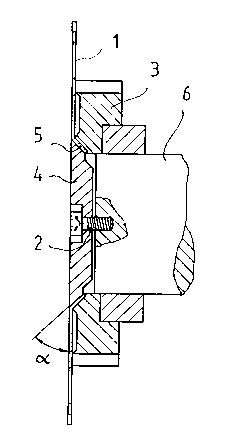
A fastening system for a circular saw blade (1, 10), wherein
the circular saw blade is fastened by means of a screw/screws
(2, 9) to a fastening flange on the turning arbor (6), to a
chipping edger (3) in a hewing saw, or to a chipping cutter
(8). The fastening part (5, 11) of the circular saw blade (1,
10) is made conical and the circular saw blade (1, 10) is fas-
tened between two corresponding conical surfaces.
Note: Claims are shown in the official language in which they were submitted.
Note: Descriptions are shown in the official language in which they were submitted.
2024-08-01:As part of the Next Generation Patents (NGP) transition, the Canadian Patents Database (CPD) now contains a more detailed Event History, which replicates the Event Log of our new back-office solution.
Please note that "Inactive:" events refers to events no longer in use in our new back-office solution.
For a clearer understanding of the status of the application/patent presented on this page, the site Disclaimer , as well as the definitions for Patent , Event History , Maintenance Fee and Payment History should be consulted.
| Description | Date |
|---|---|
| Time Limit for Reversal Expired | 2010-06-15 |
| Letter Sent | 2009-06-15 |
| Inactive: Office letter | 2007-02-20 |
| Inactive: Entity size changed | 2007-01-26 |
| Inactive: Corrective payment - s.78.6 Act | 2007-01-17 |
| Inactive: IPC from MCD | 2006-03-11 |
| Inactive: IPC from MCD | 2006-03-11 |
| Inactive: IPC from MCD | 2006-03-11 |
| Grant by Issuance | 1997-04-08 |
| Request for Examination Requirements Determined Compliant | 1994-12-02 |
| All Requirements for Examination Determined Compliant | 1994-12-02 |
| Application Published (Open to Public Inspection) | 1994-01-04 |
There is no abandonment history.
| Fee Type | Anniversary Year | Due Date | Paid Date |
|---|---|---|---|
| MF (patent, 4th anniv.) - small | 1997-06-16 | 1997-06-09 | |
| MF (patent, 5th anniv.) - small | 1998-06-15 | 1998-06-01 | |
| MF (patent, 6th anniv.) - standard | 1999-06-15 | 1999-05-25 | |
| MF (patent, 7th anniv.) - standard | 2000-06-15 | 2000-05-24 | |
| MF (patent, 8th anniv.) - standard | 2001-06-15 | 2001-05-28 | |
| MF (patent, 9th anniv.) - standard | 2002-06-17 | 2002-05-27 | |
| MF (patent, 10th anniv.) - standard | 2003-06-16 | 2003-05-22 | |
| MF (patent, 11th anniv.) - standard | 2004-06-15 | 2004-05-25 | |
| MF (patent, 12th anniv.) - standard | 2005-06-15 | 2005-05-16 | |
| MF (patent, 13th anniv.) - standard | 2006-06-15 | 2006-06-05 | |
| 2007-01-17 | |||
| MF (patent, 14th anniv.) - standard | 2007-06-15 | 2007-06-04 | |
| MF (patent, 15th anniv.) - standard | 2008-06-16 | 2008-06-10 |
Note: Records showing the ownership history in alphabetical order.
| Current Owners on Record |
|---|
| KAUKO RAUTIO |
| Past Owners on Record |
|---|
| None |

