Note: Descriptions are shown in the official language in which they were submitted.
-- 20 3916 3
1 As a patient's body temperature i8 critical with
2 respect to sust~ining life, thermal blankets are often used
3 to provide warmth or cooling directly to patients as
4 needed. For instance, many post-surgery procedures include
the use of a thermal blanket wherein warm air is
6 distributed over the patient's body for body temperature
7 control purposes for reducing the effects of shock and
8 trauma. As such blankets may become soiled, thermal
9 blankets are preferably of the disposable type, the blanket
being formed by thermoplastic sheets heat sealable at their
11 peripheries to define an envelope for receiving pressurized
12 air and orifices defined in the lowermost blanket sheet
13 permits the warm air to be directed toward the patient's
14 body.
The invention relates to patient warming or cooling
16 blankets employing pressurized temperature controlled air
17 wherein a substantially uniform temperature of air may be
18 directly imposed over the entire area of a supine patient.
19 Thermal blankets for controlling medical patients'
body temperatures are shown in patents whereby the blankets
21 use elongated passages or cells for distributing the
22 thermal medium over the area of the blanket. Manifolds
23 may be used, or a plurality of longitudinally extending
24 passages may be employed. Such devices are expensive to
manufacture and are not suitable for disposable
26 applications. Further, difficulty is experienced in
27 providing substantially uniform temperatures throughout the
28 area of the blanket.
29 Temperature controlled pads or blankets utilizing
complex medium circulating paths are known, but again, such
- 209916~
1 devices are complicated and expensive and not suitable for
2 disposable body temperature regulating blankets.
3 In a blanket warmer of an envelope type, a plurality
4 of air orifices are defined. The spacing of the orifices
varies over the area of the blanket in order to provide a
6 more uniform air distribution, i.e. the areas subject to
7 the greatest positive pressure have the fewer orifices, but
8 such an arrangement does not effectively control the
9 distribution of the temperature of the air, and has the
undesirable effect of subjecting portions of the patient's
11 body to greater air velocities and quantities than other
12 portions of the body.
13 In a patient warming or cooling blanket wherein
14 pressurized temperature controlled air is injected into a
heat sealed envelope and orifices located in the bottom
16 sheet of the envelope permit the air to impinge upon the
17 patient's body. The envelope sheets are staked or tacked
18 at evenly spaced locations to control inflation and provide
19 a dissemination and distribution of the air entering the
foot region of the blanket wherein the tacks partially
21 define interconnected cells receiving the treated air.
22 This type of blanket may be economically manufactured for
23 producing a disposable single-use product. However, as the
24 temperature controlled air enters the foot end of the
blanket, sufficient heat loss has occurred as the air
26 travels toward the head region of the blanket to prevent
27 a uniform temperature air to be distributed throughout the
28 blanket area.
29 It is a prime object of the present invention to
provide a patient temperature control blanket utilizing
31 pressurized air wherein an improved air path is produced
-- 2Q99163
1 within the blanket configuration by economical means to
2 minimize heat loss as the air is distributed throughout
3 the blanket resulting in a substantially uniform air
4 temperature distribution over the blanket area.
Another object of the invention is to provide a
6 temperature control blanket for distributing thermally
7 regulated pressurized air over the body of a patient
8 wherein the temperature of the distributed air is
9 substantially uniform, and the manufacturing techniques
used are of such an economical nature as to permit the
11 blanket to be economically produced for disposable single-
12 use applications.
13 A further object of the invention is to provide a
14 temperature control blanket for medical use formed of
thermoplastic sheets heat sealed at their peripheries and
16 staked, welded or tacked by heat sealing procedures
17 intermediate the blanket periphery to control inflation
18 and provide air flow passages and paths which reduce
19 temperature differentiation throughout the blanket area
and permit a substantially uniform temperature of air to
21 be distributed over the patient.
22 Yet another object of the invention is to provide
23 a pneumatic temperature control blanket which produces an
24 even, low pressure distribution of temperature controlled
air over the covered area regardless of where the blanket
26 air chamber may be compressed by superimposed blankets or
27 the like.
28 In the practice of the invention a disposable
29 pneumatic temperature control blanket is formed by sealing
thermoplastic sheets about their peripheries to define a
31 closed envelope. Preferably, at least one of the sheet's
2099163
1 exterior surfaces includes a layer of friction material to
2 aid in the retention of the blanket upon the patient's
3 body. An external air supply unit provides a low pressure
4 heated or dehumidified and cooled air through a flexible
hose, and the conditioned air is introduced into the
6 blanket chamber through a blanket mounted fitting.
7 The sheets defining the blanket envelope are staked
8 or tacked by a heat weld at spaced locations between the
9 sheets' peripheries, and such tacking provides a diffused
air flow passage throughout the envelope and aids in
11 preventing the envelope from being compressed at localized
12 regions such as to interfere with the flow of air
13 therethrough.
14 The location and spacing of predetermined tacks is
such that a low flow restrictive air passage is defined
16 within the blanket envelope in communication with the air
17 supply connection fitting whereby air introduced into the
18 envelope readily flows through the blanket throughout its
19 length to permit rapid dissemination of the air throughout
the entire blanket area. Preferably, the air supply is
21 connected to the blanket adjacent the blanket rear end, and
22 the air flows through the air passage toward the blanket
23 head end through the air passage.
24 The air passage within the blanket envelope may be
formed by spaced individual tacks, or an interrupted seam.
26 By using spaced tacks, even though the tacks are relatively
27 close to each other, the air may escape laterally from the
28 air passage into the lateral blanket portions throughout
29 the length of the air passage. Further, adjacent the
blanket head end auxiliary lateral air passages are defined
31 by the spacing of tacks to permit low restrictive air flow
2û99163
1 into lateral regions of the blanket adjacent the head and
2 shoulder region of the blanket as disposed over a patient.
3 By the use of the internal air passages, air flow
4 characteristics within the blanket envelope are improved
over prior art arrangements, and a substantially uniform
6 temperature of air can be distributed and discharged over
7 the blanket area and over the patient's body. Yet, the use
8 of the thermally sealed tacks permits the blanket to be
9 economically manufactured and feasibly producible for
disposable single-use applications.
11 The aforementioned objects and advantages of the
12 invention will be appreciated from the following
13 description and accompanying drawings wherein:
14 FIG. 1 iS a plan view of a temperature control
blanket utilizing the concepts of the invention, an
16 alternative air passage seam construction being illustrated
17 in dotted lines,
18 FIG. 2 is an elevational, enlarged, sectional view
19 of the inflated blanket as taken along Section 2 - 2 of
FIG. 1, and
21 FIG. 3 is a plan sectional view through the inflated
22 blanket as taken along Section 3 - 3 of FIG. 2, the air
23 flow through the passages being represented by arrows.
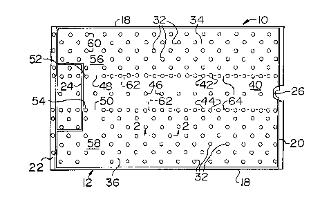
24 The pneumatic temperature control blanket 10 in
accord with the invention is preferably of a rectangular
26 configuration as will be appreciated from FIGS. 1 and 3.
27 Basically, the blanket consists of an envelope 12 defined
28 by a pair of polyethylene thermoplastic sheets 14 and 16,
29 the sheet 14 constituting a top sheet, while the sheet 16
forms the blanket bottom sheet. The sheets 14 and 16 are
2099163
1 heat æealed along their lateral edges 18, and along their
2 foot edges 20 and head end edges 22.
3 The head edges 22 are heat sealed at 24 to define
4 a non-inflatable region adjacent the neck, and at the foot
edges 20 a fitting 26 is affixed to the blanket envelope
6 for receiving an air supply hose, not shown, for providing
7 pressurized temperature controlled air to the blanket. A
8 non-woven wood pulp airlaid layer 28 is bonded to the
9 outside of the lower sheet 16 forming the lower surface of
the blanket 10, and the layer 28 forms a high friction
11 surface which retains the blanket upon the wearer.
12 A plurality of air orifices 30 extend through the
13 sheet 16 and the layer 28 whereby air within the envelope
14 12 passes through the orifices 30 onto the patient's body
located below the blanket.
16 The envelope sheets 14 and 16 are staked or tacked
17 together by a plurality of heat sealed tacks 32 which
18 interconnect the associated sheets and control the
19 expansion of the envelope 12 during inflation with
pressurized air. At the blanket lateral regions 34 and 36,
21 the tacks 32 are uniformly spaced from each other, and as
22 will be appreciated from FIG. 2, upon inflation of the
23 envelope 12 the air chambers 38 defined by adjacent tacks
24 32 are in communication with each other and air freely
flows between the chambers 38 for flow through the orifices
26 30. In order to reduce the resistance of the air flow
27 into the envelope 12 an elongated air passage 40 is defined
28 by tacks 42 and 44. The tacks 42 define a linear row
29 extending from the foot edges 20 toward the head edge 22,
and the spacing between adjacent tacks 42 is relatively
31 close, as will be appreciated from FIGS. 1 and 3, and is
-- ~Q99163
1 closer than the spacing between the tacks 32 defined in the
2 blanket lateral edges. Likewise, the tacks 44 are located
3 within a linear row identical to tacks 42 exten~ing from
4 the foot edge of the blanket toward the head edge. The
close proximity of the tacks 42 and 44 to each other,
6 respectively, defines the air passage 40 and permits
7 lateral dissemination of air within the passage 40 to the
8 lateral regions 34 and 36 as shown by the arrows, FIG. 3.
9 However, due to the proximity of the tacks 42 and 44 to
each other, respectively, lateral flow of the air from the
11 passage 40 is limited.
12Center tacks 46 are located within the air passage
13 40 in a linear configuration defining a longitudinal axis
14 of the air passage 40, and the center tacks 46 prevent
excessive separation of the sheets 14 and 16 within the
16 passage 40, without significantly restricting the passage
17 of air therethrough.
18As will be readily appreciated from FIGS. 1 and 3,
19 the air supply fitting 26 communicates with the foot end
of the air passage 40.
21At its head end the air passage 40 is provided with
22ports 48 and 50 defined within the air passage 40 adjacent
23 the envelope head end and head heat seal 24. The ports 48
24 and 50 are defined by a significant separation between the
last of the tacks 42 and 44 in their respective rows, and
26 the tacks 52 and 54.
27Lateral air passages 56 and 58 formed by a
28 significant spacing between tacks 32 and tacks 60
29 communicate with the ports 48 and 50, respectively. In
this manner the air flowing through air passage 40
31 encounters heat seal 24 and laterally passes through ports
2099163
1 48 and 50 into passages 56 and 58 whereby the air passing
2 through the ports is effectively distributed in the lateral
3 regions 34 and 36 of the blanket which are adjacent the
4 shoulder and chest blanket regions. Also, air flowing
through the passages 56 and 58 will flow through the
6 chambers 38 defined by the tacks 32 in the blanket lateral
7 regions and distribute air through the lateral regions.
8 The inflation of the blanket 10, and the air flow
9 through the passage 40, will cause the temperature
controlled air, usually heated, to flow laterally between
11 the tacks 42 and 44, and also through the ports 48 and 50,
12 and through the lateral passages 56 and 58 as shown by the
13 arrows, FIG. 3. As the air flow through the passage 40 is
14 relatively non-restrictive, the temperature of the air
within the lateral passages 56 and 58 will be substantially
16 equal to that received within the air passage 40 adjacent
17 the fitting 26, and by the use of the larger air passages
18 40, 56 and 58 a substantially uniform temperature of air
19 throughout the entire area of the blanket 10 is achieved,
permitting relatively uniform air to be dispensed over the
21 patient throughout the patient's height.
22 As will be appreciated from the drawings, the width
23 of the blanket lateral regions 34 and 36 slightly differs,
24 and this dimensional difference is due to manufacturing
techniques and permits proper location of the blanket upon
26 the patient. It is to be appreciated that orifices 30 are
27 also located within the portions of the sheet 16 defining
28 the air passage 40, and passages 56 and 58 whereby the flow
29 of air from the blanket will be substantially uniform
throughout its entire area.
2099163
1 It is to be appreciated that the tacks 42 and 44
2 defining the air passage 40 may not necessarily be
3 separately defined, but may constitute short continuous
4 seams 62 as shown in dotted lines in FIG. 1, rather than
spot welds. With such a modification the seams 62.would
6 be interrupted to define lateral orifices as at 64 to
7 permit air to be laterally distributed into the regions 34
8 and 36 as occurs when using the spot tacks 42 and 44.
9 It is appreciated that various modifications to the
inventive concepts may be apparent to those skilled in the
11 art without departing from the spirit and scope of the
12 invention.