Language selection

Search

Patent 2099256 Summary

Third-party information liability

Some of the information on this Web page has been provided by external sources. The Government of Canada is not responsible for the accuracy, reliability or currency of the information supplied by external sources. Users wishing to rely upon this information should consult directly with the source of the information. Content provided by external sources is not subject to official languages, privacy and accessibility requirements.

Claims and Abstract availability

Any discrepancies in the text and image of the Claims and Abstract are due to differing posting times. Text of the Claims and Abstract are posted:

  • At the time the application is open to public inspection;
  • At the time of issue of the patent (grant).
(12) Patent Application: (11) CA 2099256
(54) English Title: SEALING DEVICE FOR AN EXTRUDER
(54) French Title: DISPOSITIF D'ETANCHEITE POUR EXTRUDEUSE
Status: Deemed Abandoned and Beyond the Period of Reinstatement - Pending Response to Notice of Disregarded Communication
Bibliographic Data
(51) International Patent Classification (IPC):
  • B21C 23/21 (2006.01)
  • B21C 27/04 (2006.01)
(72) Inventors :
  • SõRHEIM, OLE JOHAN (Norway)
  • VIK, KAI MAGNE (Norway)
  • AURAN, LARS (Norway)
(73) Owners :
  • NORSK HYDRO A.S.
(71) Applicants :
  • NORSK HYDRO A.S. (Norway)
(74) Agent: SMART & BIGGAR LP
(74) Associate agent:
(45) Issued:
(86) PCT Filing Date: 1992-12-07
(87) Open to Public Inspection: 1993-06-24
Examination requested: 1999-07-29
Availability of licence: N/A
Dedicated to the Public: N/A
(25) Language of filing: English

Patent Cooperation Treaty (PCT): Yes
(86) PCT Filing Number: PCT/NO1992/000191
(87) International Publication Number: WO 1993011887
(85) National Entry: 1993-06-25

(30) Application Priority Data:
Application No. Country/Territory Date
914844 (Norway) 1991-12-10

Abstracts

English Abstract

2099256 9311887 PCTABS00022
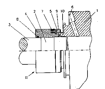
A device on an extruder for the evacuation of air, consisting of
a cylinder (1) with a die mounted at one end, the outlet, and a
piston (2) designed to move from a position outside the other end,
the inlet, to a position inside the cylinder. At the inlet, a
separate sealing device (11) is mounted which accompanies the
piston when it is retracted from the cylinder. The sealing device
consists of a casing (4) with sealing rings (8, 9) mounted on the
piston/piston rod (2, 3).


Claims

Note: Claims are shown in the official language in which they were submitted.

WO 93/11887 PCT/NO92/00191
Patent claims
1. Extruder for the evacuation of air, where the extruder
consists of a cylinder (1) with a die at one end, the
outlet, and a piston (2) designed to be moved from a
position outside the other end, the inlet, to a position in
the cylinder,
c h a r a c t e r i z e d i n t h a t
a separate sealing device (11) is provided at the inlet and
which is withdrawn with the piston when it is retracted from
the cylinder.
2. A device in accordance with Claim 1,
c h a r a c t e r i z e d i n t h a t
the sealing device consists of a casing (4) with sealing
rings (8, 9) mounted on the piston/piston rod (2, 3).
3. A device in accordance with Claims 1 and 2,
c h a r a c t e r i z e d i n t h a t
the casing (4) is provided with permanent magnets (7)
attaching it to the cylinder (1).
4. A device in accordance with Claim 3
c h a r a c t e r i z e d i n t h a t
the cylinder (1) is provided with a water-cooled steel ring
(4) against which the magnets impact.
5. A device in accordance with the above Claims 1-4,
c h a r a c t e r i z e d i n t h a t
the cylinder (1) is furnished with a bore (6) for the
evacuation of air, extending diagonally in a radial
direction from the inlet end of the cylinder and opening
into the inside of the cylinder.

Description

Note: Descriptions are shown in the official language in which they were submitted.


.
~ ~ /11887 1 PCT/N092tO0191
æn99256 :: ~
,. ~ .
~ SEALING DEVICE FOR THE PLUNGER OF AN EXTRUDER
The present invention relates to a sealing device for an extruder
for the evacuation of air, the extruder consisting of a cylinder
with a die and a reciprocating piston.
In the production of longitudinal metal sections by the
traditional method, a shaping machine of the above type is used.
A metal billet with a circular cross-section, is pre-heated and
~ placed in the cylinder. Then the piston presses the billet
;~¦ through the die with great force. The extrusions thus formed take
on different shapes depending on the shape of the hole in the
die.
Wor~ is being done to develop methods of producing metal sections
based on the use of particulate material such as metal powder or
needles. However, when one uses particulate material to make a
~; bolt or metal extrusion, there are increased problems with air
pockets and moist and this detracts from the quality of the
extrudate.
EP Patent Application No. 0397423 describes a method and
I equipment for producing metal objects by consolidation of
i - particulate material, using an extruder with a solution for the
evacuation of gas. A piston is used with a wedge, where the gas
1 is sucked out past the wedge and through a bore in the piston.
This solution gives an end product which is very close to optimum
- i.e. which to all intents and purposes is without deleterious
~ ~ - impurities and pores, and which has an almost impermeable surface
i~ which prevents absorption of humidity and gas during later use.
., ~

W093/11~7 ZQ PcT/Nog2/omgl ~
However, there is one disadvantage in the equipment described by ~ -
the above-mentioned Norwegian patent application - that it does
not achieve a satisfactory seal between the piston and the
cylinder, and this in turn means that air is drawn into the ~ -
cylinder during the extraction operation when a strong vacuum is
used.
'
Also known is an extruder where air is extracted from the
extruder cylinder by means of a ventinq plate which is pressed
against a venting ring mounted on the cylinder. The venting plate
can be moved by means of piston/cylinder mechanisms. This
solution is complicated and costly. In addition, it requires a
great deal of space and would obstruct the movements of anyone
operating it.
:
With the present invention a sealing device has been obtained for
; an extruder which provides an almost complete seal, and which,
combined with the use of an efficient vacuum pump, can provide
- ~ pressures lower than 103atm. The pressure can be further reduced
by using a ~olecular or diffusion pump. -
With this invention a sealing mechanism has been obtained for an
extruder which is characterized in that a separate sealing
1 -mechanism has been installed at the inlet, which sealing
mechanism accompanies the piston when it is retracted from the
3 cylinder, as defined in Claim l. ;
The subordinated Claims 2-5 define advantageous features of the
invention.
The invention will now be described in more detail by means of
i an example and references to the attached drawing, which shows
part of an extruder, in partial cross-section. It consists of a
cylinder l, a piston 2, and a sealing device ll. The die of the
extruder, the equipment for feeding the particulate material and
~i the hydraulic arrangement for moving the piston are not shown in
the drawing and will not be discussed in any more detail here.
~ .. .
.~ , .

~ ~ 3/11887 3 2 n 9 9 2 5 6 PcT/No92/oolg1
- The cylinder l is provided with a diagonally-placed radial hole
or bore 6 running from the feed end and opening into the
cylinder. The bore is furnished with a threaded steel pipe (not
; shown) which is in turn connected with a vacuum pump (not shown
either).
;' .
To obtain a seal between the'cylinder l and the-piston rod 3, a
sealinq device ll is installed outside the piston rod 3 and the
piston 2. see Claim l. This consists of a casing 4, mainly of
aluminium, furnished with an inside seal 8 against the piston rod
3, and a V-ring g in heat-resistant material as a seal against
the end of the cylinder l. On the front of the casing against the
cylinder a series of permanent magnets 7 is attached. The
permanent magnets keep the casing centred, i.e. in position in
relation to the cylinder until a vacuum arises in the cylinder in
connection with the extraction operation, which helps to press
the casing against the wall around the cylinder opening. In
addition, the permanent magnets - or rather the force they exert
- will help to make the piston, during its return movement, wedge
in an inside cone ll (sealing device and inside cone not shown in
the figure) on the casing 4 and will withdraw it to the starting
position. To improve the seal and reduce wear on the sealing ring
8, a lubrication arrangement (not shown) is provided for the
casing, which ensures that lubrication oil is supplied to the
area at the sealing ring. In addition, to prevent loss of
magnetic force at temperatures over 200C, a water-cooled steel
ring 3 is provided on the cylinder (at l0), against which the
magnets impact.
The evacuation device works as follows:
As long as the piston rod 3 with the piston 2 is outside the
cylinder l, the casing 4 with the magnets 7 will be wedged firmly
to the piston 2.
After the cylinder has been charged with a billet or particulate
material, the piston rod 3 with the piston 2 is inserted in the
cylinder l. The casing will be "held" in position by the magnets
.. ..
.: ~

W O 93/11887 PC~r/N 092/00191 ~
2099256 4 ~
as shown in the drawing and the air/gas can now be evacuated from
the cylinder through the vent bore 6. As the air is evacuated a
tighter seal is obtained between the cylinder/casing and
piston/casing respectively through the sealing rings 8 and 9, and
the casing will, as mentioned above, be pressed against the
cylinder. Trials have shown that a 100~ seal is achieved for a
pressure of 103atm. At the-end of the evacuation operation the
piston with piston rod moves on into the cylinder until the
extrusion cyFle has been completed.
j The evacuation mechanism as descri~ed in accordance with this
invention was in principle developed for use in connection with
the evacuation of air/gas when extruding particulate material.
However, the mechanism, as defined in the claims, can also be
used to evacuate air when extruding billets. It can further be
used in connection with an extruder to evacuate gas through the
piston as mentioned in the EP patent application referred to
initially in the specification.
.;~,, , , ,, :
,:
~ . :
.
,''~.
' :
..

Representative Drawing
A single figure which represents the drawing illustrating the invention.
Administrative Status

2024-08-01:As part of the Next Generation Patents (NGP) transition, the Canadian Patents Database (CPD) now contains a more detailed Event History, which replicates the Event Log of our new back-office solution.

Please note that "Inactive:" events refers to events no longer in use in our new back-office solution.

For a clearer understanding of the status of the application/patent presented on this page, the site Disclaimer , as well as the definitions for Patent , Event History , Maintenance Fee  and Payment History  should be consulted.

Event History

Description Date
Inactive: Dead - No reply to s.30(2) Rules requisition 2002-11-18
Application Not Reinstated by Deadline 2002-11-18
Inactive: Abandoned - No reply to s.30(2) Rules requisition 2001-11-19
Inactive: S.30(2) Rules - Examiner requisition 2001-05-17
Letter Sent 1999-08-05
Inactive: Application prosecuted on TS as of Log entry date 1999-08-05
Inactive: Status info is complete as of Log entry date 1999-08-05
Request for Examination Requirements Determined Compliant 1999-07-29
All Requirements for Examination Determined Compliant 1999-07-29
Application Published (Open to Public Inspection) 1993-06-24

Abandonment History

There is no abandonment history.

Maintenance Fee

The last payment was received on 2002-11-06

Note : If the full payment has not been received on or before the date indicated, a further fee may be required which may be one of the following

  • the reinstatement fee;
  • the late payment fee; or
  • additional fee to reverse deemed expiry.

Please refer to the CIPO Patent Fees web page to see all current fee amounts.

Fee History

Fee Type Anniversary Year Due Date Paid Date
MF (application, 5th anniv.) - standard 05 1997-12-08 1997-11-26
MF (application, 6th anniv.) - standard 06 1998-12-07 1998-11-17
Request for examination - standard 1999-07-29
MF (application, 7th anniv.) - standard 07 1999-12-07 1999-11-17
MF (application, 8th anniv.) - standard 08 2000-12-07 2000-11-14
MF (application, 9th anniv.) - standard 09 2001-12-07 2001-11-09
MF (application, 10th anniv.) - standard 10 2002-12-09 2002-11-06
Owners on Record

Note: Records showing the ownership history in alphabetical order.

Current Owners on Record
NORSK HYDRO A.S.
Past Owners on Record
KAI MAGNE VIK
LARS AURAN
OLE JOHAN SõRHEIM
Past Owners that do not appear in the "Owners on Record" listing will appear in other documentation within the application.
Documents

To view selected files, please enter reCAPTCHA code :


To view images, click a link in the Document Description column. To download the documents, select one or more checkboxes in the first column and then click the "Download Selected in PDF format (Zip Archive)" or the "Download Selected as Single PDF" button.

List of published and non-published patent-specific documents on the CPD .

If you have any difficulty accessing content, you can call the Client Service Centre at 1-866-997-1936 or send them an e-mail at CIPO Client Service Centre.


Document
Description 
Date
(yyyy-mm-dd) 
Number of pages   Size of Image (KB) 
Representative drawing 1998-11-13 1 9
Abstract 1995-08-17 1 50
Cover Page 1994-06-11 1 36
Claims 1994-06-11 1 62
Description 1994-06-11 4 205
Drawings 1994-06-11 1 45
Acknowledgement of Request for Examination 1999-08-05 1 193
Courtesy - Abandonment Letter (R30(2)) 2002-01-28 1 172
PCT 1993-06-25 11 360
Fees 1997-09-05 1 32
Fees 1996-12-04 1 57
Fees 1995-11-22 1 55
Fees 1994-11-09 1 61