Language selection

Search

Patent 2099304 Summary

Third-party information liability

Some of the information on this Web page has been provided by external sources. The Government of Canada is not responsible for the accuracy, reliability or currency of the information supplied by external sources. Users wishing to rely upon this information should consult directly with the source of the information. Content provided by external sources is not subject to official languages, privacy and accessibility requirements.

Claims and Abstract availability

Any discrepancies in the text and image of the Claims and Abstract are due to differing posting times. Text of the Claims and Abstract are posted:

  • At the time the application is open to public inspection;
  • At the time of issue of the patent (grant).
(12) Patent: (11) CA 2099304
(54) English Title: STRATA MOVEMENT INDICATOR
(54) French Title: DISPOSITIF INDICATEUR DE MOUVEMENT DE STRATES
Status: Expired and beyond the Period of Reversal
Bibliographic Data
(51) International Patent Classification (IPC):
  • G01V 9/00 (2006.01)
  • G01B 5/30 (2006.01)
(72) Inventors :
  • BLOOR, ALAN STUART (United Kingdom)
(73) Owners :
  • IMC GROUP HOLDINGS LIMITED
(71) Applicants :
  • IMC GROUP HOLDINGS LIMITED (United Kingdom)
(74) Agent: SMART & BIGGAR LP
(74) Associate agent:
(45) Issued: 1999-02-09
(22) Filed Date: 1993-06-28
(41) Open to Public Inspection: 1994-01-16
Examination requested: 1998-05-11
Availability of licence: N/A
Dedicated to the Public: N/A
(25) Language of filing: English

Patent Cooperation Treaty (PCT): No

(30) Application Priority Data:
Application No. Country/Territory Date
92 15082.0 (United Kingdom) 1992-07-15

Abstracts

English Abstract


A strata movement indicator includes at least two lengths of
suspension wire respectively for remote and near anchors locatable
in the same borehole. Each wire carries a cylinder provided with
indicator markings, the cylinders being moveable with respect to
one another and to a reference tube fixed in the mouth of the
borehole. Relative movement of the cylinders with respect to one
another and/or to the reference tube indicates the degree of strata
movement.


French Abstract

Dispositif indicateur de mouvement de strates comprenant au moins deux longueurs de câble de suspension respectivement pour dispositifs d'ancrage à distance et rapprochés localisables dans le même trou de forage. Chaque câble comporte un cylindre fourni avec des marques d'indication, les cylindres sont mobiles à l'un et par rapport à l'autre et par rapport à un tube de référence fixé à l'entrée du trou de forage. Le déplacement relatif des cylindres l'un par rapport à l'autre et par rapport au tube de référence indique le degré de déplacement des strates.

Claims

Note: Claims are shown in the official language in which they were submitted.

THE EMBODIMENTS OF THE INVENTION IN WHICH AN EXCLUSIVE
PROPERTY OR PRIVILEGE IS CLAIMED ARE DEFINED AS FOLLOWS:
1. A strata movement indicator for use in association
with a borehole formed in strata, the indicator including at
least two flexible elongate suspension members, anchors for
anchoring the suspension members at spaced apart locations in
use within the borehole formed, a guide through which the
members pass, the guide being fixable in use within the
borehole, and a cylindrical indicator element held on each
suspension member and movable in relation to the guide and to
one another in the manner of a piston, the movement of each
element being indicative of strata movement.
2. An indicator according to claim 1 in which each
flexible elongate suspension member is a length of wire cable.
3. An indicator according to claim 1 in which each
anchor is a wire torsion spring engageable directly with the
wall of the borehole.
4. An indicator according to claim 1 in which the
guide is a short tubular sleeve extending in use a short
distance within the borehole.
5. An indicator according to claim 4 in which the
sleeve is split longitudinally thereof and is in use sprung
into the borehole and frictionally fixed therein.
- 7 -

6. An indicator according to claim 1 in which each
indicator element is marked to indicate the degree of movement
relative to the guide.
7. An indicator according to claim 6 in which each
indicator element is marked with chromatic banding.
8. An indicator according to claim 1 in which the
cylindrical indicator element on one suspension member is
mounted to slide within the cylindrical indicator element of
the other suspension member.
- 8 -

Description

Note: Descriptions are shown in the official language in which they were submitted.


~Q~3~
-- 1 --
STRATA MOVEMENT INDICATOR
This invention concerns a strata movement indicator.
The present invention has particular, but not
exclusive, reference to an indicator for use in underground
mines, for example coal mines, in association with rock bolted
strata.
The rock bolting of strata defining roadways or
galleries in underground mines has long been known and applied
dependent upon the nature of the strata and the method of
working the mineral seams. Although it has found widespread
application for example in the United States, it has not been
until more recent times that it has found favour in the United
Kingdom and Europe where more conventional supports, for
example arches, have predominated. By virtue of their
distortion or displacement, such supports give a readily
observable indication as to the manner is which movement
within the surrounding strata in taking place.
However, when employing rock bolts alone for
reinforcement, because they are embedded within the strata
there is no readily external visual indication as to the
movement of the strata.
In the applicant's British Patent No. GB 2253703
which has a filing date of March 13, 1991 a simple yet
effective strata movement indicator is described which
includes the features of an anchor at the remote end of a
borehole and a reference tube at the near end of the same
borehole. The anchor is connected to a banded indicator by
23479-174
,1'~'

-
3 ~ 4 -
- la -
means of a wire. Expansion of the strata causes the indicator
to mover relative to the reference tube by an amount equal to
the net expansion between the anchor and the reference tube.
Whilst the indicator performs satisfactorily, it is incapable
of focusing upon the source of the strata movement.
23479-174
.,~

3 ~ ~
It is an object of the present invention to provide
an improved strata movement indicator.
According to the invention a strata movement
indicator includes at least two flexible elongate suspension
members, anchors for anchoring the suspension members at
spaced apart locations in use within a borehole formed in the
strata, a guide through which the members pass, the guide
being fixable in use within the borehole, and an indicator
element held on each suspension member and movable in relation
to the guide and to one another in the manner of a piston, to
movement of each element being indicative of strata movement.
Each flexible elongate suspension member may
conveniently be a length of wire cable, and each anchor may be
a wire torsion spring engageable directly with the wall of the
borehole.
The guide may be a relatively short tubular sleeve
extending in use a short distance within the borehole and may
be split longitudinally affording a spring effect, whereby the
sleeve may be sprung into the borehole and frictionally fixed
therein.
Each indicator element may be cylindrical in form
and slidable in the manner of a piston relative to the guide.
The indicator element is preferably marked to indicate the
degree of extension/retraction thereof within the guide and
thus the degree of strata movement. The marking may be
achieved by the use of chromatic banding, conveniently the
colours being red, orange, and green to represent the degrees
of strata movement, red being indicative of a potentially
-- 2
23479-174(S)
k

3 ~ 4
dangerous condition in which urgent and substantive action is
required to avoid failure of the roadway, green representing
an acceptable condition, and orange indicating an interim
condition in which moderate remedial action needs to be taken.
The indicator element for the anchor located
remotely from the mouth of the borehole may be of relatively
smaller size than that
- 2a -
. 23479-174(S)

2099304
- 3
for the anchor nearer the mouth, the one being slidable within the
other and within the guide in the manner of pistons.
The invention includes the provision of more than two anchors for
disposition in the borehole at spaced apart locations therealong,
together with the same number of indicator elements to provide
indications as to strata movement along the length of the borehole.
By way of example only, a strata movement indicator according to
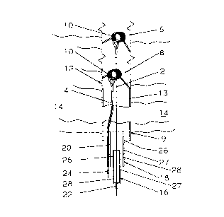
the present invention is described below with reference to the
accompanying drawing which is a diagrammatic view of a borehole
with a strata movement indicator in situ within the borehole.
"
Referring to the drawing a strata movement indicator includes two
suspension wires 2, 4 connected respectively to a remote anchor 6
and a near anchor 8, each anchor being in the form of a coil spring
10. The anchors 6, 8 are fixedly located in a borehole-12 in
strata 14 at spaced locations therealong.
The indicator further comprises a guide in the form of a reference
tube 13 secured in place within the mouth 9 of the borehole 12.
Suspended respectively on each wire 2, 4 is an indicator element in
the form of a cylinder 16, 18 the cylinder 16 being of smaller
diameter than cylinder 18 and being slidable therewithin. The
larger diameter cylinder 18 is slidable within the reference tube
13 and carries a guide 20 on its outer surface for the suspension
wire 4 in order that it may be kept separate from the wire 2 and to
provide a suspension point. The cylinders 16, 18 are held on
their wires 2, 4 by ferrules 22, 24.
Each cylinder 16, 18 has on its outer surface colour bands, 26, 27
and 28 being respectively green, orange and red.
In practice the strata movement indicator of the present invention
is emplaced in the following manner, given that the borehole 12

.~ 2~ 3 ~ 4 ~
has previously been formed in the appropriate location, for
example adjacent to a heading in a roadway in which rock
bolting has been or is in progress. The reference tube 13 is
first inserted into the borehole 12 and pressed home to sit
firmly within the mouth 9 of the borehole 12 partially proud
thereof. An insertion rod (not shown) is used to introduce
the anchor 6 connected to the wire 2 through the tube 6 and
into the borehole 12. With a slight tension on the wire 2 the
insertion rod carries the anchor 6 to a position adjacent the
inner end of the borehole 12 and there engages the wall of the
borehole in sprung frictional fashion.
The insertion rod is used again to introduce the
anchor 8 connected to wire 4 through the tube 6 and into the
borehole 12. With a slight tension on the wire the insertion
rod carries the anchor 8 to a position intermediate the inner
end of the borehole 12 and the mouth 9 thereof.
The guide 20 of cylinder 18 of the indicator element
is threaded onto the wire 4 which passes through the reference
tube 13 until the top of the green band 26 aligns with the
bottom edge of the tube 13. The ferrule is then crimped to
the wire 4 beneath the cylinder 18 to hold the cylinder in
that initial position. The cylinder 16 of the indicator
element is threaded onto the wire 2 which passes through the
cylinder 18 and the tube 13 until the top of the green band
aligns with the bottom edge of the cylinder 18. The date and
time of installation of the strata movement indicator are then
recorded together with the length of the borehole drilled in
order to establish a datum against which any movement of the
-- 4
23479-174(S)

~ O ~ ~ 3 ~ 4
strata can be monitored.
As dilation of the strata occurs due inter alia to
the working of the mineral seams within the mine environs, the
anchors 6, 8 will accordingly move and respectively carry the
cylinder 18 further into the reference tube 13 and/or carry
the cylinder 16 into the cylinder 18 thus obscuring the colour
bands on the cylinders sequentially dependent upon the
severity and extent of the strata movement.
Interpretation of the movement of the indicator is
important and for simplicity the meaning of the change in
relative position of the two cylinders 16 and 18 and the
reference tube 13 is given below.
In the event of there being expansion of the strata
14 beyond the remote anchor 6, the indicator will give no
indication thereof, the relative positions of the cylinders 16
and 18 and the reference tube 13 remain unaltered.
If there should be expansion of the strata between
the remote anchor 6 and the near anchor 8, the cylinder 16
moves into the cylinder 18 which latter remains in the same
position relative to the reference tube 13.
Upon expansion of the strata between the near anchor
8 and the reference tube 13, the cylinder 18 moves in relation
to the reference tube 13 whilst the cylinder 16 remains
stationary.
If there should be expansion throughout the length
of the borehole 12, the cylinder 18 moves into the reference
tube 13 by an amount equal to the expansion in the nearer part
of the borehole 12, namely between the near anchor 8 and the
-- 5
23479-174(S)

~ Q ~
mouth 9 of the borehole 12. At the same time, the cylinder 16
moves into the reference tube by the total amount of expansion
in the borehole 12. The total is more easily assessed by
adding the movements of the two cylinders.
In each of the above cases the degree of strata
movement can be visually detected by inspection of the
chromatic banding on the cylinders 16 and 18.
The indicator of the present invention thus provides
a relatively simple and yet effective way of determining the
strata movement in a mine environment. Whilst the invention
has been described in relation to an indicator having two
anchors and thus two indicator
- 5a -
23479-174(S)

2099304
- 6
elements, it is to be understood that more than two may be
employed. Any limitation on the number of indicator elements will
be dictated by the practicality of accommodating the same in the
one borehole.

Representative Drawing
A single figure which represents the drawing illustrating the invention.
Administrative Status

2024-08-01:As part of the Next Generation Patents (NGP) transition, the Canadian Patents Database (CPD) now contains a more detailed Event History, which replicates the Event Log of our new back-office solution.

Please note that "Inactive:" events refers to events no longer in use in our new back-office solution.

For a clearer understanding of the status of the application/patent presented on this page, the site Disclaimer , as well as the definitions for Patent , Event History , Maintenance Fee  and Payment History  should be consulted.

Event History

Description Date
Time Limit for Reversal Expired 2007-06-28
Letter Sent 2006-06-28
Inactive: IPC from MCD 2006-03-11
Grant by Issuance 1999-02-09
Inactive: Correspondence - Prosecution 1998-11-17
Inactive: Final fee received 1998-11-09
Pre-grant 1998-11-09
Notice of Allowance is Issued 1998-09-18
Letter Sent 1998-09-18
Inactive: Approved for allowance (AFA) 1998-09-08
Inactive: Status info is complete as of Log entry date 1998-09-08
Inactive: Application prosecuted on TS as of Log entry date 1998-09-08
Advanced Examination Determined Compliant - paragraph 84(1)(a) of the Patent Rules 1998-06-02
Letter sent 1998-06-02
Request for Examination Requirements Determined Compliant 1998-05-11
Inactive: Advanced examination (SO) fee processed 1998-05-11
All Requirements for Examination Determined Compliant 1998-05-11
Inactive: Single transfer 1998-02-09
Application Published (Open to Public Inspection) 1994-01-16

Abandonment History

There is no abandonment history.

Maintenance Fee

The last payment was received on 1998-06-23

Note : If the full payment has not been received on or before the date indicated, a further fee may be required which may be one of the following

  • the reinstatement fee;
  • the late payment fee; or
  • additional fee to reverse deemed expiry.

Please refer to the CIPO Patent Fees web page to see all current fee amounts.

Owners on Record

Note: Records showing the ownership history in alphabetical order.

Current Owners on Record
IMC GROUP HOLDINGS LIMITED
Past Owners on Record
ALAN STUART BLOOR
Past Owners that do not appear in the "Owners on Record" listing will appear in other documentation within the application.
Documents

To view selected files, please enter reCAPTCHA code :


To view images, click a link in the Document Description column. To download the documents, select one or more checkboxes in the first column and then click the "Download Selected in PDF format (Zip Archive)" or the "Download Selected as Single PDF" button.

List of published and non-published patent-specific documents on the CPD .

If you have any difficulty accessing content, you can call the Client Service Centre at 1-866-997-1936 or send them an e-mail at CIPO Client Service Centre.


Document
Description 
Date
(yyyy-mm-dd) 
Number of pages   Size of Image (KB) 
Description 1998-08-25 9 245
Claims 1998-08-25 2 48
Abstract 1994-03-05 1 11
Cover Page 1994-03-05 1 13
Description 1994-03-05 6 171
Claims 1994-03-05 1 28
Drawings 1994-03-05 1 21
Cover Page 1999-02-05 1 40
Representative drawing 1999-02-05 1 8
Representative drawing 1998-08-17 1 18
Courtesy - Certificate of registration (related document(s)) 1998-05-22 1 117
Commissioner's Notice - Application Found Allowable 1998-09-18 1 166
Maintenance Fee Notice 2006-08-23 1 173
Fees 2003-05-16 1 35
Correspondence 1998-11-09 1 32
Fees 2005-04-08 1 33
Fees 1997-02-10 1 54
Fees 1996-03-21 1 46
Fees 1995-05-01 1 52
Courtesy - Office Letter 1998-06-02 1 12
Examiner Requisition 1998-06-09 1 46
Prosecution correspondence 1998-08-10 3 100
Prosecution correspondence 1998-06-03 1 30