Note: Descriptions are shown in the official language in which they were submitted.
2~9~0
ethod and_ devics for the anaerobic d~ecommposition
_~qanic waste.
~: 5
The pre~ent invention concerns a method for the an~erobic
decomposition of degradable organic waste and for the
extraction of biogas from the latter in a reac~or,
according to which method the ~aste is put in ~ reacto~
..10 which contains an active, anaerobic, methanogene biomass
a~ which is exposed to anaerobic ferment~tlon without
any mix.ing in the reactor.
By degradable organic waste i~ meant in particular the
~` 15 organic ~r~ction of domestic or bi.ological was~e or
. similar organic fractions-.such as sludge, industrial
., organic waste, etc.
According to the known methods for the decomposition of
~, 20 domestic solid waste, or similar sQlid waiste, water is
added to the organic fraction of khe solid ~aste, such
that pulp is obtained containing 10 to 12% solid matter
~: which is decomposed in an anaerobic mannerO The waste is
regularly supplied- to a reactor ~or anaerobic
decomposition in which the concentration of solid matter
~3i amounts to 4 to 8% and in which the waste is decomposed
:for 10 to 30 days at a temperature of about. 35 to 50
degrees Celsius. The content of the reactor is regularly
mixed, such that the freshly supplied waste makes contact
30 ~: with the already decomposed residue in the reactiDr. --.
~ :, :
; :With such methods, thorough mixing is important, such
tha.~ the supplied waste i5 evenly distributed in the
: reactor~and the methane bacteria make contact with their
~:nutrients. Thus, the formition of inac~ive zones in the
:reactor:can be avoided,
~ ,
~9~
The concentration of dry matter, however, is limited ln
~hese entirely mixed, anaerobic reactors to about 8% at
th~ most. This is mainly due to crustation~ as a result
of which ths mixing is ineffective, and consequently
5 inactive zones are formed or the reactor acidifies.
Consequ~ntly, the gas production is limited to 1 to 1.5
m3 biogas per m3 waste per day.
Mixing and crustation problem~ in the treatment of the
.` 10 organic part of domestic waste, similar solid waste or
~ semi solid substrates and the ensuing low load level of
- the reactor and restricted gas production can be avoided
by making u~e o~ dry or liquid two-phase, highly-
efficient decomposition devices.
15 Dry anaerobic, highly efficient decomposition devices
work with a ~olid concentration wherPby no crustation or
'. phase-separation takes place, and whereby th~ mixing is
done by removing the content of the reactor from this
reactor and by mixing it in an appropriate mixing devlce
20 with supplied nutrient substrate and by subaequently
., pumping the mixt-ure back in the reactor. By using high
concentrations of solid matter, phase separation, and
consequently crustation~ is avoided and the production of
biogas with a high output of 6 to 8 m3 biogas per m3 waste
25 per day is possiblè. In fact, one could say that these
devices work ~ith the crust itself.
;l
.The dry anaerobic composting method, as de~cribed i~ EP-
A-O 131 319 and EP-A-O 205 721 Bl, whereby the organlc
fraction of the domestic waste is decomposed with a
~ concentration of totally solid matter of 25 to 45%, i8
t~ for example bas~d on a thorough re-circulation of two
~,
thirds of the matter which was taken out of the reac~or. ~:
his recycIed material is the~ mixed as inoculum with an
:amounk of fresh organic material equal to 1eS6 than half
;:~: of this recycl0d amount. However, thi~ method i5
: ,
2~ $~
~specially suited for dry, solid substrate5, such khat a
high concen~ratio~ of svlid matter can be maintained in
the reactor.
.,
Liquid, two-phase, highly efficient decomposition
devices, as opposed to the ab~ve-mentioned dry
decomposition devices, work with a very low concentr~tion
of totally solid matter in th~ methanogene phase, and
make use of a sludge bed reactor or other types of
anaerobic reactors with a high water level or the
treatment of waste waters with ~ low concentration of
suspend~d solid matter. .. -~
'''~
In the~e devices, the org~nic fraction of the domestic or
organic waste is preliminary treated in a shredder and
hydrolysis tank, such that the biologically degradable
fraction i6 made as liquid as po~sible. This preliminary
kreated fraction is ~eparated by means of a press or
other dehydrating mean~ from the remaining solid mattçr,
and the liquid containing less than 2 to 3% tstally solid
matter and whose solid matter is preferably dissolvable
for more tha~ 80~, is ~ubsequently decomposed in an
anaerobic upward sludge bed or similar r~act~r. This
method i3 more suit-ed ~or the easily hydrolysable and
biologically degradable fraction of domestic waste, which
:~ : is also the most humid fraction of the domestic waste.
.
~ he invention concerns a new method for anaerobic
:~~ decomposition which is applicable to organic was~e such
as the organic fraction of domestic or ~iological waste
or similar organic fractions such as sludge, industrial
organic waste, çtc., and which is also suited for the
d~composi~ion of oth~r was~e ~han dry solid su~strates or
the fraction of domestic waste which can be easily
hydrolysed, ~but which neverkheless ca~ be highly
::efficient.
:.
:
To this aim the waste is supplied in the ~hape of a semi
solid or 501id organic substrate at the top of the
reactor, a phase separation into a liquid and solid pha.se
i5 allowed ln the lower part of the reactor, whereby at
least during a fermentation period wlthout any mixing in
the reactor, a liquid phase is secreted at the bot-tom in
the reactor from an upper solid phase, this liquid phase
is removed before fresh substrate is supplied, whereby a
maximum amount of ~olid phase, namely isubstrate and
biomass, is retained, and, after the removal of the
: liquid phase, the solid phase is removed from the reactor
to at least one third of the entire con~ent of the
reactor and thoroughly mixed with frei~h substrate a~
inoculum.
: 15
I The dry reactor can provide a high output without any
.-. internal mixing and a with a high concen~ration of solid
.;;, matter, without it being required to maintain the
` concentration of solid matter at levels of 2-5 to 40 ~ for
"fi 20 extraction and ~ermentation purposes as is the case wi~h
the known dry anaerobic decomposi-~ion method. As opposed
`'f, ' to this known dry anaerobic decomposition method, phase
separation or crustation is allowed in this reactor.
~ Said phase separation is used to r~move all redundant
.~' 25 liquids from the reactor, such that the reactor can work
:I - with a humid and biologically highly degradable
:~j `substrate~ but also wi~h a high concentration of solid
~! matter. If similar substrates were treated in a reactor
with a high percentage of solid matter, material should
be removed from the reactor and dehydrated to r~move the
: . surplus o~ water and to maintain th~ concentration of
solid matter in the reactor at 25 to 40%.
J ~
~ : The method according to the invention is al90 diff~rent
',;:;a ~ :35 from liquid~ two-phase, highly-eficient deviceis in that
I ~ thè separation is carried out .in one single tank and in
, ,
$ ~
tha~ the phase separat.ion i~ ob~ainfed by a natural
phenomenon at the bottom of the reactor and not through
~ifting or d~hydration. In th~se liquid, two-pha~e,
highly efficient devices, the flrst phase is used for
:5 hydrolysis of the solid matter, after which the solid
matter is removed and the liquid is exposecl to an
anaQrobic sludge bed with a high output or any other type
of liquid reactor with a high output. According to the
invention, the hydrolysis and anaerobic degradatiGn t~ke
place in the concentrated top part, and the phase
separation or the removal of the redundant waterf
required to maintain a co~centrated decomposition, takes
-place by removing liquid after a natural phase separation
at the bottom in the reactor.
Preferably, the amount of fresh ~ubstratf~ is practically
equal to the amount o~ liquid phase which has been
removed from the reac~or, increased by the amoun~ which
disappeared during the formation of said phas~ as biogas.
According to a special embodiment o~ the i~vention, the
ph~ e 6eparation is allowed in ~he lower part of the
~reactor, preferably- in the lowfer 0 to 20% of this
reactor.
According- to a peculiar embodiment of the invention,
waste is supplied having such a percentage of dry ma~er
that the percentage of dry matter of the content of the
~::30 reactor, prior to the phase separation, is situated
bétween 15 and 35 %.
~:The organic waste to be decompofsed can be supplied as
such directly to -~he reactor. However, it is al~o
pos~slble that the waste supplied at the top of the
reactor is ~omposed by mixing solid or semi-solid was~e
.
:
with waste water.
~ccording to this embodiment the waste water is treated
simultaneously with the ~emi~solid or solid organic
substra~e, such that both the anaeroblc disintegration of
the solid or semi-solid nutrition and the ana~robic
reduction o~ the pollution in the waste water flow takes
place.
: 10 The invention al60 concerns a device which is
particularly suited for the embodime~t of the m~thod
according to any of the above embodiments.
Thus, the lnvention concerns a device or the anaerobic
decomposition of organic waste contained in a ~acuum
^ reactor, a supply device conn~cted to the top o~ the
reactor for the supply of organic matarial to be
decs:mposed~ a discharge device connec~ed to the bottom o:f
~, the reactor for the discharge of the solid residu~ a~d a
mixiny device for mixing the discharged residue with
fresh organic material, which is characterized in -that
the reactor contains a discharge device for discharging
~, a liquid phase at the bo~tom of the reactor.I
Preferably, the device contains filter means which are
- mounted at the bottom in the reactor so as to stop the
solid phase as the liquid phase is discharged.
.: ~
Practically, these filter means consist of partitions
directed from the bottom to the top which are provided
with passages, whereas the discharge device for the
:l; liquid phase contains ~i~charge pipes to which said
; partitions lead.
In order to better explain the characteristics according
~to the inven~ion, æome preferred embodiments of a me~hod
: : ,
2 ~ ~ 9 ~
; and ~evice for the anaerobic decompoi~ition o~ or~anicwaste are described below by way of example only and
without being limitativ~s in any way, with reference to
~`~ the accompanying drawingis, wher~:
figur0 1 is a schematic repres~ntation o~ a device
for the an~e~obic decomposition of organic waste
according to the invention;
fiyure 2 shows a section according to line II-II in
figure 1~
figure 3 shows a section according to line III-III
; in i~ur~ 2, to a larger scale.
1 15
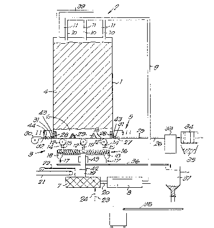
; The device represented in ~igure 1 mainly contains a
'~ closed reactor 1, a supply device 2 for the nutrition o-f
~ th~ reactor 1, a discharge device 3 for the solid
.~ residue, being the solid fermented phase 4, a discharye
device 5 for the liquid residue of the liquid phase 6 and
;1 a mixin~ devic~ 7, which is moun~ed between the supply
~ device 2 and the discharge device 3, for the mixing of
:!1 the fermented solid waste 4 with fresh organic material
,3 to be decomposed. --
~ 25
i~ The ~upply device 2 con~ists of a displacement pump 8 and
a supply pipe 9 which, via rami~ications 10 provided with
automatic valves 11, runs into the upper fiide of the
reactor 1 at different places.
~: .
The discharge device 3 for the solid phase 4 contains a
3;~ number~ of screw jacks 12 which are erected oppo~ite
grooves 13 in the hottom of the reactor 1 and which, via
ducts 14 provided with valves 15, lead to a central
3~ diqcharge screw jack 16~ Depending on the ~ense o
3~
rotation, said pump pump~ towards both ends, where
outlets 18 shut by valves 17 are normally connected, or
to the centre, where a central discharg~ pipe 19 is
connected, wh.ich conn2cts the jack 16 with the mixing
device 7 and which can be shut by means of a valve 42.
The mixing device 7 is connected to the displacement pump
~ with its discharge pipe 20, whereas an endless conveyor
b~lt 21 f~r fresh organic material leads to said mi~lng
device 7, and a supply pipe 22 for the possihle supply of
waste water to the mixing device 7 and a steam piping 24
which can be shut by means of a valve 23 ru~ into said
device 7.
Th~ discharge device S for th li~uld phase 6 contains a
discharge pipe 26 which can be shut by means of a valve
25, which is connected to a closed ring line 27 which
surrounds the bcttom of khe reactor 1 and which leads to
the bottom of the reactor 1 via filters 28 and 29. The
filters 28 are built in upright in the wall o~ the
reactor, whereas the filters 29 are sheets provided with
openings which stand two by two at the boktom of the
reactor sloping a~ a hood and which ~orm a space which
reaches to the reactor wall with both ends. Said two
ends and ths filters 29 lead via pipes 43 which can be
- shut by mean~ of valves 31 to the ring line 27~ as
represented in detail in figure 3. In order to freely
rinse the filters when they are obstructed, a rinsing
: pipe 32 connected to a pump 30 and which can be shut by
30 means of a valve 44 is connected to the ring line ~7. . -
:~ The discharge pipe 26 i~ connected to a pres~ filter 34
: or another water treatment device via a storage tank 33.
Remaining solid parts are collected in a reservoir 35O
The storage tank 33 can be provided for the application
of an anaerobic fermentation or nitrificat.ion for a
: ~ certain time.
~: ' .' :.
: ~ :
Under the outlet6 18, a conveyor belt 36 is erected which
leads to a settling tank 37, from where the sediment can
b~ discharged to a water tr~atment devic0 via a conv~yor
belt 38 and the liquid phase.
. 5
At the ~op, a discharge pipe 39 for biogas is connec~ed
. to the reactor 1.
.,
, The device operates and is used as follows:
1 0
When the device is started up, the reactor 1 is filled
via the supply device 2 with anaerobic inoculum. Sald
înoculum may be provided ~y a well workiny anaerobic
reactor with a hiyh percentage of solid matter such as a
.; . .
reactor described in patent EP-A-O 131 319, or ît can be
made by dehydrating the fermente~ residue of a well
working, en~irely mixed anaerobic reac~or which
I preferably decomposes the organic fraction of household
waste, æewer sludge, manure, biomass or any other organic
substrate, or on the basis of the sludge of an upward
flow sludge bed reac~or which purifies waste wat~r under
anaerobic circumstances. The inocu].um contains common
a~aerobic micro-organisms such as species of
: Methanosarcina, ~ethanothrix, Methano~oenghenii, etc. for
anaerobic decomposition. The inoculum contains at least
15~ and preferably 25 to 35% totally solid mat~er. The
I amount of inoculum to start with is preferably as large
as possible, preferably sufficient to fill the entire
~: content of ~he reactor 1. The inoculum is hea~ed up to
m2sophile temperatures (35 to 40 degrees Celsius~ or
: thermophile temperatures (50 to 55 degrees Celsius).
Then the inoculum is removed again from ~he reactor by
; meani of the discharge device 3, thoroughly mixed in the
mixing device 7 with preferably not more than 10 to 20
~:: 35 weight % o the organic material to be deccsmposed whose
size has preferably been reduced during a pr~liminary
`:
~ ' .
treatment, which has been supplied via the conveyor belt
21 and has been brought back in the reactor 1 by the pump
8 via the pipe 9 and the ramifications 10, where ~ne
substrate is left alone.
Due to the highly acti~e bacteria in the inoculum, the
skatic decompo6ition immediat~ly takes place in the
reactor 1 without any mi~ing and the natural phenomenon
of phase separation into a solid phase 4 at the top and
a liquid phase 6 in the lower part/ pref2rably the lower
0 to 20~ of the reactor 1, is tarted. This phenomenon
is not hindered in any way, but on the contrary allowed.
After one or several hours, dependiag on the nature of
the substrate and the percentage of dry matter in the
lS solid phase ~, ~he secretion of liquid phase 6 has
advanced sufficientl~, such that said phase can be
discharged.
Said extraction of liquid phase is started by opening the
valves 25. The extraction takes place in various places
at the bottom of the reactor 1 through the filters 28 and
29 which stop as much solid matter as possible in the
liquid phase, such that a liquid with a minimu~ amoun-~ oF
suspended solid ma-tter is discharged. This liquid is
carried to the storage tank 33 which may be provided ~o
- allow for an anaeroblc fermentation to further purify the
liquid or to allow for a nitrification, possibly a
denitrification, therein to reduce the amount of ammonium
~: n.itrogen and the amount of nitrates respectively. The
low-nitrogen l.iquid can then be carried back to the
reactor 1 via the pipe 22.
After the extraction of t.he liquid pha~e, an amoun~ of
fresh organic material, whose weigh~ is about equal to
th amount of liquid which was removed, increased by the
amount of material which has been removed via the biogas,
~96~
11
is supplied to the mixing device 7 via the conveyor belt
21 and subsequently mixecl with a part; namely 1/3 of the
total amount of material, i.eO the solid phase which
remains in the r~actor l with regard to the to~al amount
of said material, for example wi~h half of the solid
phase in ~he reac~or or with the entire solid phase .in
the reactor. The weigh~ proportion of th~ materi~l from
the reactor 1, which is in fact the inoculum, to thP
amount of fresh organic material may be higher than 3.1
and may be situated for example between 8:1 and 10:1.
This part vf the solid phase is supplied in the mixing
device 7 by means of the screw jacks 12 and the central
screw jacks 16 via the central di~charge pipe 19.
The percentage of dry m~tter of the mixture is situated
between 15 and 40~ and preferably between lS and 35%.
Within these limits, an amount of waste water or ordinary
water may be supplied to the mixing d~vice 7 via the
supply pipe 22 if required. Preferably, water or waste
20 water with a low percentage o:f nitrogen and salt~ i~
~dded, such that during the subsequent phase eparation
the po~sible excess o:f nitrogen and sal~s from the :Er~h
organic material ends up in ~he liquid phase, which
promotes the disintegration.
In case of a high amount of nitrogen in the solid phase
the liquid phase can be partly nitrified, possibly
. denitrified in the storage ~ank 33 and supplled again to
: the reactor 1 via the pipe 22 and the pump a. In this
way, exce~s nitrogPn from the solid phase 4 is extracted.
Af~er the nitrificationjdenitrification the liquid phase
may also be centrifuged or pressed, after which only the
: low-nitrogen cake from the centrifuge or, when a press is
used, the pressed cake is recycled towards the reactor 1.
: 35
:: ~ :
~ : '
:
.
.
2 ~ 0
12
By adding s team via the r~i~eam plpe 24, the mixture in ~he
mixing device 7 is heated up to 35-40 or 50-55 deigreg~s
:~ Celsius.
5 The mi~cture is pumped into the reactor 1 -~rom th~ mixi.ng
clevice 7 via the pipe 9 and thlo ramifica~ion~ 10 through
the pump 8. The di.scharge device 5 is closed and the
; valve 25 is shut. Also the discharge device 3 is
inopeirative and the screw jacks 12 ar~ ou~ of ac~ion.
: 10 The content of the reactor 1 is le~t be, for example for
one night, whereby a separation into a liquid phase 6 in
the lower part, preferably the lower G to 20%, and a
solid phase 4 on top o-f it again ~akes place.
Afterwards, said liquid phase 6 is discharged from the
reactor 1 in ~he manner described abov~j? and subsequeintly
at least one third of the con~ent of the r~actor 1 of
solid phai~e 4 is put from the reactor 1, also as
described above, into khe mixing devic2 7 and mix~d thare
with about the same amount of fresh organic material a~
;~, 20 the amount of discharged liquid phase and biogas.
.' .
J The above-mentioned stages are then successively
repeated, whereby rom time to time, for e~ample once a
l week, right after an extraction of the solid phase 4, a
¦ 25 rinsing of the screw jacks 12 ~ind 16 is carried out, such
that theré i~ no solid phase anymore so that, during thie
following phase separation, these pumps will be fill~d
¦ i with liquid phase 6. Hereby, also heavy particles Such
i as glass, metal, etc. which are present in the reactor 1,
3Q will settle and end up at the bottom of the reactor and
. in said screw jacks 12 and 16. By subsequently driving
the ce~tral screw jack 16 such that it pumps ~owards the
outlets 18, these heavy particles can be discharged ~ia
: said outlets 18, whose valve 17 was temporarily opened.
These particles are collected on the conveyor belt 36 and
transported to the settling ta~k 37 to which, if
,: .
! ~
13
required, liquid :Erom the storage taIlk 33 can be add~d so
as to ob~ain a good s~dimentation and separa~ion.
The sediment of the tanls 37 is discharged via the
5 conveyor belt 38. The discharged liquid phase 6, which
~till con~ains a percentage of dry matter of 2 to 5%l is
carried via the discharge pipe 26 to the storags tank 33
and from there via the press -filter 34 or via other
suitable equipment to a watar treatment device. The
pressed cake is collected in the reservoir 35 and
posslbly further re-compost~d in an aerobic manner.
The filters 28 and 29 in the ~all and at the bottom of
the reactor ar~ self-cleaning because the liquid flow, as
indicated by the arrow 40 in figure 3, is horizontal
during the extraction, whereas during the removal of the
solid phase 4 from the reactor, the flow runs vertically,
as indicated in figure 3 by the arrows 41. This implies
that the particles of a layer of solid matter which are
retained ~y the vertically or slan-tingly erected filters
28 and 29 are removed during the liquid extrac~io~ by th~
downward movement of the solid phase during the
extraction of said solid phase.
On the central screw jack 16 may be mounted a double-
walled cage with filter means 45, as indicated in f.igure
1, such that also the liquid phase 6 can be extracted via
~: thi~ cage 45. The central screw jack 16 can be built
. .
;~ such that a pressure i5 created in i~ such that ~xtra
: 30 liquid is pressed through the cage with filter means 45
during the extraction of ~he solid phase 4. Al o, during
: the phase separation, secretion of the liquid phase 6 may
; take place via this cage if the screw jack 16 is
su~ficiently discharge~ :of solid phase 4 and contains
mainly l.iquid phase 6.
::
.
2 ~
14
E~tr~ filter mean~ 3uch as cay~s 45 ca~ be mount~d around
- the screw jacks 12 for the extractio~ of the liquid pha~e
6. Such ca~es are only represented in figure 30
Also the filter means 45 are self-cleaniny thanks to the
two different directions of the liquid phase 6 and the
~ solid phase 4 respectively. If such filter mean~ 45 are
; pro~ided, i~ is possible to leave the extraction fil~ers
29 out, in which case the bottom o the reactor 1 is flat
and a slide fri~me as described in EP-~ 0 205 721 can be
; mounted such that i~ can slide to and ~ro so as to push
the solid phase 4 in the grooves 130
Should the filters 28 and 29 become obstruct~d, they can
~` 15 be cleaned by pumping liquid counterflow through the
filters by m~ans of the pump 30 ~ia the rinsing pipe 3~
i with temporar;.ly opened valve 31/ whereby by shutting the
pipes 43 with which they are connected via tha ring line
27, the filters to be cleaned can be isolated from the
others.
If, due to very strong decomposition or due to loss via
I the liquid phase 6, the amount of solid phas2 4 decreases
too strongly, this may be replenished by adding peat,
straw, newsprint or any other organic material in which
- bacteria can be retained, such that there is always
~: 6ufficient biomass in the reactor.
If, due to strong decomposition or a high p~rcentage of
:~ 30 nitrogen in the fresh substrate~ the percen~age o~
: nitrogen in the solid phase 4 becomes too high~ peat,
paper, organic wast~ or pressed cake, collected in the
reservoir 35 and aerobi~ally re-composted through
: : nitri~ication and denitrificatio~, m~y be added in the
reactor 1 so as to reduce the nitrogen percentage in the
:solid phase 4 and also .increase the percentage of dry
:
~ ~9~3Q
matter. The percentage of ni~rogen is reduced ~o less
than 2 to 4 gra~e~ ammonium nitrogen per kilo of ~olid
phase ~, whereas ~he amount of nu-~rients in the 801id
phase is kept optimum, such that a ~a~t anaerobic
5 decomposition is obtained.
he above-des~rib~d method allows for maximum re~en~ion
times of biomass in ~he reactor by keeping the biomass in
the solid phase, and makes it possible to work with a
high concentration of solid matter of 15 to 30%, m~king
10 use of the natural separation between liquid and solid
phase in a semi-solid reactor. A high biogas production
of 4 to 8 m3 per m3 reactor per day which is dischaxged
via the discharge pipe 39 is obkained. I~ waste water is
; supplied to the nutrients of the reackor 1, this waste
15 water i5 simultaneously decomposed and an extra amount of
biogas is obtained, and an extra amount of liquid pha~e
must be removed at every liqui~ extraction from the
reactor. This makes i~ possible to simultaneously tr~a~
waste water and organic waste.
~0
The speed of the phase separation will depend from the
3 percentage o dry matter in the content of the reactor 1.
With a percentage of dry matter of 18% in~tead of for
example 22%, the pha~e separation will take place faster.
I 25 Said percentage of dry matter can be changed by adding
!~ waste water of dry oryanic material such as peat, straw/
j etc. Th~ speed can also be influenced by changing the
matrix contained in the active biomass. Said matrix may
consist of a support material such as sponges or peat, or
30 also of recycled re-composed pressed cake~
~The method will become clear from the following examples:
1 :
. .
ExamPle 1.
":.
.. : :
::
16
400 tons/week of an orgarlic wa~te ~low with a percentage
of solid matter of 23~, for iexample originating from a
selecti~ household refuse collection, of which 92~ of
the solid matter can be evaporated and can be easily
degraded in a biol.ogical manner, was gradually put into
the above-described reactor with a capacity of 2500 m3 in
the above-described mznner. After each extraction of an
amount of liquid phase and simultaneously an amount of
biogas, about the iaame amount of thi3 waste flow was
mixed in the mixing device with solid pha~e which had
been taken from the reactor according to a ratio 1~9.
Only steam (30 tons/week) was added to this mixture so as
to heat it up. The heated mi.xture was then supplied to
the reactor by th~ supply device.
95% of the biologically degradable solid matter which
could be evaporated was transformed into biogas in a
period o~ 20 days wi~h a biogas production of 90
tons/week. The total percentage of solid matter in t,he
solid phaae amounted to 18%. The amount of discharged
- liquid phase was 340 tons/week, This phase st.ill
contained a weight percentage of 3.7~ solid particles.
Example 2 ! ~ ' .
The example 1 was repeated, but 400 tons/week of waste
water with a percentage of solid matter of 2%, of which
90 ~ can be evaporated and 90% thereof are biologically
: degradable, were added to the mixing device.
The biogas production amounted to 98 tons/week. The
amouIl~ of discharged liquid phase was 732 ~ons/w~ek with
.
:: a percentage of solid matter of 2.1%.
: 35 The above~described method is very simple. The output
and bioga~ production are high~r than with an entirely
.
3 ~
17
mixed react~r, whereas oxga~ic waste ~Jith a pe~centag~ of
dry matter which is t~o low for dry decompo~ition ~an
nonetheless be treated. In some cases, an amoun-t of
waste water can be simultaneously treated, without ha~ing
; 5 to enlarge the reactor.
Solid or semi-soli~l substrates with a high percen~age of
nitrogen can also be optimally trea~ed in the reactor
~ since, due to the phase separation, the excess of
; 10 ammonium nitrogen ends up in the liquid phase and i~
discharged. In order ~o facîli~ate the discharge o~
: ammonium nitrogen, liquid such as water or waste water
with a low percen~age of nitrogen can be added to ~he
substrate. Should ~he ~itrogen percen~age be too high in
the solid phase, peat as well as organic material
containing little nitroge~, s~ch as aerobically re-
~' composted pressed cakes or centrifuged sludge after
, nitrification of the liquid phase in par~.icular, ca~ be
~ added to the solid ph~seO
2~
Substrates with a high percentage of salts can be treated
~,1 in a similar manner as, due to the phase separation most
salts end up in the liquid phase and are discharged. ~n
order to urther promote the r~moval of salts, liquid
~] 25 such a~ water or w~ste wat~r with a low salt content can
be added to the substrate. Should the sal~ con~ent be
high, the- liquid phase, after desalination by means of
~!~ ; the appropriate equipment, can be supplied to ~he
~ reactor. The adding of water, waste water with a low
3 ~ 30 6alt content or recycled liquid phase to the solid phase
: is done to such extent that the electrical conductivity
o the solid phase, when diluted with water to 1:5~ is
:: less than 1.5 milliSiemens per centimetre.
The invention is i~ no way limited to the above-described
~ mbodiments; on the contrary, many modifications can be
1~
~ .
' ~
6 8 0
1~
made to the described embodiments within the scope of the
claims, among others as far a~ the form of the reactor
and the working conditions are concerned.
In particular, the filters at the bottom of the reactor
must ~ot necessarily have the de~cribed form. The
filters or one of the filters may for example consist of
a conical perforated wall which is erected in the lower
end of the reactor. The space between said wall and the
wall of the reactor can then form the ring line.
However, each of the filters can also ~e directly
connected to a separate lockable dis~harge. Instead of
containing a flow back device for th~ cl~aning of the
fi~ters or as an extra accessory, scrapers or other
mechanisms can be mounted o~ these filters so as to
: remove solid particles from the ilters.
.
~:
~ .
:
~ ,