Note: Descriptions are shown in the official language in which they were submitted.
EN9-92-152 2 ~ ~ ~ ~7 3
Fiber Optic Connector Hou~ing, Fiber Optic Recep-tacle,
Acce~sories Employing Fiher ~ptic Connector ~ousinys
~nd Corre~ponding Optical Ac~embli~~
Background of the Invention
1. Field of the Invention
The invention pertains generally to fiber optics, and
more particularly to a fiber optic connector housing, a
fiber optic receptacle, various accessories for
electro-optic modules which include fiber optic connector
housings and corresponding optical assemblies.
2. Description of the Related Art
Those engaged in the manufacture and use of
communication systems, e.g., sy~tems for communicating
voice, video and/or data, have become increasingly
interested in using fiber optic cables as transmission media
in such systems. This interest is stimulated by the fact
that the potential bandwidth (or information-carrying
capacity) of optical fibers is extremely high. In addition,
communication systems employing fiber optic cables are
resistant to electromagnetic interference, which sometimes
plagues systems employing electrical cables as transmission
media. Moreover, communication systems employing fiber optic
cables are considered more secure than systems employing
electrical cables because it is generally more difficult for
unauthorized personnel to tap or access a fiber optic cable
without being detected. An exemplary communication system
employing a fiber optic cable as a transmission medium is
one which includes, for example, two or more computers,
e.g., mini-computers, with each adjacent pair o~
mini-computers being interconnected by a fiber optic cable
which includes two optical fibers,i.e., a transmit optical
fiber and a receive optical ~iber. Obviously, each
mini-computer generates and receives lnformation, i.e.,
data, in electrical ~orm. Consequently, each mini--compu-ter
is also provided with an electro-optic module, typically
EN9-92-152 2 ~ 7 9
mounted on a printed circuit board or printed circuit card
of the mini-computer, which converts the electrical signals
generated by the mini-computer into optical signals, which
are transmitted to the adjacent mini-computer via the
transmit optica]. fiber. In addition, the electro-optic
module converts optical signals c:ommunicated to the
mini-computer via the receive optical fiber into
corresponding electrical signals.
Brief Description of the Drawing
The prior art and the invention will be more clearly
understood from the following description taken in
conjunction with the appended drawings.
Fig. 1 is an exploded, perspective view of an optical
assembly which includes a conventional electro-optic module,
a conventional fiber optic receptacle and two conventional,
individual FOCHs connected by a known adapter;
Fig. 2 depicts the motions of the individual FOCHs of
Fig. 1 relative to each other, permitted by the adapter of
Fig. l;
Fig. 3 is a schematic representation of a new, proposed
communication system employing fiber optic links, in which
the interconnected devices of the system are in a star
network;
Fig. 4 is a schematic representation of a new, proposed
communication system employing fiber optic links, in which
all the devices of the system communicate through a central
optical switch;
Fig. 5 is an exploded, perspective view of a fiber optic
connector assembly including two plug frames, each of which
includes an optical fiber-containing ferrule, in combination
with a first embodiment of -the inven-tive fibPr optic
connector housing;
Fig. 6 is an unexploded perspective view of the fiber
optic connector assembly of Fig. 5;
Fig. 7 is a perspective view of the first embodiment of
the inventive fiber optic connector housing;
Fig. 8 is a cross-sectional view of the first embodiment
of the inventive fiber optic connector housing, partially in
perspective, taken along the line 8-8 in Fig. 7;
: . :
EN9-92-152 3 21~
Fig. 9 is a top vlew of the firs-t embodiment of the
inventive fiber optic connector housing;
Fig. 10 depicts the permit-tad motions of the individual
FOCHs of the inventive fiher optic connector housing
relative to each other;
Fig. 11 is a perspective view of a second embodiment of
the inventive fiber optic connector housing;
Fig. 12 is a first perspective view of the inventive
fiber optic receptacle;
Fig. 13 is a second perspective view of the inventive
fiber optic receptacle;
Fig. 14 is an exploded, perspective view of the
inventive fiber optic receptacle;
Fig. 15 is a perspective view, partially broken away, of
the inventive fiber optic receptacle;
Fig. 16 depicts the insertion of the inventive fiber
optic connector housing into the inventive fiber optic
receptacle, as well as the withdrawal of the former from the
latter;
Fig. 17 depic-ts an optical assembly including the
inventive fiber optic connector housing, the inventive fiber
optic receptacle and an electro-optic module; and
Figs. 18-21 depict four inventive accessory devices,
each of which includes one or more individual FOCHs.
An electro-optic module 10, typical of the type referred
to above, is depicted in Figure l and includes a housing 20
containing a transmitter optical subassembly (TOSA) 30 (not
shown), a receiver optical subassembly (ROSA) 40 (not shown)
and a pinned ceramic substrate 50 (not shown) bearing a
number of semiconductor integrated circuit devices, with the
pins 55 of the ceramic subs-trate protruding from the housing
10. The TOSA 30, which is electrically connected to certain
of the semiconductor integrated circuit devicas (hereinafter
denoted the TOSA ICs), includes an electro-optic transducer,
such as a semiconductor laser, which serves to convert
electrical signals generated by the TOSA ICs into
corresponding optical signals. Tha TOSA 30 also includes a
lens (not shown) and a hollow cylinder (for the sake of
convenience, hereinafter termed a bore) 35, ~hich bore
protrudes from the housing 10, with the lens sarving to
focus the light produced b~ the semiconductor laser onto the
EN9-92-152 ~ 21~47~
end of a transmit optical fiber which is to be inserted into
the bore 35. Simi].arly, the ROSA ~0, which is also connected
to certain of the semiconductor in-tegrated circuit devices
(hereinafter denoted the ROSA ICs), includes an
electro-optic transducer, such as a PIN photodiode, which
serves to convert optical signals rece:ived by the photodiode
into corresponding electrical signals, which are
communicated to the ROSA ICs. The ROSA 40 also includes a
bore (hollow cylinder) 45, which protrudes from -the housing
10, into which a receive optical fiber is to be inserted,
the receive optical fiber serving to communicate optical
signals to the PIN photodiode.
The transmit and receive optical fibers, referred -to
above, are depicted in Figure 1 and are denoted,
respectively, by the numbers 60 and 70. As is conventional,
and as shown in Figure l, each of these optical fibers is
encased in one or more protective plastic sheaths, and each
of these optical fibers extends into a ferrule (not shown).
To prevent optical losses, it is important that the ferrule
containing the transmit optical fiber 60 be inserted into
the bore 35 so as to bring the transmit optical fiber into
precise alignment with the semiconductor laser and
corresponding lens of the TOSA 30. Similarly, it is
important that the ferrule containing the receive optical
fiber 70 be inserted into the bore 45 so as to bring the
receive optical fiber into precise alignment with the PIN
photodiode of the ROSA 40. If, for example, the transmit and
receive optical fibers are single mode fibers, then the
accuracy of each of -these alignments mus-t typically be to
within one micrometer or less.
One set of devices which permits the achievement of
micrometer-accurate alignment is also depicted in Figure 1.
That is, as shown in E'i.gure 1, such alignment accuracy is
achievabl~ by inserting the :Eerrule containing the transmit
optical fiber 60 into a plug frame (not shown) which, in
turn, is inserted into an indivldual fiber optic connector
housing (FOCH) 80. Similarly, -the ferrule containing the
receive optical fiber 70 is inserted into a plug frame ~not
shown) which, in turn, is also inserted into an .individual
E'OCH 90. As also shown in Figure 1, each of the individual
FOC~s is, for example, of -the so called push-pull type
EN9-92-152 5
21~L7~
available from NTT (Nippon Telegraph and Telephone
Corporation, Tokyo, Japan) and referred to as SC-01 straight
plug connector. As depicted, each such SC-01 connector is
hollow and generally rectangular in cross-section and has
length, width and height dimensions of, respectively, 1.000
inches (25.4 mm), 0.356 inches (9.05 mm) and 0.293 inches
(7.45 mm). Each such SC-01 connector is also to be inserted
into a common receptacle housing (described below), which
serves as the mechanism for achieving the above-described
alignment. To achieve proper orientation of the individual
FOCHs relative to this common receptacle housing, the
individual FOCH 80 includes a key 82 on a side surface, and
the individual FOCH 90 includes a key 92 on a side surface,
which keys are to be received in corresponding keyways in
the common receptacle housing. In addition, for reasons
explained below, the front end of the individual FOCH 80
includes symmetrical, inclined surfaces 84 and 85, and the
top and bottom surfaces of the FOCH 80 include symmetrical
apertures 86 (shown) and 87 (not shown). Similarly, the
front end of the individual FOCH 90 includes symmetrical,
inclined surfaces 9~ and 95, and the top and bottom surfaces
of the individual FOCH 90 include symmetrical apertures 96
(shown) and g7 (not shown). As explained below, it has been
believed that the symmetries associated with these inclined
surfaces and apertures are essentlal to achieving alignment
accuracies of one micrometer or less.
To take into account manufacturing tolerances associated
with the common receptacle houslng and/or the individual
FOCHs 80 and g0, while still assuring success~ul insertion
of the individual FOCHs lnto -the common receptacle housing,
the devices depicted in Figure 1 also include a separate
adapter 100 of the type disclosed in U.S. Patent ~,953,929.
This adapter 100, when connected to the individual FOCHs 80
and 90, permits successful insertion to be achieved while
taking account o~ manufacturing tolerances because the
adapter serves to maintain the individual FOC~s in a
substantially side-by-side relationship while permitting the
individual FOCHs to move relative to one another in at least
four different directions. That is, as shown in Figure 1,
the adapter 100 includes a gellerally C-shaped clamp member
110, whicll is adap-ted to clamp onto indiv:idual FOCH 80, and
EN9-92-152 6
21 ~0~9
a generally C-shaped clamp member 120, which is adap-ted to
clamp onto individual FOCH 90. Each such clamp member
includes tabs 105 intended to engage corresponding slots or
openings in the individual FOCHs. In addition, the adapter
100 also includes a generally S-shaped flexible member 130
which extends between the clamp members 110 and 120. It is
the clamp members 110 and 120 which serve to maintain the
individual FOCHs in a substantially side-by-side
relationship. On the other hand, it is the generally
S-shaped flexible member 130 which permits the individual
FOCHs to move relative to one another in at least four
different directions.
The relative motions permitted by the generally S-shaped
flexible member 130 are depicted in Figures 2a through 2h,
with the arrows in these figures indicating the directions
of the motions. For example, as depicted in Figures 2a and
2b, the flexible member 130 permits the individual FOCHs to
be moved compressively and expansively toward and away from
each other. In addition, as depicted in Figures 2c and 2d,
the flexible member 130 permits each individual FOCH to be
moved up or down relative to the other FOCH. Further, as
depicted in Figures 2e and 2f, the flexible member 130
permits the individual FOCHs to be pivoted, relative to each
other, about parallel a~es 140 and 150, which are
perpendicular to the plane of the paper containing Figures
2e and 2f. Moreover, as depicted in Figures 2~ and 2h, the
flexible member 130 permits each individual FOCH to be
pivoted, relative to the other FOCH, about an axis 160 which
extends between the individual FOCHs and is perpendicular to
the axes 140 and 150.
It should be noted that all parts of the adapter 100 are
conventionally of identical thickness which is, for example,
0.030 inches (0.76 mm). In addition, the width of each of
the clamp members 110 and 120 is conventionally identical
and is, for example, 0.276 lnches (7.00 mm), while the
height of each of the clamp members 110 and 120 is
conventionally identical and is, for example, 0.356 inches
t9.05 mm3. Further, the width of the flexible member 130 is,
for example, 0.142 inches (3.60 mm). Consequently, when the
clamp members 110 and 1~0 are clamped OlltO the inclividual
FOCHs 80 and 90, ancl i~ one takes :Lnto ac:count the
EN9-92-152 7 ~ ~9~
thicknesses of the vertical side walls of the clamp members
and the width of the generally S-shaped flexible member 130,
then it follows that the cen-ter-to-center spacing between
the FOCHs, and therefore the center-to-center spaciny
between the ferrules contained in the FOCHs, is 0.5 inches
(12.7 mm).
The common receptacle housing, refarred to above, is
depicted in Figure 1 and denoted by the number 140. This
receptacle housing is generally rectangular in ou-tline and
includes two longitudinally extending apertures 150 and 160,
which are generally rectangular in cross-section and
dimensioned to receive the individual FOCHs 80 ancl 90. In
addition, the aperture 150 includes a keyway 155 adapted to
receive the key 82 of the individual FOCH 80, whi.le the
aperture 160 includes a keyway 165 adapted to receive the
key 92 of the individual FOCH 90.
As also shown in Fi~ure 1, a first pair of clips 170,
interconnected by a wall 177, is provided for insertion into
the rear of aperture 150, while a second pair of clips 180,
interconnected by a wall 187, is provided for insertion into
the rear of aperture 160. The Longitudinal extent of the
first and second pairs of clips 170 and 180 in the apertures
150 and 160 is chosen in relation to the lengths of the
keyways 155 and 165 so that the keyways extend fully to the
~ront ends of the first and second pairs of clips. In
addition, the ~irst pair o:E clips 170 includes symmetrical,
inclined camming surfaces 174 and 175 which are adapted to
engage the sy~metrical, inclined surfaces 84 and 85, as well
as the symmetrical apertures 86 and 87, of FOCH 80.
Similarly, the second pair of clips 180 includes
symmetrical, inclined camming surfaces 184 and 185 which are
adapted to engage the symmetrical, inclined surfaces 94 and
95, as well as the symmetrical apertures 96 and 97, of FOCH
90.
As is evident from Fi~ure 1, the wall 177,
interconnecting the first pair of clips 170, includes an
aperture 178, centrally located between the clips :L70, which
is adapted to receive bore 35. Similarly, the wall 187,
interconnecting the second pair of clips ~80, includes an
aperture 188, centrally located between the clips :L80, which
is adapted to receive bore ~5.
EN9-92-152 8 2 ~~~ 7 9
When assembled, -the above~described elemen-ts permit the
ferrules containing the optical .fibers 60 and 70 to extend
into the bores 35 and 45 and -to be properly aligned to
within micrometer tolerances. That .i.s, in the course of
assembly, the adapter 100 is used to interconnect the
individual FOCHs 80 and 90 by applying -the clamp member 110
to the FOCH 80 and the clamp member 120 to the FOCH 90. In
addition, the first and second pairs of clips 170 and 180
are inserted into the rear ends of the longitudinally
extending apertures 150 and 160 of the receptacle housing
140, and the bores 35 and 45 are then inserted into the
centrally located apertures 178 and 188 of the first and
second pairs of clips. The front ends of the interconnected
FOCHs 80 and 90 are then inserted into the front ends of the
longitudinally extending apertures 150 and 160, with the key
82 entering the keyway 155 and the key 92 entering the
keyway 165. These keyways 155 and 165, which extend all the
way to the first and second pairs of clips 170 and 1~0,
serve to guide the FOCHs 80 and 90 to these pairs of clips
and have been believed to be essential to achieving
micrometer-accurate alignment.
When the front ends of the FOCHs 80 and 90 contact the
first and second pairs of clips 170 and 180, the
symmetrically inclined camming surfaces 174 and 175 of the
first pair of clips l.70 engage the symmetrically inclined
surfaces 84 and 85 of the FOCH 80, and the symmetrically
inclined camming sur~aces 184 and 185 of the second pair of
clips 180 engage the symmetrically inclined surfaces 94 and
95 of the FOCH 90. As the FOCHs 80 and 90 are inserted more
deeply into the apertures 150 and 160, the camming action
effected by the camming surfaces serves to align the FOCHs
80 and 90, and therefore the ferrules con-tained in these
FOCHs, relative to the bores 35 and 45 even as the ferrules
enter these bores. As insertion continues, the clips 170
come to extend into the symmetrical apertures 86 and ~7 of
the FOCH 80 to thereby engage, and grip, the underlying plug
frame, while the clips 180 come to extend into -the
symmetrical apertures 96 and 97 of -the FOCH 90 to -thereby
also engage, and grip, the unclerlyillg plug .~rame. As a
consequence, these pl.u~ frames and corresponding transmit
and receive optical fibers are maintained :in proper
EN9-92-152 9 %1~7~
alignment relative to -the bores 35 and ~5 and to the
corresponding semiconductor laser/lens combination and PIM
photodiode associated wi-th, respec-tively, the TOSA 30 and
ROSA 40.
It must be emphasized -that i-t has been believed -that the
above-described assembly procedure achieves
micrometer-accurate alignment beca~se the keyways 155 and
165, which extend all the way to the clips 170 and 180,
serve to maintain the FOCHs in proper alignment relative to
the clips up until the moment the clips engage the FOCHs,
and that only such keyways are capable of achieving such
alignment. In addition, it has also been believed that
micrometer-accurate alignment is achieved because the forces
exerted by the clips 170 and 180 on the FOCHs during the
insertion procedure are symmetrical, and that such
symmetrical forces can only be achieved by employing FOCHs
having symmetrically inclined surfaces and apertures.
~oreover, it has been believed that any deviation from such
symmetrically inclined surfaces and apertures will
necessarily lead to asymmetrical forces being exerted on the
FOCHs, leading to unacceptably large misalignments between
the transmit and receive optical fibers and, respectively,
the semiconductor laser/lens combination and PIN photodiode.
It should be noted that the assembly procedure,
described above, is relatively complex and adds
substantially to the cost of the resulting optical assembly,
and that there has long been a desire to reduce this cost.
Significantly, a number of new communication systems
employing fiber optic links have been proposed. One such
system, depicted in Figure 3, serves to connect a plurality
of devices in a so-called star network, usin~ fiber optic
links. As shown in Figure 3, -these devices include, for
example, a direct access storage device (DASD), which
includes one or more hard disks. These devices also include,
for example, a printer and central processing units (CPUs)
contained in, for example, personal computers or engineerin~
work stations. In addltion, -these devices include, for
example, a number o:~ end .stations, such as computer
terminals, and a terminal concen-tra-tor, which allows the
computer -terminals -to communicate wi-th the CPUs in the star
network.
EN9~92-152 10
2 ~
Yet another proposed communication system employiny
fiber optic links is depic-ted in Figure 4. In this system, a
number of devices are connected to each other, via fiber
optic links, through a central optical switch. This system
includes, for example, CPUs, a DASD, computer terminals, and
a shared memory, consis-ting of semiconductor memory. In
addition, and as depicted in Figure 4, this system could
also include one or more -telephone sys-tems.
A number of standards have been proposed in connection
with the communication systems depicted in Figures 3 and 4
and described above. For example, the personal computers
and/or engineering work statlons containing the CPUs
mentioned above conventionally have brackets which hold
printed circuit cards. Each such bracket also includes an
opening or slot which permits the insertion o~ an
input/output cable, such as an electrical cable or a fiber
optic cable. If such a personal computer or engineering work
station were to be included in one of the communication
systems, described above, then this personal computer or
engineering work station would have to include an
electro-optic module and, for example, a common receptacle
housing, of the type described above, mounted on a printed
circuit card of the personal computer or engineering work
station. A fiber optic connector housing which included, for
example, two individual FOCHs S30 and 90 connected by an
adapter 100, which individual FOCHs contain transmit and
receive optical fibers, would then have to fit into the
relevant slot in order to insert the fiber optic connector
housing into the common receptacle housing, and thereby
connect the corresponding fiber optic cable to the
electro-optic module. However, to achieve consistency with
other e~isting standards, a new standard has been proposed
by the X3T9.3 committee of the American National Standards
Institure (ANSI), which may also be adopted by the
International Electrotechnical Commission (IEC), requiring
the slot to be 0.293 inches (7.45 mm) high and 0.856 inches
(21.75 mm) wide. Moreover, this new proposed standard also
requires the cen-ter-to -center spacing between the farrules,
and therefore the center-to-cen-ter spacing between the
individual FOCHs, to be 0.5 inches (12.7 mm). However, while
an adapter 100 in combina-tion wi-th two individual FOCHs 80
EN9-92-152 11 2~ 79
and 90 can achieve a center-to~center spacing of 0.5 inches,
the height of,for example, NTT SC-01 FOCHs is conventionally
0.356 inches (9.05 mm), which is greater than -the -the height
of the slot specified in the proposed standard. As a
conse~uence, such a combination could no-t be i.nserted into
such a slot. If, on the other hand, the individual FOCHs
were to be rotated by ninety degrees, so tha-t the height and
width of the individual FOCHs were to be interchanged, and
if the adapter 100 were to be manufactured so that the
height and width of the adap-ter were to be interchanged
without reducing the width of the flexible member, then a
combination of such an adapter and two such individual FOCHs
would fit into the slot defined by the proposed standard.
Unfortunately, by virtue of the thicknesses of -the side
walls of the clamp members 110 and 120 of such an altered
adapter 100, the center-to-center spacing between the
individual FOCHs would be 0.563 inches (14.3 mm), which
violates the center-to-center spacing of 0.5 inches required
by the proposed standard. It should also be noted that
reducing the width of the flexible member, to achieve a
center-to-center spacing of 0.5 inches, is not a viable
option because any such width reduction significantly
degrades the flexibility, and therefore functionality, of
the flexible member.
Thus, those engaged in the development of fiber optics
have sought, thus far without success, combinations of
individual FOCHs and corresponding adapters, and
combinations of common receptacle housings and pairs of
clips, which require less assembly, and therefore lead to
corresponding optical assemblies which are less costly. In
addition, those engaged in the development of fiber optics
have sought, thus far without success, combinations of at
least two individual FOCHs and corresponding adapters which
meet the height, width and center-to-center spacing
requirements specified in the proposed ~NSI standard,
discussed above.
Summary of the Invention
The invention involves a fiber optic connect:or housing
which includes at least -two indivldual FOCHs connected by at
EN9-92-152 12
21~79
least one flexible member whicll maintains the individual
FOCHs in a substantially si~e-by-side relationship while
permitting each individual FOCH to move in at least four
different directions relative to the other individual FOC~.
Preferably, each of the individual FOCHs is of the push-pull
type available from NTT and referred to as an SC-O1 straigh-t
plug connector. However, the orientation of each of these
individual FOCHs i8 preferably rotated by ninety degrees
relative to the orientation depicted in Figure 1, so that
two of the four symmetrical apertures associated with the
individual FOCHs face each other and the heigh-t and width
dimensions of the individual FOCHs are thereby interchanged.
Significantly, the individual FOCHs and the at least one
flexible member of the inventive fiber optic connector
housing are of integral construction, which eliminates the
need for assembly of these individual FOCHs and at least one
flexible member. Moreover, this integral construction
eliminates the need for clamp members between the individual
FOCHs and at least one flexible member, i.e., the at least
one flexible member extends directly from one individual
FOCH to the other individual FOCH. Consequently, the
inventive fiber optic connector housing is readily
fabricated to achieve a center-to-center spacing between the
individual FOCHs equal to, for example, 0.5 inches ~12.7
mm), without reducing the standard width of the at least one
flexible member, while simultaneously achieving a height and
total width of, for example, 0.293 inches (7.45 mm) and
0.~56 inches (21.75 mm), which conforms to the proposed ANSI
standard, discussed above.
The inventive, integral fiber optic connector housing is
preferably fabricated using conventional molding techni~ues,
and is preferably of plastic. Significantly, at the
completion of the molding process, to separate several parts
of the (conventiona].) mold from the inventive, integral
fiber optic connector housing without brea}~ing the housing,
it has been found necessary to introduce notches into the
two sidewalls of the individual FOCHs which face each other.
These notches, which have the.ir counterparts in the mold
used to form the inventive fiber optic connector housing,
are preferably introduced illtO the very areas of the
sidewalls containing the two facing, symmetrical apertures,
EN9-92-152 13
2 ~ 7 9
thereby introducing asymmetries into the two apertures.
However, and contrary to previously held beliefs, the
presence of these particular asymmetries does not result in
asymmetric forces beiny exerted on these individual FOCHs
during the insertlon of the inven-tive fiber op-tic connector
housing into, for example, the inventive receptacle housing,
described below, and the inventive fiber optic connector
housing readily achieves alignment accuracies of one
micrometer or less.
The invention also involves a fiber optic receptacle
which includes a receptacle housing and at least one, and
preferably two, pairs of clips extending from a rear wall of
the receptacle housing. To conform to the orientation of the
indivi~ual FOCHs of the inventive fiber optic connector
housing, the orientation of the (preferably) two pairs of
clips is rotated by ninety degrees relative to that of the
two pairs of clips shown in Figure 1. In addition,
(preferably) two apertures are provided in the rear wall of
the receptacle housing, each centrally positioned in
relation to one of the two pairs of clips, for receiving the
two bores of an electro-optic module.
As with the inventive fiber optic connector housing, the
receptacle housing and (preferably) two pairs of clips of
the inventive fiber optlc receptacle are also of integral
construction, which eliminates the need for assembly of this
receptacle housing and two pairs of clips. In addition, the
inventive fiber optic receptacle is readily dimensioned to
receive the inventive fiber optic connector housing, when
dimensioned in accordance with the proposed ANSI standard,
thereby also conforming to this proposed s-tandard.
The inventive, integral fiber optic receptacl.e is
preferably also fabricated using conventional molding
technic~ues, and is preferably also of plastic. As with the
molding process used to fabricate the inven-tive fiber optic
connector housing, at the completion of the molding process
used to fabrica-te the inventive fiber optic receptacle, -to
separate several parts of the corresponding (conventional)
mold from the inventive receptacle housing wi-thout breaking
the housing, it has been founcl necessary to introduce
openings into the walls of the inventive fiber optic
receptacle l.ocated below and above the ~preferahl~) -two
EN9-92-152 1~
21~79
pairs of clips. These openlngs, which have -their
counterparts in the corresponding mold, extend
longitudinally from the rear end of the inventive fiber
optic receptacle, where the two bores of an electro-optic
module are to be received, toward the front end of the
inventive fiber optic receptacle, where the inventive fiber
optic connector housing is to be received. In addition, the
longitudinal extent of these openings is greater than tha-t
of the (preferably~ two pairs of clips. Moreover, the walls
containing these openings also contain keyways adaptad to
receive corresponding keys on the individual FOCHs of the
inventive fiber optic connector housing. Consequently, these
keyways do not extend all the way to the (preferably3 two
pairs of clips. However, the longitudinal spaciny between
the front end of each pair of clips and the adjacent rear
end of the corresponding keyway i8 preferably no greater
than the longitudinal extent of the front end of the
individual FOCH to be engayed by the clips, containing the
symmetrical, inclined surfaces to be engaged by the
symmetrical camming surfaces of the clips. Provided this
longitudinal spacing requirement is met, and contrary to
previously held beliefs, the above-described keyways are
effective in properly aligning the individual FOCHs of, for
example, the inventive fiber optic connector housing
relative to the bores at the rear end of the inventive fiber
optic receptacle, and in enabling the corresponding transmit
and receive opti.cal fibers to achieve micrometer-accurate
alignment.
The invention further involves two devices for cleaning
the lenses in the bores of electro-optic modules, a device
for communicating the light produced by a first optical
subassembly of an electro-optic module to a second optica.l
subassembly of the same electro-optic module, as well as a
shipping/storage plug for one or more optical subassemblies
of an electro-optic module. Significantly, each of these
devices includes components which fit into one or more plug
frames adapted to receive the components, and each plug
frame fits into an unmodified, individual FOC~. If the
device involves the use of, for example, two plug frames,
then the two plug frames are preferably inserted into the
inventive fiber optic connector housing.
EN9-92-152 15
0~'7~
When using any of the four clevices, clescribed above, the
corresponding individual FOCH (or individual FOCHs) is (are)
inserted into either a convenkional fiber optic receptacle,
or the inventive fiber optic receptacle, mounted on the
electro-optic module of interest. The corresponding device
function is then readil.y performed, e.y., the lenses in the
bores of the electro-optic module are cleaned, without the
need for removing the fiber optic recep-tacle or
disassembling the electro-optic module.
Detailed Description of the Preferred Embodiment(s)
The invention involves a fiber optic connector housing
including at least two individual FOCHs connected by at
least one flexible member, all of integral construction,
which allows the inventive fiber optic connector housing to
be fabricated in accordance with the proposed ANSI standard,
discussed above. The invention also involves a fiber optic
receptacle including a receptacle housing and at least one
pair, and preferably two pairs, of clips extending from a
rear end of the receptacle housing, all of integral
construction. In this regard, the inventive ~iber optic
receptacle is readily fabricated to conform to the
dimensions of the inventive fiber optic connector housing
and thereby also conform to the proposed ANSI standard,
discussed above. The invention further involves accessories
~or electro-optic modules which include individual FOCHs,
and preferably include the inventive fiber optic connector
housing. Moreover, the invention involves optical assemblies
which include one or more of the above components.
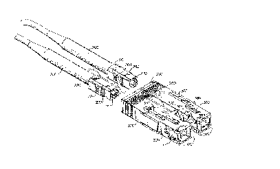
With reference to Figures 5-9, a first embodiment of the
inventive fiber opti.c connector housing 300 includes at
least two individual FOCHs 320 and 380 connected by a
single, flexible, substantially S-shaped member 350 (see, in
particular, Figures 7 and 8) extending directly from the
individual FOCH 320 to the individual FOCH 380, which
housing 300 is o~ .integral construction. The flexible member
350 serves to maintain -the individual FOCHs 320 and 380 in a
substantially side-by-side rela-tionship while permitting
each of the individual E'OCHs -to move in a-t least four
different directions relative to the other indlvidual FOCH.
EN9-92-152 ~ 1 ~ 0 ~ 7 9
These permltted movements of the individual FOCHs relative
to one another are depicted in Fi~ures lOa-lOh and
correspond to the movements depic-ted in Figure~ 2a~2h.
To limit the extent of the movements of the individual
FOCHs relative to one another , as ~Ihown, for example, in
Figure 5, the top surface of the individual FOCH 320
includes laterally projecting members 322 and 324 which
extend toward the individual FOCH 380. Similarly, as shown ,
for example, in Figures 7-9, the bottom surface of the
individual FOCH 380 includes la-terally projecting members
382 and 384 which extend toward the individual FOCH 320.
As depicted in Figure 5, the individual FOCH 320 is
capable of receiving a plug frame 220 containing a ferrule
210 which, in turn, contains the end of an optical fiber
200, e.g., a receive optical fiber, encased in one or more
plastic sheaths. Similarly, the individual FOCH 380 is
capable of receiving a plug frame 280 containing a ferrule
270 which, in turn , contains the end o~ an optical fiber
260, e.g., a transmit optical fiber, encased in one or more
plastic sheaths. The plastic sheathed optical fibers 200 and
260 are, for example, single mode fibers, and these plastic
sheathed optical fibers preferably merge into a plastic
sheathed fiber optic cable.
As shown in Figures 5-9, each of the individual FOCHs
320 and 380 is pre~erably of the so-called push-pull type
available from NTT and referred to as SC-01 straight plug
connector. However, in accordance with the invention, the
orientation of each of the individual FOCHs is rotated b~
ninety degrees relative to -the conventional orientation,
depicted in Figure 1. Consequently, each of the individual
FOCHs is still hollow and generally rectangular in
cross-section. But, in this new orientation, the height of
each of the individual FOCHs is, ~or example, 0.293 inches
(7.45 mm), while the width of each of the individual FOCHs
is, for example, 0.356 inches (9.05 mm). If the thicknesses
of the walls of the individual FOCHs is, for example, 0.0~3
inches (1.10 mm), as is conventional, and if the width of
the flexible member 350 is, for example, 0.142 inches (3.60
mm), as is also conventional, then the spaci.ng from the
center of one individual. FOC~ to the can-ter of the other
individual FOOEI, and therefore the spac~ng between the
EN9-92-152 17 2~ 79
centers of the ferrules 220 and 280 after insertion into the
individual FOCHs, is 0.5 inches (12.7 mm). Consequently, the
inventive fiber op-tic connector housiny 300 readily meets
the center-to-center spacing re~uiremen-t of the proposed
ANSI standard.
It should be noted that -the height of the flexible
member 350, i.e., the clistance from the top of the S to the
bottom of the S, is, for example, 0.106 inches (2.7 mm).
Therefore, if one were to fabricate the individual FOCHs to
have the dimensions given above, the heiyht of each of the
individual FOCHs would necessarily be greater than that of
the flexible member 350, and therefore the height of the
inventive fiber optic connector housing would necessarily be
that of the individual FOCHs, which would be 0.28g inches
(7.45 mm). In addition, the width of the inventive fiber
optic connector housing would jus-t be the sum of the widths
of the individual FOCHs and flexible member, which is just
0.856 inches (21.75 mm). Consequently, -the inventive fiber
optic connector housing 300 readily meets the height and
width requirements of the proposed ANSI standard.
With reference again to Figure 5, each of the individual
FOCHs includes conventional symmetrical, inclined surfaces
at the front end of the individual FOCH which are to be
engaged by the camming surfaces of a corresponding pair of
clips in the inventive, fiber optic receptacle, described
below. Thus, for example, the individual FOCH 320 includes
the symmetrical, inclined surfaces 32~ and 325, depicted in
~igure 5, while the individual FOCH 38Q includes the
symmetrical, inclined surfaces 3~4 and 385, also depicted in
Figure 5.
As also shown in Figure 5, each of the individual FOCHs
320 and 380 includes two opposed apertures in two opposed
walls of the individual FOCH, adjacent the corresponding,
symmetrical, inclined surfaces at the front o~ the
individual FOCH. However, ~ecause of the change in
orientation of each lndividual FOCH, these apertures are
located in opposed ver-tical sidewalls of the individual
FOCH, rather than opposed hori~ontal sidewalls of the FOCH,
as is conventional. Thus, the lndividual FOC~ 3~ includes
two opposed aper-tures 333 (shown) and 336 (no-t s:hown) in
opposed, vertical sidewalls 326 (shown) and 3~8 (not shown),
EN9-92-152 1~ 21~ ~7 ~
adjacent the symmetrical, inclined surEaces 324 and 325.
Similarly, the lndividual FOCH 380 includes two opposed
apertures 393 (not shown) and 396 (shown) in opposed,
vertical sidewalls 386 and 388, adjacent the symmetrical,
inclined surfaces 384 and 385. As is evident, and by virtue
o~ the changes in orientation of the individual FOCHs 320
and 380, the aperture 336 (not shown) of individual FOCH 320
faces the aperture 396 (shown) o.E individual FOCH 3BO.
As is conventional, the purpose of the apertures 333 and
336 in individual FOCH 320 and of apertures 393 and 396 in
individual FOCH 380 relates to the plug frames 220 and 280
containing, respectively, optical fiber 200 inserted into
ferrule 210 and optical fiber 260 inserted into ferrule 270.
That is, when plug frame 220 is inserted into individual
FOCH 320 and plug frame 280 is inserted into in~ividual FOCH
380, as depicted in Figure 6, the ferrules 210 and 270
protrude through the open ends of the individual FOCHs 320
and 380. However, the raised portions 222 (see Figure 5~ on
the sides of the plug frame 220 and the raised portions 282
(see Figure 5) on the sides of the plug frame 280 serve to
enga~e the vertical walls defining the forward ends of
apertures 333, 336, 393 and 396 if the plug frames are
p~shed too far forward within the individual FOCHs 320 and
380, preventing the plug frame~s from being inadvertently
pushed out of the individual FOCHs and preventing the
ferrules 210 and 270 from extending more than is desired
from the open ends of the individual FOCHs 320 and 380. In
addition, the raised portions 224 (see Figure 5) on the
sides of plug frame 220 and the raised portions 284 (see
Figure 53 on the sides of plug frame 280 serve to engage the
vertical walls defining the rearward ends of the apertures
333, 336, 393 and 396, preventing the plug frames 220 and
280 from being inadvertently withdra~n from the individual
FOCHs 320 and 380. Moreover, after the individual FOCHs 320
and 380 of the inventive fiber optic connec-tor horlsing 300
are inserted in-to the inventive fiber op-tic receptacle,
described below, the presence of -the apertr~res 333, 336, 393
and 396 permits the clips of the inventive fi.ber optic
receptacle to engage the plu~ frames 220 and 2~0, thereby
maintaining these plug :Erames in proper ali~nment, as
described more fully below.
EN9-92-152 19 210~79
As noted above, the inventlve fiber optic connector
housing 300 is of integral construction (and -therefore there
is no need to assemble the individual FOC~Is 320 and 380 and
flexible member 350) and is preferably entirely of plastic,
e.g., polycarbonate/acrylonitrile butadiene and styrene
blend. In addition, the inventive fiber optic connector
housing 300 is readily fabricated using conventional mold.ing
techniques, e.g., conventional injection molding techniques.
However, as also noted above, at the completion of the
molding process, to separate several parts of the
(conventional) mold from the inventive fiber optic connector
housing 300 without breaking the housing 300, it has been
found necessary to introduce notches 349 and 399 (see Figure
7) into the facing, vertical sidewalls 328 and 388 of the
individual FOCHs 320 and 380, with each notch extending
through the thickness, along the full height and partially
along the width of the corresponding sidewall. Moreover,
these notches, which have their counterpar-ts in the mold
used to form the inventive fiber optic connector housing
300, are preferably introduced into the very areas of the
sidewalls 328 and 388 containing the two facing, symmetrical
apertures 336 and 396, thereby introducing asymmetries into
the two apertures. But, as noted above, and contrary to
previous beliefs, the presence of these particular
asymmetries (more fully described below) does not result in
asymmetric forces being exerted on the individual FOCHs 320
and 380 during the insertion of the inventive fiber optic
connector housing 300 into, for example, the inventive fiber
optic receptacle, described below. As a result, the
inventive fiber optic connector housing 300 readily achieves
alignment accuracies of one micrometer or less.
With reference now to Figure 9, if each of the
individual FOCHs 320 and 380 is of the type provided by NTT
and referred to as SC-0~ straight plug connector, as is
preferred, then, as noted, the notch 349 is preferably
co-located with the aperture 336 and the no-tch 399 is
preferably co-located with the ap~rture 396. In addition, as
viewed in Figure 9, each of the notclles 349 and 399
preferably includes -three sections. The ~irst section, which
in each case is deno-ted by the let-ter A, starts at a
distance of, for example, 0.118 inches ~3.0 mm~ from the
EN9-92-152 20
0 ~7 ~
front of the corresponding individual FOCH. Significantly,
each such first section A is inclined at an angle, theta,
relative to the corresponding siclewall, which is equal -to,
for example, 22 degrees. Moreover, each such first section A
extends for a length o~, for example, 0.100 inches (2.54
mm). Each second section, which is denoted by the letter B,
runs parallel to the corresponding siclewall and extends for
a length equal to, for example, 0.089 i.nches (2.25 mm). Each
third section, which is deno-ted by the letter C, is
perpendicular to the corresponding sidewall, and extends for
a length equal to, for example, 0.0~5 inches ~1.15 mm),
which usually corresponds to the thickness of the sidewall.
As is evident from Figure 9, the notches 349 ancl 399 are
symmetrical. Moreover, as is also evident from Figure 9, if
these notches were to be combined, then the combined notches
would be substantially V-shaped in outline.
As shown, for example, in Figures 5 and 6, the
individual FOCH 320 includes a key 340 and the individual
FOCH 380 includes a key 360, which keys are intended for
insertion into corresponding keyways in the inventive fiber
optic receptacle, described below. Significantly, the key
360 is differently dimensioned from the key 340, i.e., the
width of the key 360 is less than that of the key 340. The
purpose of having differently dlmensioned keys is to ensure
that if, for example, the inventive fiher optic connector
housing 300 houses single mode fibers, that this housing 300
will only fit into a fiber optic receptacle which is to
receive such single mode fibers, i.e.,the fiber optic
receptacle will have differently dimensioned keyways,
adapted to receive the differently dimensioned keys. On the
other hand, the differently dimensioned }~eys 340 and 360 are
also intended to prevent the inventive fiber optic connector
housing 300 from fitting into a fiber optic receptacle
having, for example, equally dimensioned keyways, adapted
to receive a fiber optic connector housing con-taining, for
example, multi-mode fibers.
As also shown in, for example, Figures 5 and 6, the
individual FOCH 320 includes a spacer 342 both on -the top
and on the bottom of the individ-lal FQCH, while the
individual FOCH 3~30 includes a ~,pacer 362 bo-th on the top
and on the bottom of the individual FOCH. These spacers 3~2
E~9-92-152 21 2109479
and 362 serve to centrally positlon -the individual FOCHs in
the inventive, fiber optic receptacle, described below, when
the inventive fiber optic connector housiny 300 is inserted
into the inventive fiber op-tic receptacle.
With reference now to Fiyure 11, a second embodiment of
the inventive fiber optic connector housing 300 differs from
the first only in that this second embodiment includes two
flexible, substantially S-shaped members 350 connecting the
individual FOCHs 320 and 380. It is noteworthy that the two
flexible, substantially S-shaped members 350 are arranged
crosswise relative to one another, with the top of the S of
one member 350 corresponding to the bottom of the S of the
other member 350 and vice versa.
A preferred embodiment of the inventive, fiber optic
receptacle 400, which is adapted to receive the inventive
fiber optic connector housing 300,is depicted in Figure 12.
As shown, the receptacle 400 includes a hollow receptacle
housing 410 which, in cross-section, is generally
rectangular. The receptacle housing 410 itself includes top
and bottom walls 412 and 413, sidewalls 414 and 415 and a
rear wall 416. In addition, the receptacle housin~ 410
preferably includes a wall 418 which e~tends perpendicular}.y
from the rear wall 416 and serves to separate the rear of
the housing 410, adjacent the rear wall 416, into two
compartments 420 and 450, substan-tially of equal size. It
should be noted that at the open front end o~ the receptacle
housing 410, the top and bottom walls 412 and 413, as well
as the side walls 414 and 415, de~ine a channel 419 into
which the inventive fiber optic connector housing 300 is to
be inserted.
As shown in Fig~lre 12, the inventive fiber optic
receptacle 400 also includes a-t least a first pair of clips
430, and preferably also a second pair of clips 460, which
extend perpendicularly from the rear wall 416 into the
compartments 420 and 450. To conform to the orientation of
the apertures in the side wa]ls of the individual FOCHs of
the inventive fiber optic connector housing 300, the
orientations of the two pairs of clips 430 and 460 have been
rotated by ninety degrees relative to the orientations of
the clips depicted in Fi.gure 1. In addition, the pair of
clips 430 includes symmetrical cammlng surfaces ~32, and the
EN9-92-152 22 210~
pair of clips 460 includes symmetrical camming surfaces 462,
adapted to engage the symmetr.ical, inclined surfaces and
(as~mmetrical) apertures of the individual E'OCHs of the
inventive ~iber optic connector housing 300.
As also shown in Figure 12, the rear wall 416 includes
an aperture 440, centrally located between clips 430, and an
aperture 470, centrally located between clips 460, which
apertures are intended to receive the two bores of an
electro-optic module.
Signi~icantly, as noted above, the fiber optic
receptacle housing 410 and the two pairs of clips 430 and
450 are of integral construction. Conse~uently, there is no
need to assemble this housing and these clips. In addition,
the inventive fiber optic receptacle 400 is readily
dimensioned to receive the lnventive fiber optic connector
housing 300, when dimensioned in accordance with the
proposed ANSI standard, thereby also conforming to this
proposed standard.
The inventive fiber optic receptacle 400 is preferably
fabricated using conventional molding techniques, e.g.,
conventional injection molding techniques. Moreover, the
~iber optic receptacle housing 41t) and two pairs of clips
430 and 460 are preferably entirely of plastic, e.g.,
polycarbonate/acrylonitrile butadiene and styrene blend.
As noted above, at the completion of the molding process
used to fabricate the inventive fiber optic receptacle 400,
to separate several parts of the corresponding
(conventional) mold from the flber optic receptacle 400
~ithout breaking the receptacle 400, it has been found
necessary to introduce openings into the walls of the
receptacle housing 410. That is, as shown in Figure 12, it
has been found necessary to introduce identical openings 425
(not shown~ and 426 (shown) into the bottom and top walls
413 and 412, directly below and above the compartment 420,
containing the pair of clips 430. In addition, it has been
found necessary to introduce identical openings 455 (not
shown) and 456 tshown) into the bottom and top walls 413 and
412, directly below and above the compar-t!ment 450,
containing the pair of clips 460. As depict:ed, these
openings 425, 426, 455 and ~56 are preferab.~y rectaIlgular in
outline. In addition, these openin~s, which have their
EN9 - g 2 - 1 5 2 2 3 ~ 9
counterpar-ts in the mold used to fabricate the inventive
f.iber optic receptacle 400, extend longitudinally from the
rear end of the receptacle housing 410, where the two bores
of an electro-optic module are to be received, toward the
front end of the receptacle housing 410, where the inventive
fiber optic connector ~ousing 300 is to be received.
Moreover, the longitudinal extent of these openings is
greater than that of the two pairs of clips 430 and ~60.
As shown in Figure 13, the top wall 412 of the
receptacle housing 410 includes differently dimensioned
keyways 435 and 465 adapted to receive the differently
dimensioned keys 340 and 360 on the individual FOCHs 320 and
380 of the inventive fiber optic connector housing 300.
Obviously, because the longitudinal extent of the openings
426 and 456 in the top wall 412 is greater than that of the
two pairs of clips 430 and 460, it follows that the keyways
435 and 465 do not extend all the way to the two pairs of
clips. However, in accordance with the invention, the
longitudinal spacing between the front end of each pair of
clips 430 and ~60 and the corresponding keyway is preferably
no greater than the longitudinal extent of the front end of
the individual FOCH to be engaged by the pair of clips,
containing the symmetrical, inclined surfaces to be engaged
by the symmetrical camming surfaces of the clips. Provided
this longitudinal spacing requirement is met, the keyways
435 and 465 are effective ln properly aligning the
individual FOCHs relative to the bores to be inserted at the
rear end of the inventive fiber optic receptacle 400, and in
enabling the corresponding transmit and receive optical
fibers to achieve micrometer-accurate alignment. By way of
example, the longitudinal extent of the front end of each of
the individual FOCHs 320 and 380 depicted in Figure 9,
including just the corresponding inclined surfaces 324/325
and 384/385 is, for example, 0.055 inches (1.39 mm).
Therefore, provided the longitudinal spacing between the
keyway 435 and the pair of clips 430, as well as the
longitudinal spacing between th0 keyway 465 and the pair of
clips 460, is, for examp:le, 0.038 inches (0.g6 mm), -the
keyways 435 and 465 will be effectiv0 in properly aligning
the individual FOCHs 3~0 and 380 of -the inventive fiber
optic connector housing 300 relative -to the bores to be
EN9-92-152 24
4 7 9
inserted at the rear end of -the inventive fiber optic
receptacle 400.
With reference to Figures 14 and 15, the left-hand
portion (as viewed in Figures 14 and 15) of the channel 419
of the inventive fiber optic receptacle 400, which is
aligned with the compartment 420, co~tains a first shutter
490, which is pivotably connected to the bottom wall 413 of
the receptacle housing 410, and a second shutter 510, which
is positioned behind the first shutter 490 and is pivotably
connected to the top wall 412 of the receptacle housing 410.
These two shutters are intended to prevent any light which
might emanate from the bore of a TOSA received in
compartment 420 from reaching human eyes when there is no
fiber optic cable in the channel 419.
As shown in Figures 14 and 15, the shutter 490 extends
upwardly into the channel 419 through an aperture in the
bottom wall 413 of of the fiber optic receptacle housing
410. As also shown, the bottom of the shutter 490 includes
two cylindrical arms 492 and 494 which contact the bottom of
the wall 413. These cylindrical arms 492 and 494 are
encircled by a helical spring 496 which serves to bias the
shutter 490 to the vertical position shown in Figure 15,
where the shutter 490 serves to block light. By pushing
inwardly on the shutter 490, this shutter is readily pivoted
to a substantially horizontal position, where it serves to
block relatively little light.
The sh~tter 510 extencls downwardly into the channel 419
through an aperture in the top wall 412 of the fiber optic
receptacle housing 410. As shown, the top of the shutter 510
includes two cylindrical arms 512 and 514 which contact the
top of the wall 412. These cylindrical arms are encircled by
a helical spring 516 which serves to bias the shutter 510 to
the vertical position shown in Figure 15, where the shutter
5~0 serves to block light. By pushing inwardly on the
shutter 510, this shutter is also readily pivoted to a
substantially horizontal position, where it serves to block
relatively light.
Significantly, as shown in Figures 14 and 15, the body
of the shutter 490 includes two interconnected portions 497
and 498. The first portion 497 is substantially rectangular
and includes a central, substantially rectangular cutout. I-t
EN9-92-152 25 ~ 7 9
is this first portion 497 which is adapted -to be engaged by
an individual FOC~ inserted into -the channel 419 and/or by a
plug frame contained in the individual FOCH. The second
portion 498 is generally L-shaped, is positioned directly
behind the cutout in the firs-t portion 497 and is connected
to the first portion by the bottom of the L. This second
portion, like the first portion, is adapted to block light
when the shutter 490 is in the vertical position. However,
this second portion is positioned so as to be aligned with a
ferrule contained in the above-mentioned plug frame. But,
because the second portion 498 is positioned behind the
first portion 497, at a sufficient distance to avoid contact
with the ferrule, there is no contact between the ferrule
and the first shutter 490 when the individual FOCH is
inserted into the channel 419, which might otherwise cause
damage to the ferrule.
As with the body of the firs-t shutter 490, the body of
the second shutter 510 also includes two interconnected
portions 517 and 518, having similar configurations -to those
of the interconnected portions 497 and 498 of the first
shutter 490, for the reasons given above.
The manner in which the inventive fiber optic connector
housing 300 is inserted into -the inventive fi~er optic
receptacle 400, and the manner in which the latter serves to
align the former relative to the bores of an electro-optic
module, are depicted in Figures 16(a)-16(b). On the other
hand, the manner in which t~e former is withdrawn from the
latter is depicted in Figures 16(c)-16(d). I-t should be
noted that ~he mechanical interactions betweell the
symmetrical, inclined surfaces of the individual FOCHs and
the camming surfaces of the clips is as described above.
The purpose of the inventive fiber optic connector
housing 3Q0 and inventive fiber optic receptacle 400 is, of
couse, to align the optical fibers 200 and 260 (see Figures
5 and 6) ~ith corresponding bores of a TOSA and ROSA of an
optoelectronic module, thereby formi.ng an optical assembly.
Just such an op-tical assembly 140Q is depicted in Figure 17.
As shown, the optical assembly 1400 comprises an
optoelectronic module 1300, whic:h lncludes a housing ~200,
consisting of lower and upper halves lO00 and 1100,
containing a substrate g00, e.g., a circuitized, pinned,
. .~ -. , .
EN9-92-152 26
2~0~79
ceramic substrate, bearing TOSA and ROSA ICs. The
optoelectronic module 1300 also includes a housing 800 which
is connected to the housing 1200, and includes apertures 810
and 820. The optoelectronic module 1300 further includes a
TOSA 600 which fits into the aperture 810 and is
electrically connected to the TOSA ICs on the substrate 900.
Moreover, the optoelectronic module 1300 ~till further
includes a ROSA 700 which fits into the aperture 820 and is
electrically connected to the ROSA ICs on the substrate 900.
The optical assembly 1400 also includes the inventive
fiber optic receptacle 400 which is connected to the housing
800. Such connection is achieved by inserting the ears 522
and 524 of the receptacle 400 into corresponding slots ~30
and 850 in the housing 800. As shown, an aperture 840
extends through the slot 830, which is aligned with the
aperture 523 in the ear 522 of the receptacle 400.
Similarly, an aperture 860 extends through the slot 850,
which is aligned with the aperture 525 in the ear 524 of the
receptacle 400. Thus, by inserting a pin 872 through aligned
apertures ~40 and 523, and by inserting a pin 874 through
aligned apertures 860 and 525, the receptacle 400 is readily
connected to the housing 800. As a consequence, the bores of
the TOSA 600 and ROSA 700 extend into the compartments 4~0
and 450 at the rear of the receptacle 400.
Finally, as shown in Figure 17, the optical assembly
1400 also includes the inventive fiber optic connector
housing 300 containing two plug frames, each of which
contains an optical fiber-con-taining ferrule. The houslng
400 and its optical fiber containing ferrules become a part
of the optical assembly 1400 by inserting the housing 300
into the receptacle 400, thereby automatically aligning the
optical fibers contained in the housing 300 with the bores
of the TOSA and ROSA 600 and 700.
Significantly, the invention also involves a number of
accessory devices which have been developed for use in
connection with electro-optic modules. The accessory devices
developed to date include two devices for cleaning the
lenses in the bores of optical subassemblies, a device
(often called a wrap plug) for communicating the light
produced by a TOSA o.f an electro-optic module to the ROSA of
the same electro-optic module, as well as a shipping~storage
EN9-92-152 27 2 ~ 79
plug for one or more op-tlcal .subas~emblies of an
electro-optic module. All of these devices are related in
the sense that each includes components which fit into one
or more plug frames adapted to receive the components, and
each plug frame fits into an unmodified, individual FOCH. I~
the device involves the use of two plug frames, then the two
plug frames are preferably inserted into the inventive fiber
optic connector housing 300.
The first of the accessory devices, which is useful for
cleaning the surface of a lens in a bore of an electro-optic
module with a fluid, such as air, is depicted in Figure 18
and is denoted by the number 1500. As shown, the device 1500
includes a hollow tube 1510 into which the cleaning fluid is
to be injected. The device 1500 also includes a hollow,
tubular nozzle 1520, through which the cleaning fluid is to
be ejected, with the front end of the hollow tube 1510
fltting into the rear end of the nozzle 1520.
Significantly, as shown in Figure 1~, the device 1500
further includes an essentially conventional plug frame 1530
into which the nozzle 1520 and hollow tube 1510 are to be
inserted, with the front of the nozzle 1520 protruding from
the plug frame and the rear of the tube 1510 protruding from
the rear of the plug frame. In this regard, it should be
noted that the top of the plug frame has been removed to
permit ready insertion of the nozzle 1520 and hollow tube
1510. Moreover, the body of the plug frame 1530 includes
internal, aligned notches 1532 and 1534 into which a keeper
1540 is to be inserted, after the nozzle 1520 and hollow
tube 1510 have been inserted into the plug frame 1530, for
the purpose of keeping the nozzle and hollow tube in place.
Because the plug frame 1530 is essentially conventional,
it is readily inserted into a conventional individual FOCH.
By inserting the individual FOCH in-to a ~iber optic
receptacle connected to an elec-tro-optic modul~, the lens in
a bore of the module is readily cl0aned with a fluid, such
as air, simply by connecting a source of the fluid to the
rear of the hollow tube 1510, and flowing -the fluld into the
hollGw tube 1510 under pressure. This pressurized fluid will
be ejected from the nozzle to impinge upon the surface of
the lens to be c].eaned.
., ,~
EN9-92-152 2~ 21~0~79
If two plug frames, containing two nozzles and two
hollow tubes, are to be used, then the two plug frames are
preferably inserted into the inventive fiber optic connector
housing 300, pictured in Figure 18.
The second of the accessory devices, which is useful for
brushing or wiping dirt from the surface of a lens in a bore
of an electro-optic module, is depicted in Figure 19 and is
denoted by the number 1600. As shown, the device 1600
includes a hollow or solid rod 1610 which can, for example,
be identical to the hollow tube 1510 shown in Figure 18. In
addition, the device 1600 includes a brush rod 1620, the
front of which contains a brush-like member 1621 for
brushing or wiping dirt from the surface of a lens, with the
front end of the rod 1610 fitting into the rear of the brush
rod 1620. Moreover, the device 1600 further includes a
helical spring 1625 which encircles the brush rod 1620, with
the rear end of the spring 1625 abutting an external
shoulder 1615 of the rod 1610.
As before, the device 1600 also includes an essentially
conventional plug frame 1630, which is identical to the plug
frame 1530 pictured in Figure 18. It should be noted that
the plug frame 1630 (like the identical plug frame 1530)
includes an internal shoulder 1631 and internal, aligned
notches 1632 and 1634 adapted to receive a keeper 1640.
Because the top of the plug frame 1630 has been removed,
the brush rod 1620, encircled by the helical spring 1625,
and the rod 1610, are readily inser-ted into the plug frame
1630. Once so inserted, the front of the helical spring
abuts the internal shoulder 1631 of the plug frame 1630,
while the rear of the helical spring abuts the external
shoulder 1615 of the rod 1610. III addition, once the brush
rod 1620, helical spring 1625 and rod 1610 are inserted into
~the plug frame, the keeper 1640 is inserted illtO the
internal notches 1632 and 1634 for the purpose of keeping
the brush rod 1620, helical spring 1625 and rod 1610 in
place.
To brush or wipe the surface of a 1.ens in a bore of an
electro~optic module, one merely i.nserts the plug frame 1630
into a conventional individual FOCH, and inserts the
individual FOCH into a fiber optic receptacle connected to
the electro-optic module of interest. By pushing on the end
EN9-92-152 29 21~79
of the (spring-loaded) rod 1610, the surface of the lens in
the bore is brushed or wiped by the brush-like member 1621
on the end of the brush rod 1620.
If two plug frames 1630 are to be used, then the two
plug frames arP preferably inserted into the inventive fiber
optic connector housiny 300, pictured :in Figure 19.
The third of the accessory devic:es, which is a wrap
plug, is depicted in Figure 20 and is deno-ted by the number
1700. As shown, the wrap plug 1700 inc:Ludes an optical fiber
1710, e.g., a single mode fiber or a multi-mode fiber, with
the opposite ends of the optical fiber 1710 being inserted
into ferrules 1716 and 1718. A first helical spring 1712
encircles the optical fiber adjacent the ferrule 1716, and
abuts an external shoulder of the . ferrule 1716. In
addition, a second helical spring 1714 encircl~s the optical
fiber 1710 adjacent the ferrule 1718, and abuts an external
shoulder of the ferrule 1718.
Significantly, the wrap plug 1700 also includes two
essentially conventional plug frames 1730, which are
identical to the plug frames 1630 and 1530 pictured in
Figures 19 and 1~. Each of these plug frames 1730 includes
an internal shoulder 1731 and internal, aligned notches 1732
and 1734 which are adapted to receive a keeper 1740.
In use, the optical fiber 1710 is inserted into both of
the plug frames 1730, with a first portion of the optical
fiber 1710 being contained in one of the plug frames 1730, a
second portion being contained in another o~ the plug frames
1730 and a third portion extending between the plug frames.
In addition, the optical fiber 1710 is positioned so that
the ferrule 1716 protrudes from -the front of one of the plug
frames 1730 and the rear of -the helical spring 1712 abuts
the internal shoulder 1731 of the corresponding plug frame.
Moreover, the optical fiber 1710 is positioned so that the
~errule 1718 protrudes from the front of the other plug
frame 1730 and the rear of -the helical spring 1714 also
abuts the internal shoulder 1731 of the corresponding plug
frame. Further, the keepers 1740 are inserted into the
internal notches 1732 and 1734 in the two plug fra~es in
order to keep the optical fiber 1710, the helical springs
1712 and 1714, and ferrules 1716 and 171~ in place.
EN9-92-152 30 ~ a 47 ~
Because the wrap plug 1700 necessarily includes two plug
frames 1730, these plug frames are preferably inserted into
the inventive fiber optic connector housing 300 . Thus, when
the light emitted by a TOS~ of an electro-optic module is to
be communicated to the ROSA of the same module then, in
accordance with the invention, -the inventive fiber optic
connector housing 300, containing the two plug frames 1730
and optical fiber 1710, is inserted into, for example, the
inventive fiber optic receptacle 400, which is connected to
the electro-optic module.
The fourth of the accessory devices, which is a
shipping/storage plug for a TOSA or a ROSA of an
electro-optic module, is depicted in Figure 21 and is
denoted by the number 1800. As shown, the shipping/storage
plug 1800 includes a nipple 1810 which is to be inserted
into the front of an e~sentially conventional plug frame
1830, which is identical to the plug frames 1730, 1630 and
1530, discussed above. The nipple 1810 is maintained in the
plug frame 1830 by inserting a keeper 1840 into the
internal, aligned notches 1832 and 1834 of the plug frame
1830.
In use, the plug frame 1830, containing the nipple 1810,
is inserted into a conventional individual FOCH, which is
inserted into a fiber optic receptacle connected to the
electro-optic module of interest.
If two plug frames 1830, con-taining two nipples 1810,
are required, then the two plug frames 1830 are preferably
inserted into the inventive fiber optic connector housing
300, pictured in Figure 21.
While the invention has been particularly shown and
described with reference to preferred embodiments thereof,
it will be understood by those skilled in the art that
various changes in form and details may be made therein
without departing from the spirit and scope of the
invention.