Language selection

Search

Patent 2100684 Summary

Third-party information liability

Some of the information on this Web page has been provided by external sources. The Government of Canada is not responsible for the accuracy, reliability or currency of the information supplied by external sources. Users wishing to rely upon this information should consult directly with the source of the information. Content provided by external sources is not subject to official languages, privacy and accessibility requirements.

Claims and Abstract availability

Any discrepancies in the text and image of the Claims and Abstract are due to differing posting times. Text of the Claims and Abstract are posted:

  • At the time the application is open to public inspection;
  • At the time of issue of the patent (grant).
(12) Patent: (11) CA 2100684
(54) English Title: ELECTRO-PNEUMATIC SPRING AND SERVICE BRAKE ACTUATOR
(54) French Title: COMMANDE DE FREIN ELECTRO-PNEUMATIQUE
Status: Expired and beyond the Period of Reversal
Bibliographic Data
(51) International Patent Classification (IPC):
  • B60T 13/26 (2006.01)
  • B60T 13/66 (2006.01)
  • B60T 17/08 (2006.01)
(72) Inventors :
  • LATVALA, BRUCE EARL (United States of America)
(73) Owners :
  • BENDIX COMMERCIAL VEHICLE SYSTEMS, LLC
  • ALLIED-SIGNAL INC.
(71) Applicants :
  • BENDIX COMMERCIAL VEHICLE SYSTEMS, LLC (United States of America)
  • ALLIED-SIGNAL INC. (United States of America)
(74) Agent: MACRAE & CO.
(74) Associate agent:
(45) Issued: 2001-09-04
(86) PCT Filing Date: 1991-06-13
(87) Open to Public Inspection: 1992-08-06
Examination requested: 1998-04-17
Availability of licence: N/A
Dedicated to the Public: N/A
(25) Language of filing: English

Patent Cooperation Treaty (PCT): Yes
(86) PCT Filing Number: PCT/US1991/004229
(87) International Publication Number: WO 1992012879
(85) National Entry: 1993-07-15

(30) Application Priority Data:
Application No. Country/Territory Date
647,316 (United States of America) 1991-01-29

Abstracts

English Abstract


An electro-pneumatic braking system includes a tandem brake actuator (12)
including a service brake actuating section (16)
and an emergency/parking spring actuated section (18). Hold-off pressure is
communicated to the emergency/parking section
through a three-way solenoid valve (54) from a pressure reservoir (42), and
communication to the service actuator is controlled by
electro-pneumatic modulator (56). Service pressure is taken both from the
branch of the conduit communicating with the air reser-
voir (42), but also from the hold-off pressure in the emergency/parking
reservoir (34). Accordingly, only a single line communi-
cates fluid pressure from the reservoir to the brake, and service brake
response; time is improved because the hold-off pressure
and the emergency/parking section of the actuator is used as a small reservoir
immediately adjacent the service actuator.


Claims

Note: Claims are shown in the official language in which they were submitted.

-7-
Claims
1. Fluid pressure braking system comprising a
fluid pressure source (42) and a tandem brake actuator (12)
including a housing (14) having a service actuating section
(16) and a spring actuating section (18), said service
actuating section (16) including fluid pressure responsive
means (24,26) for effecting a service brake application,
said spring actuating section (18) including a pressure
responsive member (32) cooperating with said housing (14) to
define a pressure chamber (34) and a spring actuator (38)
acting through the pressure responsive member (32) for
effecting a spring brake application, said pressure
responsive member (32) being responsive to fluid pressure in
said pressure chamber (34) above a predetermined level to
disable said spring actuator (38) to thereby effect spring
brake release, said pressure responsive member (32) being
responsive to fluid pressure in the pressure, chamber (34)
below a predetermined level to permit said spring actuator
(38) to effect a spring brake application, characterized in
that said system includes means for transferring
(46,48,54,56) fluid pressure from said pressure chamber (34)
to said fluid pressure responsive means (24,26) when a
service brake application is effected to operate said fluid
pressure responsive means (24,26) to effect a service brake
application.
2. Fluid pressure braking system as claimed in
Claim 1, further characterized in that conduit means (44)
communicate said pressure source (42) with said tandem brake
actuator (12), said means for transferring (46,48,54,56)
including a first branch (46) of said conduit means (44)
communicating with the pressure chamber (34) and a second
branch (48) of said conduit means (44) communicating with
the fluid pressure responsive means (24,26) and with said
first branch (46) whereby fluid pressure is transferred from
said pressure chamber (34) to said fluid pressure responsive
means (24,26) through said first and second branches (46,48)
during a service brake actuation.

3. Fluid pressure braking system as claimed in
Claim 2, further characterized in that said first branch
(46) includes operator actuated valve means (54) shiftable
from a first condition venting said pressure chamber (34)
and closing off communication through said first branch (46)
to said pressure source (42) to thereby effect a spring
brake actuation to a second condition communicating the
pressure chamber (34) with the pressure source (42) to
effect spring brake release.
4. Fluid pressure braking system as claimed in
Claim 3, further characterized in that said second branch
(48) includes valve mechanism (58) controlling communication
through said second branch (48) to said pressure responsive
means (24,26) to thereby effect a service brake application.
5. Fluid pressure braking system as claimed in
Claim 4, further characterized in that both said valve means
(54) and said valve mechanism (58) are electrically
actuated.
6. Fluid pressure braking system as claimed in
Claim 4, further characterized in that said conduit means
(44) includes a third branch (52) communicating both of said
first and second branches (46,48) to said pressure source
(42), said second branch (48) communicating said pressure
responsive means (24,26) with both said pressure source (42)
through said second and third branches (48,52) and with said
pressure chamber (34) through said second and first branches
(48,46) when a service brake actuation is effected.
7. Fluid pressure braking system as claimed in
Claim 2, further characterized in that said conduit means
(44) includes a third branch (52) communicating both of said
first and second branches (46,48) to said pressure source
(42), said second branch (48) communicating said pressure
responsive means (24,26) with both said pressure source (42)
through said second and third branches (48,52) and with said
pressure chamber (34) through said second and first branches
(48,46) when a service brake actuation is effected.

Description

Note: Descriptions are shown in the official language in which they were submitted.


~,10~3~84
- 1 -
ELECTRO-PNEUMATIC SPRING AND
SERVICE BRAKE ACTUATOR
This invention relates to a tandem spring and
service brake actuator for an electro-pneumatic braking
system.
Conventional pneumatic braking systems for heavy
duty vehicles use tandem brake actuators to effect actuation
of the vehicle foundation brake. These tandem brake
actuators include a service brake actuator, which is
responsive to fluid pressure to effect a service brake
application, and also include a spring brake actuator to
effect an emergency and/or parking brake application. The
spring actuator includes a heavy duty spring which yieldably
urges the actuator rod in a brake application effecting
direction. The spring is apposed by pneumatic "hold off"
pressure during normal operation of the vehicle to permit a
service brake application t:o be effected in the normal way.
However, the hold-off pressure is vented during emergency
conditions or when the vehicle is parked, to permit the
spring to effect an emergency or parking brake application.
Both the service braking pressure and the hold-off braking
pressure are controlled by pneumatic signals generated by
the vehicle operator. In such conventional systems, both
the service brake pressure and the hold-off pressure are
routed to the tandem actuator through separate brake lines.
Such a prior art system is disclosed in GB-A-2 193 772.
More recently, it has been proposed to replace the
conventional pneumatic braking control system with an
electro-pneumatic system in which electrical signals are
generated by the vehicle operator to effect control of both
the vehicle service and parking/emergency braking systems.
Such a system is disclosed in U.S. Patent 4,749,238.
The present invention minimizes the pneumatic
lines and fittings used in an electro-pneumatic braking
system to
~'. 92,~ SUBSTITUT~ So-I~~T

WO 92/12879 ~, ~ ~ ~ ~ PCT/US91 /04229
- 2 -
of the invention is that the hold-off pressure used to
hold off the spring brake is used to supplement the
pressure communicated from the reservoir to the service
brake when a service brake application is effected.
05 accordingly, only one pneumatic line need be routed to
each actuator, and this line may be smaller than would
otherwise be necessary because the spring hold-off
pressure is used to assist in effecting a service brake
application. The amount of hold-off pressure used during
a normal brake application, which usually is a relatively
low pressure application, will not normally decrease the
hold-off pressure below that required to prevent the
spring from cycling. Accordingly, the impact on spring
life is minimal. If desired, during high-force
applications, service brake actuation time can be further
reduced by allowing the spring to supplement the service
actuator during the initial application to momentarily
compound the load from the two actuators. This would also
decrease the required capacity of the supply line from the
reservoir.
These and other advantages of the present
invention will become apparent from the following
description, with reference to the accompanying drawing,
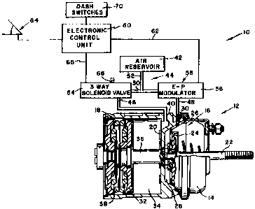
the sole Figure of which is a schematic illustration of a
braking system made pursuant to the teachings of the
present invention.
Referring now to the drawing, an electro-
pneumatic brake actuation system generally indicated by
the numeral 10 includes a tandem actuator generally
indicated by the numeral 12. The actuator 12 includes a
housing 14 which is divided by a dividing wall 20 into a
service actuating section 16 and a parking/emergency
spring actuating section generally indicated by the
numeral 18. The service actuator section 16 includes an
actuating rod 22 which extends out of the housing 14 and
which is connected to a conventional vehicle service brake
(not shown) in a manner well known to those skilled in the
art. The rod 22 extends from a pressure plate 24 which is

WO 92/12879 ~ ~ ~ ~ ~ PCT/US91/04229
- 3 -
connected to the wall of the housing 14 by a diaphragm 26
to thereby form a fluid pressure receiving compartment 28
between the diaphragm 26 and the wall 20. An inlet
opening 30 is provided for communicating fluid pressure
05 into the compartment 28.
The spring actuating section 18 includes a
pressure responsive member 32 which cooperates with the
wall of the housing 14 and the wall 20 to define a
pressure chamber 34. The pressure responsive member 32
includes a stem 36 which extends through an opening in the
wall 20 to engage the pressure plate 24. The pressure
responsive member 32 is yieldably urged to the right,
viewing the Figure, by a heavy actuation spring 38.
Accordingly, when the pressure chamber 34 is vented, the
spring 38 urges the pressure responsive member 32 and the
actuating rod 22 to the right, viewing the Figure, thereby
effecting an emergency/parking brake application.
However, when hold-off pressure is communicated into the
pressure chamber 34, the pressure responsive member 32 is
urged to the position illustrated, thereby compressing the
spring 38. An inlet 40 communicates hold-off pressure
into the pressure chamber 34.
Fluid pressure is communicated to the ports 30
and 40 from a source of fluid pressure, such as a
compressed air reservoir 42, by a conduit generally
indicated by the numeral 44. Conduit 44 includes a first
branch 46 which communicates with the inlet port 40, a
second branch 48 which communicates with compartment 28
and with the first branch 46 through three-way junction
50, and a third branch 52 which communicates the junction
50 to the air reservoir 42. A three-way solenoid valve 54
controls communication through the branch 46, and an
electro-pneumatic modulatar 56 controls communication
through the branch 48. Although illustrated separate from
the tandem action 12 for clarity, it is within the scope
of the invention to mount a solenoid valve 54 and the
electro-pneumatic modulator 56 directly upon the housing
14, so that the branches 46 and 48 may be made extremely

CA 02100684 2001-O1-31
-4-
short. Accordingly, fluid pressure is communicated from the reservoir 42
through the third
branch 52 alone, instead of the two separate air lines required in prior art
actuators.
The electro-pneumatic modulator 56 may be of the proportional type or a relay
valve
having separate electrically operated solenoids which respectively control
communications
between the modulator and exhaust opening 58 and between the modulator and the
second
branch 48. Such a modulator is the same general type shown in U.S. Patent
3,747,992. In
either case, the modulator 56 responds to electrical signals generated by an
electronic control
unit 60 and transmitted to the modulator over lead 62 to establish a pressure
level in
compartment 28 that is a direct function of, and proportional to, the signals
generated by a foot
operated brake treadle generally indicated by numeral 64. The treadle 64 is
operated by the
vehicle operator, and generates an electrical signal which varies in
accordance with the
magnitude of braking demanded by the vehicle operator. This signal is
transmitted to the
electronic controller 60, which processes the signal and generates the signals
which actuate the
electro-pneumatic modulator 56.
Three-way solenoid valve 54 is conventional, and in its normal or deenergized
state
closes off communication between the junction 50 and inlet 40 and vents inlet
40 to atmosphere
through atmospheric vent 66. When the solenoid valve 54 is energized, the vent
66 is closed,
and communication is permitted from the junction 50 to the inlet port 40,
thereby supplying
hold-off pressure into the pressure chamber 34. Three-way solenoid valve 54 is
also controlled
by the electronic control unit 60 through electrical signals transmitted
thereto through lead 68.
The electric control unit 60 is caused to generate signals actuated three-way
solenoid valve 54
by dash switches 70 which are operated by the vehicle

WO 92/12879 PCT/US91/04229
- 5 ~~
operator. The dash switches 70, are more completely
disclosed in U.S. patent 4,763,959.
In operation, when the vehicle is to be moved,
the dash switches 70 are operated, causing the electronic
05 control unit 60 to energize three-way solenoid valve 54 to
communicate fluid pressure from reservoir 42 into the
pressure chamber 34. Pressure in chamber 34 overcomes the
force of the spring 38, compressing the latter into the
position illustrated in the drawing, thus releasing the
emergency/parking brake application effected by the spring
38 to permit the vehicle to be moved. During vehicle
operation, a service brake actuation is effected by
operation of the treadle 64. This causes the
electro-pneumatic modulator 56 to establish a pressure
level in compartment 28 which is a function of the degree
which the treadle 64 has been depressed. Accordingly, the
actuating rod 22 and pressure plate 24 are urged to the
right. viewing the Figure, while the pressure responsive
member 32 remains in the released position illustrated in
the drawing due to the maintenance of hold-off pressure in
chamber 34.
Upon the operation of modulator 56 to communicate
fluid pressure into the compartment 28, fluid pressure is
taken from the common junction 50 between the third branch
52 of conduit 44 communicating with the reservoir 42 and
from the first branch 46 of conduit 44 communicating with
pressure chamber 34, because the three-way solenoid valve
has been opened to permit movement of the vehicle.
Accordingly, the line or branch 52 may be made smaller
than would otherwise be necessary, because the pressure
chamber 34 acts as a relatively small reservoir
immediately adjacent the service actuator 16. Normal
service actuations are of relatively low pressure, so that
the pressure level in pressure chamber 34 is maintained at
a sufficiently high level to maintain compression of
spring 38. Accordingly, the spring 38 will not be cycled
during normal service actuatians of the actuator 12, so
that life of the spring 38 will not be affected. However,

WO 92/ 12879 ~~ ~ ~ ~ ~ L~ PCT/US91 /04229
- 6 -
in case of a high pressure emergency service actuation, it
is within the scope of the invention that the electronic
control unit 60, when a service brake of relatively high
pressure is demanded, causes deactuation of the solenoid
05 valve 54, so that the pressure level in pressure chamber
34 is also depleted by venting to the atmosphere, causing
the spring 38 to make a momentarily compounded brake
application to supplement the actuation generated by the
pressure level in compartment 28. Accordingly, the size
of the conduit branch 52 can even be further reduced from
that that would be otherwise necessary.
20
30

Representative Drawing
A single figure which represents the drawing illustrating the invention.
Administrative Status

2024-08-01:As part of the Next Generation Patents (NGP) transition, the Canadian Patents Database (CPD) now contains a more detailed Event History, which replicates the Event Log of our new back-office solution.

Please note that "Inactive:" events refers to events no longer in use in our new back-office solution.

For a clearer understanding of the status of the application/patent presented on this page, the site Disclaimer , as well as the definitions for Patent , Event History , Maintenance Fee  and Payment History  should be consulted.

Event History

Description Date
Time Limit for Reversal Expired 2006-06-13
Letter Sent 2005-06-13
Inactive: Late MF processed 2003-07-21
Letter Sent 2003-06-13
Letter Sent 2002-07-29
Grant by Issuance 2001-09-04
Inactive: Cover page published 2001-09-03
Inactive: Final fee received 2001-05-31
Pre-grant 2001-05-31
Inactive: Office letter 2001-05-30
Inactive: Multiple transfers 2001-04-20
Letter Sent 2001-03-19
Notice of Allowance is Issued 2001-03-19
Inactive: Approved for allowance (AFA) 2001-03-06
Amendment Received - Voluntary Amendment 2001-01-31
Inactive: S.30(2) Rules - Examiner requisition 2000-09-14
Inactive: Application prosecuted on TS as of Log entry date 1998-06-17
Inactive: RFE acknowledged - Prior art enquiry 1998-06-17
Inactive: Status info is complete as of Log entry date 1998-06-17
All Requirements for Examination Determined Compliant 1998-04-17
Request for Examination Requirements Determined Compliant 1998-04-17
Application Published (Open to Public Inspection) 1992-08-06

Abandonment History

There is no abandonment history.

Maintenance Fee

The last payment was received on 2001-03-29

Note : If the full payment has not been received on or before the date indicated, a further fee may be required which may be one of the following

  • the reinstatement fee;
  • the late payment fee; or
  • additional fee to reverse deemed expiry.

Please refer to the CIPO Patent Fees web page to see all current fee amounts.

Fee History

Fee Type Anniversary Year Due Date Paid Date
MF (application, 7th anniv.) - standard 07 1998-06-15 1998-03-24
Request for examination - standard 1998-04-17
MF (application, 8th anniv.) - standard 08 1999-06-14 1999-03-26
MF (application, 9th anniv.) - standard 09 2000-06-13 2000-03-27
MF (application, 10th anniv.) - standard 10 2001-06-13 2001-03-29
Registration of a document 2001-04-20
Final fee - standard 2001-05-31
Registration of a document 2002-05-06
MF (patent, 11th anniv.) - standard 2002-06-13 2002-05-31
Reversal of deemed expiry 2003-06-13 2003-07-21
MF (patent, 12th anniv.) - standard 2003-06-13 2003-07-21
MF (patent, 13th anniv.) - standard 2004-06-14 2004-05-25
Owners on Record

Note: Records showing the ownership history in alphabetical order.

Current Owners on Record
BENDIX COMMERCIAL VEHICLE SYSTEMS, LLC
ALLIED-SIGNAL INC.
Past Owners on Record
BRUCE EARL LATVALA
Past Owners that do not appear in the "Owners on Record" listing will appear in other documentation within the application.
Documents

To view selected files, please enter reCAPTCHA code :


To view images, click a link in the Document Description column. To download the documents, select one or more checkboxes in the first column and then click the "Download Selected in PDF format (Zip Archive)" or the "Download Selected as Single PDF" button.

List of published and non-published patent-specific documents on the CPD .

If you have any difficulty accessing content, you can call the Client Service Centre at 1-866-997-1936 or send them an e-mail at CIPO Client Service Centre.


Document
Description 
Date
(yyyy-mm-dd) 
Number of pages   Size of Image (KB) 
Description 2001-01-31 6 266
Cover Page 2001-08-21 1 47
Cover Page 1994-03-19 1 25
Description 1994-03-19 6 329
Description 1998-08-11 6 270
Representative drawing 2001-08-21 1 14
Claims 1994-03-19 2 126
Drawings 1994-03-19 1 29
Abstract 1995-08-17 1 67
Representative drawing 1998-11-17 1 20
Reminder - Request for Examination 1998-02-16 1 117
Acknowledgement of Request for Examination 1998-06-17 1 173
Commissioner's Notice - Application Found Allowable 2001-03-19 1 164
Maintenance Fee Notice 2003-07-14 1 172
Late Payment Acknowledgement 2003-08-08 1 167
Maintenance Fee Notice 2005-08-08 1 172
Correspondence 2001-05-30 1 12
Correspondence 2001-05-31 1 40
PCT 1993-07-15 14 519
Correspondence 2002-07-29 1 21
Fees 1997-03-27 1 62
Fees 1996-03-29 1 74
Fees 1995-03-29 1 76
Fees 1994-05-31 1 91
Fees 1993-07-15 1 44