Note: Descriptions are shown in the official language in which they were submitted.
~'~~1'E8~
2
INJECTION MOLDING NOZZLE WHICH RETAINS
A THERMOCOUPLE ELEMENT
BACKGROUND OF THE INVENTION
This invention relates generally to injection
molding and more particularly to a heated nozzle upon which
a thermocouple element can be removably mounted in a
predetermined position and be securely self-retained in
place.
It is well known to use a thermocouple element to
continuously measure: the temperature in a heated injection
molding nozzle. In order to monitor the operating
temperature near the gate, it is important that the
thermocouple :in the front portion of the thermocouple
element be positioned near the front end of the nozzle. It
is also very critical that the thermocouple in each nozzle
be very accurately positioned. Thus the thermocouple
element must be mounted so that it is securely retained in
~110i~480
3
place, particularly during installation of the nozzle in
the mold. An example of the thermocouple being positioned
near the front end of the nozzle is shown in the
applicants' U.S. Patent number 4,768,283 which issued
September 6, 1988 where the thermocouple element extends
into the insul.ative air space through a thermocouple duct
through the rear co:Llar portion of the nozzle. While the
thermocouple element: is bent into a groove in the rear end
of the nozzle, there is no provision for retaining the
thermocouple in place during installation.
More recently, the applicants' Canadian Patent
Application searial number 2,078,890 filed September 22,
1992 entitled "Injecaion Molding Nozzle with Thermocouple
Receiving Torpedo" shows the thermocouple retained in
position by a wire 'wrapped around the nozzle to hold the
thermocouple element in place against it. In the
applicants' Canadian Patent Application serial number
2,091,409 filed March 10, 1993 entitled "Injection Molding
Torpedo with Thermocouple Bore" the thermocouple is held in
place by the thermocouple element extending radially
outward into contact against a tapered portion of the well
in the mold. However, this does not ensure that the
thermocouple is retained in place during installation of
the nozzle in 'the mold.
X101489
4
SUMMARY OF THE INVENTION
Accordingly, it is an object of the present
invention to at least partially overcome the disadvantages
of the prior a:rt by providing a heated nozzle upon which a
thermocouple element can be removably mounted in a
predetermined position and be securely self-retained in
place.
To this end, in one of its aspects, the invention
provides an injection molding nozzle having a rear end, a
front end, a rear collar portion adjacent the rear end, a
front portion extending forwardly from the rear collar
portion, and a melt channel extending therethrough to
convey melt from an inlet at the rear end towards a gate
extending through tine mold to a cavity, the rear collar
portion having' a generally cylindrical outer surface and
the front portion having a generally cylindrical outer
surface which :is smaller in diameter than the outer surface
of the rear collar lportion, the nozzle to be seated in a
well in a cooled mold with an insulative air space
2o extending between the outer surface of the front portion of
the nozzle and a surrounding generally cylindrical inner
surface of the well, the rear collar portion of the nozzle
having a thermocouple element duct extending therethrough
in alignment with i:he insulative air space between the
outer surface of the front portion of the nozzle and the
~101~t8~
surrounding :inner surface of the well, having the
improvement wherein the front portion of the nozzle has a
thermocouple element bore extending a predetermined
distance rearwardly from the front end, and the rear end of
5 the nozzle has a thermocouple element groove extending from
the thermocouple eleament duct to the outer surface of the
rear collar portion, whereby a suitably bendable and
retentive thermocouple element removably mounted with a
front portion of the thermocouple element received in the
thermocouple element bore and bent to extend rearwardly
through the insulative air space between the outer surface
of the front portion of the nozzle and the surrounding
inner surface of tlhe well and through the thermocouple
element duct i~hrouglh the rear collar portion with a rear
portion of the thermocouple element bent to extend through
the thermocouple element groove in the rear end of the
nozzle is securely :pelf-retained in place.
Further objects and advantages of the invention
well appear from the following description taken together
2 0 with the accomapanying drawings .
BRIEF DIESCRIPTION OF THE DRAWINGS
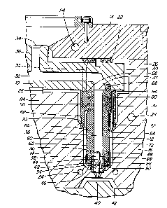
Figure 1 :is a sectional view of a portion of a
multi-cavity injection molding system showing a nozzle
according to a preferred embodiment of the invention, and
~~1~v48~
6
Figure 2 .is an isometric view of the nozzle and
thermocouple element: seen in Figure 1.
DET~~ILED 17ESCRIPTION OF THE INVENTION
Reference is first made to Figure 1 which shows
a portion of a multi-cavity injection molding system or
apparatus having a melt distribution manifold to
interconnecting several heated nozzles 12 in a mold 14.
While the mold 14 usually has a greater number of plates
to depending upon the application, in this case only a cavity
plate 16 and a back plate 18 which are secured together by
bolts 20 are shown for ease of illustration. The melt
distribution manifold 10 is heated by an integral
electrical heating element 22 and the mold 14 is cooled by
pumping cooling water through cooling conduits 24. The
melt distribution manifold 10 is mounted between the cavity
plate 16 and t:he back plate 18 by a central locating ring
26 and insulavtive a.nd resilient spacer members 28 which
provide an insulative air space 30 between the heated
manifold 10 and the surrounding cooled mold 14.
A melt passage 32 extends from a central inlet 34
in a cylindrical inlet portion 36 of the manifold 10 and
branches outwardly in the manifold 10 to convey melt
through a central melt channel 38 in each of the heated
nozzles 12. T:he melt then flows to a gate 40 leading to a
~1~1~~~
7
cavity 42 through a torpedo 44 which is seated between the
front end 46 oi= the nozzle 12 and the cavity plate 16. The
torpedo 44 ha;~ a pair of spiral blades 48 connecting a
central shaft 50 to an outer collar 52 which bridges
another insulative air space 54 extending between the
nozzle 12 and the surrounding mold 14. While the torpedo
44 is shown screwed into the front end 46 of the nozzle 12
in this configuration, in other applications a nozzle seal
or gate insert can be: provided to bridge the insulative air
space 54.
Each steel nozzle 12 has a rear collar portion 56
adjacent a rear end __°i8 and a front portion 60 which extends
forwardly from the rear collar portion 56. The front
portion 60 has: a generally cylindrical outer surface 62
which is smaller in diameter than the outer surface 64 of
the rear collar portion 56. The nozzle 12 is heated by an
integral electrical heating element 65 which extends around
the central me7.t channel 38 to an external terminal 67. In
this embodiment, the: nozzle 12 is seated in a well 66 in
the cavity plate 7.6 by a cylindrical insulating and
locating flange.68 which extends forwardly from the rear
collar portion 56 to sit on a circular shoulder 70 in the
well 66. This provides the insulative air space 54 between
the outer surface 62 of the front portion 60 of the heated
nozzle 12 and the surrounding generally cylindrical inner
~109~f89
8
surface 72 of the well 66 in the cooled mold 14. The
nozzles 12 are secured by bolts 74 to the manifold in a
position with the inlet 76 to the melt channel 38 in each
nozzle 12 in exact alignment with one of the branches of
the melt passage 32.
The nozzle: 12 has a thermocouple element duct 78
extending through the rear collar portion 56 to the
insulative air space 54. In this embodiment, a hollow
thermocouple element tube 80 made of stainless steel
extends throucfh the thermocouple element duct 78 in the
rear collar portion 56 and along the inner surface 82 of
the insulating and locating flange 68. The thermocouple
element tube 80 is brazed in place to be an integral part
of the nozzle :L2. A:~ best seen in Figure 2, a thermocouple
element groove 84 extends in the rear end 58 of the nozzle
12 from the i:hermocouple element duct 78 to the outer
surface 64 of 'the rear collar portion 56. Also, the front
portion 60 of i:he no~.zle 12 has a thermocouple element bore
86 extending a preds~termined distance rearwardly from the
front end 46~. If there is sufficient room, the
thermocouple element bore 86 can extend diagonally inward
as shown.
Before assembly of the injection molding system
or apparatus, a thermocouple element 88 is removably
mounted on each noz;~le 12 as seen in Figure 2. A front
I
9
portion 90 of thE: thermocouple element 88 having a
thermocouple (not shown) is inserted as far as possible
into the therm~ocoup7_e element bore 88 in the front portion
60 of the noz~:le 12. The thermocouple element 88 is then
bent to extend rearwardly along the outer surface 62 of the
front portion 60 of the nozzle 12 and through the hollow
thermocouple s:lemeni: tube 80 in the thermocouple element
duct 78 through the rear collar portion 56 of the nozzle
12. A rear portion 92 of the thermocouple element 88 is
then bent to extend outwardly through the thermocouple
element groove 84 in the rear end 58 of the nozzle 12. The
thermocouple element 88 has leads extending in a protective
casing from the thermocouple to conventional equipment (not
shown) for monitoring the operating temperature. The
casing is made of stainless steel or other material which
is suitably bendabl~e and retentive to be securely self-
retained in place with the front portion 90 of the
thermocouple element 88 extending rearwardly in the
thermocouple element bore 86 and the rear portion 92 of the
thermocouple element 88 extending outwardly in the
thermocouple e:lemeni~ groove 84. This ensures that the
thermocouple in the front portion 60 of each thermocouple
element 88 i~; accu.rately retained in position in the
thermocouple element: bore 86 during installation of the
nozzles 12 in 'the mold 14.
10
In u:ae, the inj ection molding system or apparatus
is assembled as shown in Figure 1. While only a single
nozzle 12 and cavity 42 are shown for ease of illustration,
it will be appreciated that the melt distribution manifold
10 normally has many more melt passage branches extending
to numerous cavities 14, depending on the application. As
can be seen :in Figure 1, the thermocouple element 88
extends rearwa.rdly through the insulative air space 54
between the outer surface 62 of the front portion 60 of the
l0 nozzle 12 and i~he surrounding inner surface 72 of the well
66 and outwardly in the thermocouple element groove 84 in
front of the melt dListribution manifold 10. Electrical
power is applied to 'the heating element 22 in the manifold
and to the h~eatinc~ elements 65 in the nozzles 12 to heat
them to a predetermined operating temperature. Pressurized
melt is applied from a molding machine (not shown) to the
central inlet 76 of the melt passage 32 according to a
predetermined cycle., The melt flows through the melt
distribution manifold 10, nozzles 12, torpedoes 44, and
gate 40 into the cavities 42. After the cavities 42 are
filled and a suitable packing and cooling period has
expired, the injection pressure is released and the melt
conveying systE:m is dLecompressed to avoid stringing through
the open gates 40. The mold 14 is then opened to eject the
molded product:. After ejection, the mold 14 is closed and
~'90~4~9
11
the cycle is repeated continuously with a cycle time
dependent upon the size of the cavities 42 and the type of
material being molded.
Whi7_e the description of the injection molding
nozzle according t~o the invention has been given with
respect to preferred embodiments, it will be evident that
various other modifications are possible without departing
from the scope of the invention as understood by those
skilled in thE: art <~nd as defined in the following claims.
15
25