Language selection

Search

Patent 2101481 Summary

Third-party information liability

Some of the information on this Web page has been provided by external sources. The Government of Canada is not responsible for the accuracy, reliability or currency of the information supplied by external sources. Users wishing to rely upon this information should consult directly with the source of the information. Content provided by external sources is not subject to official languages, privacy and accessibility requirements.

Claims and Abstract availability

Any discrepancies in the text and image of the Claims and Abstract are due to differing posting times. Text of the Claims and Abstract are posted:

  • At the time the application is open to public inspection;
  • At the time of issue of the patent (grant).
(12) Patent: (11) CA 2101481
(54) English Title: COMBINATION COBBLE COVER AND GUIDE TROUGH FOR ROLLING MILL
(54) French Title: ENSEMBLE COUVERCLE ET AUGE DE GUIDAGE POUR LAMINER
Status: Term Expired - Post Grant Beyond Limit
Bibliographic Data
(51) International Patent Classification (IPC):
  • B21B 39/00 (2006.01)
  • B21B 39/14 (2006.01)
  • B21B 39/16 (2006.01)
(72) Inventors :
  • PANACCIONE, LOUIS T. (United States of America)
(73) Owners :
  • SIEMENS INDUSTRY, INC.
(71) Applicants :
  • SIEMENS INDUSTRY, INC. (United States of America)
(74) Agent: SMART & BIGGAR LP
(74) Associate agent:
(45) Issued: 1996-10-15
(22) Filed Date: 1993-07-28
(41) Open to Public Inspection: 1994-06-15
Examination requested: 1993-07-28
Availability of licence: N/A
Dedicated to the Public: N/A
(25) Language of filing: English

Patent Cooperation Treaty (PCT): No

(30) Application Priority Data:
Application No. Country/Territory Date
07/990,674 (United States of America) 1992-12-14

Abstracts

English Abstract


A rolling mill has a roll stand with work rolls defining a roll pass. The roll stand is
removably mounted at an operative position at which its roll pass is aligned with the mill
rolling line. A cover assembly is configured and dimensioned to cooperate in a closed
position with roll stand to enclose the work rolls. A guide trough is integrally associated with
the cover assembly. The cover assembly is alternatively adjustable from its closed position
to either an open position allowing access to the work rolls when the rolls stand is in its
operative position, or to a guide position at which the guide trough is aligned with the mill
rolling line when the roll stand is removed from its operative position.


French Abstract

Laminoir possédant une cage équipée de cylindres de travail définissant une passe. La cage de laminoir est montée de manière amovible en position de fonctionnement où sa passe est alignée avec la ligne de laminage. Un couvercle est configuré et dimensionné de manière à coopérer en position fermée avec la cage de laminoir pour enfermer les cylindres de travail. Une rigole de guidage est intégrée au couvercle. Le couvercle est, en alternance, réglable de sa position fermée, soit à une position ouverte permettant d'accéder aux cylindres de travail lorsque la cage de laminoir se trouve en position de fonctionnement, soit à une position de guidage dans laquelle la rigole de guidage est alignée avec la ligne de laminage lorsque la cage de laminoir n'est plus en position de fonctionnement.

Claims

Note: Claims are shown in the official language in which they were submitted.

The embodiments of the invention in which an exclusive property
or privilege is claimed are defined as follows.
1. In a rolling mill having a roll stand with work rolls defining a roll pass, said
roll stand being removably mounted at an operative position at which said roll pass is aligned
with a rolling line, the improvement comprising:
a cover assembly configured and dimensioned to cooperate in a closed position with
said roll stand to enclose said work rolls;
a guide trough integrally associated with said cover assembly;
a carrier structure for supporting said cover assembly independently of said roll
stand; and
adjustment means associated with said carrier structure for alternatively moving said
cover assembly from said closed position to either an open position allowing
access to said work rolls when said roll stand is in said operative position, or
to a guide position at which said guide trough is aligned with said mill pass
line when said roll stand is removed from said operative position.

2. The apparatus as claimed in claim 1 wherein said cover assembly is rotatably
mounted on said carrier structure for movement between said positions.
3. The apparatus as claimed in claim 2 wherein said cover assembly is rotatable
about an axis parallel to said rolling line.
4. The apparatus as claimed in claim 3 wherein said guide trough comprises as
a plurality of guide elements extending in parallel relationship with said axis.
5. The apparatus as claimed in claim 1 wherein said guide trough extends
through and is removably mounted within said cover assembly, and wherein said cover
assembly is provided with means for providing access to said guide trough.
6. The apparatus as claimed in claim 1 wherein said cover assembly is supported
by said roll stand when in said closed position.

7. The apparatus as claimed in claim 1 wherein said carrier structure is fixed in
relation to said pass line and free standing with respect to said roll stand.
8. The apparatus as claimed in claim 1 further comprising stop means on said
carrier structure for locating said cover assembly in said guide position.
9. The apparatus as claimed in claim 8 further comprising clamp means for
releasably urging said cover assembly against said stop means.

Description

Note: Descriptions are shown in the official language in which they were submitted.


2 ~ O I ~ 8 1
COMBINATION COBBLE CCVER AND GUIDE TROUGH FOR ROLLING MILL
B,~(~KGROI~T~'D OF TIIE II'~VENTION
1. Field Of The Invention
This inven~ion relates generally to rod and bar rolling mills, and is conccrned
in particular wi~h an improvemen~ in guide troughs of the type employed to replace roll stands
when they are removed from the rolling line.
2. Description of the Prior Art
Conventionally, when a roll stand is removed from the rolling line, it is
replaced by a guide trough so that the rolling process may continue. The guide troughs are
normally kept in a storage area remote from the rolling line, and must be transported by
overhead cranes to the rolling line where they are manually clamped into position. This
procedure is time consuming and requires the attention of several operating personnel in
addition to the crane operator.
An objective of the present invention is to facilitate the task of locating and removing
guide troughs in a rolling mill. Related objectives of the present invention include reducing
the time required to manipulate the guide troughs into and out of position, thereby reducing
costly mill down time.
A further objective of the present invention is to provide means for manipulating guide
troughs w ithout requiring the attention of numerous operating personnel, and without
requiring the use of overhead cranes and other auxiliary equipment.
A

SUMMARY OF THE INVENTION 2 1 0 1 4 8 1
These and other objects and advantages of the present invention are realized by
integrally incorporating the guide troughs into the cover assemblies normally employed along
the rolling line to enclose the work rolls and thereby safeguard operating personnel from cobble-
related mishaps. The cover assemblies are mounted for adjustable movement from their normal
closed positions either to open positions allowing access to the work rolls when the roll stands
remain operatively positioned along the rolling line, or alternatively to guide positions at which
the troughs are aligned with the rolling line when the roll stands are removed therefrom.
Adjustment of the cover assemblies between their multiple operative positions is achieved by
powered operating mechanisms, without requiring the assistance of overhead cranes or the like.
According to one aspect of the present invention there is provided in a rolling mill
having a roll stand with work rolls defining a roll pass, said roll stand being removably mounted
at an operative position at which said roll pass is aligned with a rolling line, the improvement
comprising: a cover assembly configured and dimensioned to cooperate in a closed position with
said roll stand to enclose said work rolls; a guide trough integrally associated with said cover
assembly; a carrier structure for supporting said cover assembly independently of said roll stand;
and adjustment means associated with said carrier structure for alternatively moving said cover
assembly from said closed position to either an open position allowing access to said work rolls
when said roll stand is in said operative position, or to a guide position at which said guide
trough is aligned with said mill pass line when said roll stand is removed from said operative
position.

2 ~ ~ ~ 4~ 1
BRIEF DESCRIPTION OF THE DRAWINGS
The present invention will become more apparent as the description proceeds with
reference to the accompanying drawings, wherein:
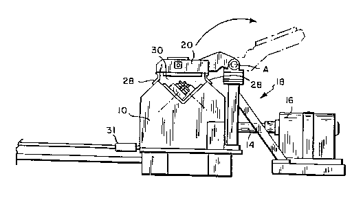
Figure 1 shows a roll stand operatively positioned with its roll pass aligned with the
rolling line, and with the cover assembly in a closed position;
Figure 2 is a view similar to figure 1 showing the roll stand removed from the rolling
line, with the cover assembly adjusted to the guide position;
Figure 3 is a partial view similar to figure 1 on an enlarged scale showing further details
of the cover assembly;
(2a)
f~
~J,

2 1 0 1 ~ 8 1
Figure ~ is a top plan view of Lhe components shown in figure 3;
Figure 5 is a vicw Laken along lines 5-5 of figure 4 and showing thc cover asscmbly
in Lhe open posiLion; and
Figure 6 is a s~c~iona~ view taken along line 6-6 of figure 4 and showing the cover
assembly in the guide position.
D~SCR~PTlON OF ll,I,USTRATED EMBOD~IENT
With refcrence iniLially to figures l and 3, a roll stand 10 is shown operatively
positioned with the roll pass defined by its work rolls 12 aligncd with the rolling line P. The
operatively positioned roll stand is mechanically coupled via a spindle 14 to a mill drive
motor 16.
A carrier structure generally indicated at 18 is located adjacent to the rolling line P.
A cover assembly 20 is supported on the carrier structure independently of the roll stand for
rotational movement about an axis A extending in parallel relationship to the mill rolling line
P. As can best seen by further reference to figure 4, the cover assembly is subdivided into
multiple sections 20a~ 20b~ each being rotatably adjustable about axis A by means of a rotary
actuator 22.
A guide trough 24 is located within and integrally ~ccoci~ted with each cover assembly
segment 20a~ 20b. The guide troughs are of a known design, and are accessible via lids 26
in the roof of each cover assembly segment. When the lids are open, the guide troughs may
be serviccd, and/or removed for replacement by differently sized components configured to

21 01 481
handle differenlly sized products.
When in the closcd posi~ion as illustrated in figures 1, 3 and 4, the cover assembly
rcsts on parallel support flanges 28 forming part of the roll stand 10. The closed cover
assembly cooperates with the underlying roll stand to confine the work rolls 12 within an
enclosed space 30, thereby safeguarding operating personnel from cobble-related mishaps.
When the cover assembly is in the closed positioned, its integrally associated guide troughs
24 are inoperatively located above the rolling line P.
When access to the work rolls is required, for example when work rolls must be
replaced, the rotary actuators 22 are energized to swing the cover assembly segments
upwardly to the fully opened position illustrated by the broken lines in figure 1 and illustrated
in further detail in figure 5.
When removing a roll stand from the rolling line, a procedure commonly referred to
as "dummying~, the cover assembly segments are first rotated to their fully opened positions.
An appropriate transfer mechanism 31 is then utilized to shift the roll stand away from the
rolling line to an inoperative position as shown for example in figure 2. During this
proccdure, a stub shaft 32 on the roll stand is simply decoupled from the spindle 14, the latter
remaining in place. Thereafter, the cover assembly segments are rotated to the guide
positions shown in figure 2, and in greater detail in figure 6. When thus positioned, the
guide troughs 24 of the cover assembly segments are aligned with the.rolling line P. Arms
34 on the cover assembly segments rest on stops 36 on the carrier structure. The arms 34
include inclined rarnps 38 which are engaged by piston-~ctl~ted wedges 40 employed to
securely lock the cover assembly segments in place.
-- 4 --

2 1 0 1 '~ ~3 1
In light of the foregoing, it will now be appreciated by those skilled in the art that by
integra~ly incorporating guide troughs into cover assemblies which are rotatably adjustable
with respcct to the rolling line, significant advantages are obtaincd. The guide troughs may
~uicl;ly and reliably be positioned in place of dummied roll stands without having to resort
to overhead cranes and the like. The cover assemblies and their integral guide troughs thus
serve multiple functions, each of which can be selec~ed with minimal effort on the part of
operating personnel.
I claim:

Representative Drawing
A single figure which represents the drawing illustrating the invention.
Administrative Status

2024-08-01:As part of the Next Generation Patents (NGP) transition, the Canadian Patents Database (CPD) now contains a more detailed Event History, which replicates the Event Log of our new back-office solution.

Please note that "Inactive:" events refers to events no longer in use in our new back-office solution.

For a clearer understanding of the status of the application/patent presented on this page, the site Disclaimer , as well as the definitions for Patent , Event History , Maintenance Fee  and Payment History  should be consulted.

Event History

Description Date
Inactive: Expired (new Act pat) 2013-07-28
Letter Sent 2010-12-07
Inactive: IPC from MCD 2006-03-11
Inactive: Acknowledgment of s.8 Act correction 1998-04-07
Inactive: S.8 Act correction requested 1997-08-27
Grant by Issuance 1996-10-15
Application Published (Open to Public Inspection) 1994-06-15
All Requirements for Examination Determined Compliant 1993-07-28
Request for Examination Requirements Determined Compliant 1993-07-28

Abandonment History

There is no abandonment history.

Owners on Record

Note: Records showing the ownership history in alphabetical order.

Current Owners on Record
SIEMENS INDUSTRY, INC.
Past Owners on Record
LOUIS T. PANACCIONE
Past Owners that do not appear in the "Owners on Record" listing will appear in other documentation within the application.
Documents

To view selected files, please enter reCAPTCHA code :


To view images, click a link in the Document Description column. To download the documents, select one or more checkboxes in the first column and then click the "Download Selected in PDF format (Zip Archive)" or the "Download Selected as Single PDF" button.

List of published and non-published patent-specific documents on the CPD .

If you have any difficulty accessing content, you can call the Client Service Centre at 1-866-997-1936 or send them an e-mail at CIPO Client Service Centre.


Document
Description 
Date
(yyyy-mm-dd) 
Number of pages   Size of Image (KB) 
Cover Page 1995-06-10 1 41
Abstract 1995-06-10 1 30
Claims 1995-06-10 3 140
Drawings 1995-06-10 5 276
Description 1995-06-10 5 241
Cover Page 1996-10-15 1 13
Abstract 1996-10-15 1 17
Description 1996-10-15 6 168
Drawings 1996-10-15 5 102
Claims 1996-10-15 3 50
Description 1998-04-07 6 164
Cover Page 1998-04-07 2 39
Claims 1998-04-07 3 55
Representative drawing 1998-08-14 1 9
Correspondence 1997-08-27 2 74
Fees 1999-07-07 1 45
Fees 1996-06-27 1 48
Fees 1995-06-22 1 54
Courtesy - Office Letter 1996-09-19 1 69
Prosecution correspondence 1996-08-06 2 40
Prosecution correspondence 1994-07-22 2 71
Prosecution correspondence 1994-09-14 7 139
PCT Correspondence 1996-08-06 1 57