Note: Descriptions are shown in the official language in which they were submitted.
WO93/12396 ~ rj 2 c~ PCT/US92/10270
l Title
MELTING APPARATUS AND Method
Technical Field
This invention relates to a melting apparatus for
particulate material. More specifically, it relates to a
gas fired apparatus for melting a freestanding pile of
particulate feedstock in a cubic melting chamber.
Background of ~he Invention
; Prior art apparatuses for melting particulate material
generally utilized the off-gases of the melting process to -
l0 preheat the feedstock by forcing the off-gases through the
feedstock outside the melting chamber. To do this
effectively, required the feedstock mass to be relatively
homogeneous so as to provide uniform permeability and that
this uniform permeability be maintained from the beginning
d 15 of the preheating step to its end. Otherwise, the flow of
off-gases would become channelized and overheat some
portions of the feedstock while leaving other portions
unheated. Localized hot and cold spots caused clumping
which impeded the uniform movement of feedstock into the
1l 20 melting chamber. In severe cases, an entire layer of
i feedstock might coalesce and form a bridge across the
feedstock entry to the melting chamber and thus stop the
, flow of material completely. Furthçrmore, where the prior
~ art apparatus called for all the off-gases from the melter
d 25 to be cycled through a column of feedstock in a vertical
shaft preheater, any impairment or stoppage of the flow of
off-gases would produce a corresponding impairment or
stoppage of the melting process.
':
-
WO93/12396 ~ PCT/US92/10270
l Disclosure of the Invention
It is a general object of this invention to provide a
melting apparatus that is capable of efficiently handling
and melting not only a particulate feedstock mass which is
homogeneous and has uniform permeability but also one which
5 is heterogeneous and does not have uniform permeability. It
is another object of this inventionito provide a melting
apparatus that is capable of melting a particulate feedstock
mass which contains a wide variety of partical sizes and
shapes. For example, in the production of mineral fibers,
lO the feedstock mass may include or be comprised of particles
such as large pieces of crushed or uncrushed rock, typically
measuring between two and five inches, as well as smaller
pieces ranging all the way down to fines or even recycled
product in the form of wads of loose or coagulated fibers.
15 It is another object of this invention to provide a
geometric relationship between a feedstock pile
configuration and the thermal radiating refractory surfaces
of the melting chamber that will optimize heat transfer to
the surface of the pile, particularly a pile of feedstock
20 material that is opaque to the radiation. It is still
another object of this invention to create a toroidal flow
of burner gases in a square melting chamber so that a
negative pressure vortex region can be induced at a
feedstock charge opening located in the center of the
25 chamber roof. It is yet another object of this invention to
3 provide a method of melting particulate feedstock whereby
~ fresh feedstock is fed onto the surface of a freestanding
WO93/12396 ?, '.!~ 2 ~ PCT/US92/10270
1 pile of previously charged feedstock, which surface is at or
; above incipient melting temperature.
The melting appàratus of this invention is for melting
~: a freestanding pile of particulate material in a chamber by
means of gas fired burners utilizing waste heat recovered
5 from off-gases by an adjoining recuperator. The chamber is
defined by four successively connected planar vertically
disposed wall members of substantially equal length, a floor
member and a roof member. A preheated air-fuel fired burner
is mounted in each wall member adjacent to the corner formed
10 by the tail end of one wall member and the head end of a
successive wall member. The axis of each burner lS parallel
{ with its successive wall member so the combined effect of
the burners is to produce a toroidal flow of combustion
products in the melting chamber around its central vertical
15 axis. The melting apparatus includes a forehearth assembly
r~ with two or more fuel fired forehearths connected to the
downstream end of a distributor. Molten product flows from
the melting chamber into the distributor which has a sump
where any of the more dense fractions that might be present
20 in the melt may settle to the bottom thereof and be drained
1 off. Then the melt stream divides and flows into the open
upstream ends of the respective forehearths where the molten
, product undergoes further heating and thermal treatment to
prepare it for final processing by extraneous equipment,
25 such as mineral fiber spinning machines. The forehearth
communicates with the melting chamber through an inlet
opening in one wall member of the chamber. A recuperator,
, for providing preheated air to the melting chamber burners
.
., ' .' .
W O 93/12396 P ~ /US92/10270
2 ~ h Vl
1 and the forehearth burners, communicates with the melting
chamber through an outlet opening in a wall member on the
side of the melting chamber opposite from the forehearth
inlet wall member. A charge opening is provided in the
center of the roof member to admit feedstock to the melting
S chamber. ~ -
The various features, their relationship to one another
~ and their advantages will be understood best if the
: following description of a preferred embodiment is read in
conjunction with the accompanying drawings.
10 Brief Description of the Drawings
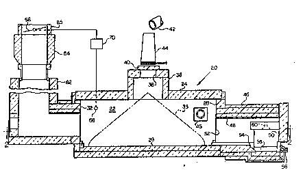
Fig. 1 is a vertical sectional view of the melting
. . .
apparatus of this invention, with parts broken away, taken
along lines 1-1 of Fig. 2, and
Fig. 2 is a sectional plan view of slightly reduced
size taken along lines 2-2 of Fig. 1.
Best Mode of Carrying Out the Invention
Generally speaking, the melting apparatus 20
illustrated in the drawings is comprised of a melting
, chamber 22 having a square horizontal cross section. It is
~ 20 defined by refractory wall members including a horizontal
,~ roof member 24, a horizontal floor member 26 and four
sucessively connected vertically disposed sidewall members
.
~! 28, 30, 32, 34 of equal length forming the periphery of the
chamber. The cross sectional shape of the melting chamber ~-
r~, 25 need not be exactly square but any deviation should be
limited to a point such that the chamber remains effectively
square for the purposes involved. Preferahly, the inside
~ .
surface of each of these members is substantially planar so
-,~
;,
WO93/12396 ~ , 3 PCT/US92/10270
l as to provide efficient thermal radiation and reradiation
between the wall members and the feedstock pile.
An important detail of the invention is the relative
size of its members. Ideally, the inside length-to-height
ratio of each sidewall member 28, 30, 32, 34 is 3 : l. This
relationship provides the most effective heat transfer to
the surface of a freestanding pile 35 (shown in phantom
lines) of feedstock deposited on the floor of the melting
' chamber. ~nder extenuating circumstances other ratios
between 2.2 : l and 4.4 : l may be used, but in most
l0 instances melting efficiency will be reduced. -
A charge opening 36 for admitting particulate feedstock
to the melting chamber 22 is located in the center of ro~f -
member 24. Preferably the charge opening 36 is spaced above ~l -
the roof of the chamber by means of a short vestibule or
15 shaft section 38 which has a square internal cross section
~ that is symmetrically disposed with respect to the melting
,' chamber. The inside height of the shaft section 38 is less
' than its width and the ratio of width-to-height is less than
the length-to-height ratio of the melting chamber sidewalls.
20 Opening 36 is covered by a removable closure or lid 40.
Conveying means 42 is provided for supplying particulate
, feedstock continuously or intermittently to the melting
'1 , chamber through the access opening 36. It may include an -
c accumulating hopper assembly 44 in the event charging of the
25feedstock is to occur intermittently by batches.
~, ~nder normal operating conditions, the base of the ~.
; feedstock pile 35 will extend laterally into proximity with
the central bottom portion of each of the four sidewalls and '~
WO93/12396 '?';~ r' 2 ~ PCT/US92/10270
'J
l the apex will extend vertically into the bottom of vestibule
shaft section 38. Accordingly, the outside surface of the
freestanding feedstock pile is slanted inwardly from bottom
to top giving it a generally conical configuration. The
inclination of the pile surface is fairly constant overall
except for a bottom portion of the pile where it drops off
precipitously, as shown in Fig. l. The words "generally
conical configuration" are intended to include a conical
pile with its bottom edge portion melted away as well as a
similar pile in the form of a pyramid with a square cross
lO section. Feédstock piles having pyramidal portions may
occur when the apex of the pile is allowed to extend into
the shaft 38 and be influenced by contact with the square
shape of the exit end of the shaft during the charging
` process.
The overall geometric relationship between the
refractory surface areas of the square melting chamber and
~ the slanting surface areas of the feedstock pile enhances
i the melting process. It is important to note that in this
;~ relationship the horizontal distance between the thermal
20 radiating surface areas of the melting chamber sidewall
member~ and the corresponding feedstock pile surface areas
decreases continuously from top to bottom. Similarly, the
vertical distance between the thermal radiating surface
areas of the melting chamber roof member and the
25 corresponding feedstock pile surface areas decreases
continuously from the sides of the chamber to the vestibule
in its center. Also, the ratio of the total thermal
radiating surface area of the sidewall members to the
'' .
. ., , . . . : : . ~
: . : ,
WO93/12396 2 ~ O i ~ PCT/US92/10270
1 corresponding feedstock pile surface area at a given level
increases continuously from bottom to top.
A high temperature burner 45 designed to operate with a
fluid fuel and preheated combustion air is mounted in the
tail end of each melting chamber sidewall member adjacent to
S the junction formed by the tail end of its wall member and
the head end of the next succeeding wall member. Natural
gas fuel is preferred but other fluid fuels can be used.
The axes of the burners are perpendicular to the inside
surface of their sidewall members and thus are parallel to
the roof member surface as well as the surface of the
succeeding sidewall member. Each of the burners 45 is
located in the upper half of its sidewall member.
Preferably, each of them is located, relative to the surface
of the feedstock pile, roof member and succeeding sidewall
member, such that its axis is equidistant from the roof
member surface, its succeeding sidewall member surface and
the surface of the pile at the nearest point, as can be seen
in Fig. 1. This arrangement provides the most efficient
transfer of heat to the surface of the feedstock pile and
, 20 produces a toroidal mass flow of combustion products around -
the vertical centerline of the melting chamber. On the
outside of the toroidal flow zone are four relatively
quiescent mass flow zones, each involving a volume of space
adjacent to one of the corners formed by the sidewall member
; 25 junctions. Fine particles of matter entrained in the
mainstream of toroidally flowing gases tend to drop out of
the stream when they reach a quiescent zone. The floor
~ areas beneath these quiescent zones are of substantial size
'< . ~,
. ~ .
~ .,, :~:. , , ,, . ~ , :
W093/12396 PCT/US92/10270
2~ ~ 5 ~ 8
l and lie outside of the perimeter of the feedstock pile.
Shallow pools of molten product from the feedstock pile
collect in these areas while a portion thereof is allowed to
flow out of the melting chamber as needed. The surface of
the molten material in these areas is exposed to a
substantial amount of thermal radiation and thus undergoes
some initial refining which may entail oxidation, if
desired, and equalization of temperature.
A forehearth assembly 46, which includes a distributor
passageway 48 and at least one fuel fired elongated
lO forehearth 50, communicates with the melting chamber via an
entrance opening 52 on the upstream end of the distributor.
The entrance opening 52 extends through the bottom portion
of a melting chamber sidewall member midway between its
ends. Although the melting apparatus
.. . .
15 will operate efficiently with only one fuel fired
forehearth, the preferred embodiment has at least two of -
such forehearths. It has been found that the overall
efficiency of the melting apparatus, measured by the total
fuel required to produce a unit of molten product at a given
; 20 temperature, is increased by the use of more than one fuel
fired forehearth in combination with one melting chamber
` rather than pairing a melting chamber one-to-one with a fuel
fired forehearth.
Distributor passageway 48 has a rectangular internal
25 cross section and is defined by planar refractory walls.
! Its bottom wall or floor, at the entrance opening and for a
distance downstream therefrom, is level with the melting
chamber floor. A downwardly inclined ramp 54 extends from
., .
:'
. . ~ - , . .
. - ,.: ; ,.. . ~ , ,. :
: ....... ,: .. . . :
W O 93/12396 2 ~ P ~ /US92/10270
1 the downstream end of this level section to a collection
sump 55. Molten product containing fractions having varing
densities flows down the ramp into the su~p which has a
bottom that is the lowest area in the run. The more dense
fractions of molten product settle to the bottom of the sump
where they are drawn off through a tap 56. After passing
into the sump section, the less dense fractions of the
molten product in the upper level of the sump divide and
flow towards the distal ends of the elongated forehearths
50.
The forehearths are identical in size and have
, rectangular cross sectional interiors with width, height and
; length relationships such that their widths equal or exceed
." , . .
their heights and their length-to-width ratios are greater
than 3 : 1. A plurality of downwardly directed flat flame
burners 60, shown in phantom lines in Fig. 2, provide high
intensity heat transfer to the molten product on the floor
of the forehearths. They are located in the roof of each
forehearth and arranged singly at equal intervals along its
longitudinal centerline. Their purpose is to raise the
temperature of the incoming melt to the final temperature ~
required for processing. For example, in the production of - -
mineral fibers the mean temperature of the melt entering the
forehearth is nominally 1400 degrees C. and the final
temperature is 1500 degrees C. The relatively particle free
combustion products from these forehearth burners flow out
through the distributor passageway into the melting chamber
where they enter the chamber between two quiescent zones.
Thereafter they mix with and supplement the toroidally
' ~, ' . .' ' ;. ,. : ~ ' .' ' : ` " ', " : . ', - ' ' ,
".'' i ~ r'
:::: ' ~ ' '. . ` . ~ ' ::: : ' . :
: j . ' ' ' . ' :: ' .'. , , : ' ' ' ' ~ , , ' . . '
WO93/12396 PCT/US92/10270
~ 1 Q i 3 ~ ~
1 flowing combustion products generated by the melting chamber
burners. Partially refined molten product flowing out of
the distributor into the respective forehearths is raised in
temperature and may be given additional thermal treatment as
it travels through them. When the melting apparatus is
5 being used to melt rock material for use in the production
of mineral fibers, the refining includes bringing the molten
product to a higher uniform working temperature and in the
process oxidizing unoxidized portions thereof. Oxidization
of the molten product reduces its ther~al opacity and
1 thereby improves heat transfer to the molten product. The
refined molten product may then be conveyed from the distal
ends of the forehearths to their respective mineral wool
spinning machines tnot shown).
A recuperator assembly 62, attached to the melting
5 chamber sidewall member on the side of the chamber opposite
from the forehearth sidewall member, communicates with the
interior of the melting chamber through an exit opening in
, the center thereof, which opening is likewise located
between two quiescent zones. The recuperator assembly
includes a recuperator section 64 and a stack section 65.
Its purpose is to extract heat from the off-gases flowing
out of the melting chamber and transfer the recovered heat
to the combustion air being supplied to the burners.
~ Additionally, the recuperator assembly provides a means for
s automatically developing a negative pressure at the
feedstock charge or entry opening 36. This is accomplished
i by means of sufficient stack height, a pressure sensor 66 in
.;
:. .: : :; ; . ; ... : . .. - ~ ~ . :. . . . : , . , - . .
WO 93/12396 ~ 3 PCT/US92/10270
11
1 the melting chamber, a draft control mechanism including a
damper 68 in the stack and a programmed controller 70.
To begin the melting process the particulate material
is fed into the cubic melting chamber of the melting
apparatus through the feedstock charge opening in the center
of the roof of the chamber in an amount sufficient to
produce a freestanding generally conically shaped pile which
extends from the floor of the melting chamber to its roof.
j A toroidal flow of hot combustion products is generated
; around the vertical axis of the pile by means of the
10 preheated air type fluid fuel burners located in the upper
half of said chamber adjacent to the corners thereof. The ,
, temperature of the combustion products emanating from these
burners is sufficient to maintain the refractory surfaces of
the chamber walls at a radiant temperature which is above
' 15 the melting point of the particulate material on the surface
.
s of the pile. As the particulate material meits the molten
portion flows downward to the floor of the chamber and
subsequently from there into a forehearth assembly. In the
event the resultant molten product contains an unwanted
20 fraction of higher density material, a sump may be provided
at the entrance of the forehearth assembly where this higher
, density fraction can settle out and be tapped off.
Normally, the molten product on the floor of the forehearth
will be raised to a higher temperature by means of flat
, 25 flame burners located in the roof of the forehearth
..
~i assembly. These latter burners provide a supplemental
amount of combustion products which is supplied to the
melting chamber from the forehearth assembly through an
. i .
; .'. ~
.. ,:~ .
:!
.,
-: .. :,. , ., - -. .~ ,, ;;. . . .. ,` ....... ':
WO93/12396 ~ i,Ji~ PCT/US92/10270
12
l opening in one side of the chamber. Concurrently, off-gases
from the chamber are exhausted to a recuperator through an
opening in an opposite side of the chamber. Heat is
extracted from these off-gases and transfered to the
combustion air which is supplied in turn to the burners.
Although the above description is limited to one
illustrated preferred embodiment of the melting apparatus
and is directed to the melting of rock for the production of
mineral fibers, it is to be understood that the melting
apparatus may be used for other purposes. It is also to be
lO understood that in using this apparatus for melting rocks or
in adapting it for use in melting other particulate
material, minor modifications will become apparent to those
skilled in the art and such modifications can be made
without departing from the scope of the invention which is
15 defined primarily by the appended claims.
J '
, .
~ 20
.
.
,
. -.
: , , . , . . : ~ .: . .