Language selection

Search

Patent 2101597 Summary

Third-party information liability

Some of the information on this Web page has been provided by external sources. The Government of Canada is not responsible for the accuracy, reliability or currency of the information supplied by external sources. Users wishing to rely upon this information should consult directly with the source of the information. Content provided by external sources is not subject to official languages, privacy and accessibility requirements.

Claims and Abstract availability

Any discrepancies in the text and image of the Claims and Abstract are due to differing posting times. Text of the Claims and Abstract are posted:

  • At the time the application is open to public inspection;
  • At the time of issue of the patent (grant).
(12) Patent: (11) CA 2101597
(54) English Title: SAFETY DEVICE AGAINST RUPTURE OF A ROTARY SHAFT
(54) French Title: DISPOSITIF DE PROTECTION CONTRE LE BRIS D'UN ARBRE TOURNANT
Status: Expired and beyond the Period of Reversal
Bibliographic Data
(51) International Patent Classification (IPC):
  • E06B 09/08 (2006.01)
  • E06B 09/56 (2006.01)
  • E06B 09/84 (2006.01)
(72) Inventors :
  • KRAEUTLER, BERNARD (France)
(73) Owners :
  • BERNARD KRAEUTLER
  • NERGECO (SOCIETE ANONYME)
(71) Applicants :
  • BERNARD KRAEUTLER (France)
  • NERGECO (SOCIETE ANONYME) (France)
(74) Agent: NORTON ROSE FULBRIGHT CANADA LLP/S.E.N.C.R.L., S.R.L.
(74) Associate agent:
(45) Issued: 2003-09-09
(22) Filed Date: 1993-07-29
(41) Open to Public Inspection: 1994-01-30
Examination requested: 2000-07-17
Availability of licence: N/A
Dedicated to the Public: N/A
(25) Language of filing: English

Patent Cooperation Treaty (PCT): No

(30) Application Priority Data:
Application No. Country/Territory Date
92-09391 (France) 1992-07-29

Abstracts

English Abstract


A safety device against rupture of a rotary shaft
(1) for preventing the shaft from rotating and for
preventing broken portions thereof from falling, the
device being particularly suitable for use with a shaft
that winds up lifting straps for a raisable curtain or
that winds up the curtain itself, the device being
characterized in that at least one safety element (3, 5)
is placed to retain the shaft to prevent it from falling,
and in that the peripheral surface of the shaft and the
facing surface of said safety element are provided with
means such as portions in relief (2, 6) that co-operate
to prevent the shaft from rotating when a portion of the
shaft is retained by said safety element due to the shaft
rupturing.


Claims

Note: Claims are shown in the official language in which they were submitted.

5
Claims:
1. A safety device against rupture of a rotary shaft for preventing the shaft
from rotating and for preventing broken portions thereof from failing, the
device being
particularly suitable for use with a shaft that winds up lifting straps for a
raisable
curtain or that winds up the curtain itself, the device being characterized in
that at
least one safety element is placed to retain the shaft to prevent the shaft
from falling,
and in that a peripheral surface of the shaft and a facing surface of said
safety element
are provided with means that co-operate to prevent the shaft from rotating
when a
portion of the shaft is retained by said safety element due to the shaft
rupturing.
2. A device according to claim 1, in which the safety element is a bracket
surrounding a bottom portion of the shaft, the inside of the bracket being
provided
with portions in relief, and the surface of the shaft also being provided with
portions
in relief.
3. A device according to claim 1, in which the safety element is a rod
engaged inside a hollow shaft, said hollow shaft having an inside peripheral
wall
including portions in relief suitable for engaging said rod so as to be locked
thereon.
4. A device as defined in claim 1, wherein said means include
cooperating relief portions formed on the shaft and on the safety element.
5. A device as defined in claim 2, wherein the portions in relief of the
bracket include at least one rib, and wherein the portions in relief of the
shaft include
at least one longitudinal groove suitable for engaging said rib to be locked
thereagainst.
6. A device according to claim 3, wherein the portions in relief on said
inside peripheral wall include at least one longitudinal groove.

6
7. A safety device operable in the event of rupture of a rotary shaft for
preventing the shaft from rotating and for preventing broken portions of the
shaft from
falling, for use with a shaft that winds up one of lifting straps for a
raisable curtain and
the curtain itself, characterized in that at least one safety element is
placed below and
along a substantial portion of the shaft to retain the shaft to prevent it
from falling,
wherein a peripheral surface of the shaft and a facing surface of said safety
element
comprise means for cooperatively preventing the shaft from rotating when a
portion of
the shaft is retained by said safety element due to the shaft rupturing.
8. The device according to claim 7, wherein the safety element comprises
a bracket surrounding the bottom portion of the shaft, an inside of the
bracket being
provided with a first member and the surface of the shaft also being provided
with a
second mating member suitable for engaging said first member to thereby lock
said
shaft.
9. The device according to claim 8, wherein said second mating member
comprises at least one longitudinal slot and wherein said first member
comprises a rib
disposed substantially parallel to said longitudinal slot.
10. Device according to claim 7, wherein said shaft is a hollow shaft,
wherein the safety element is a rod disposed inside the hollow shaft, the
inside
peripheral wall of said hollow shaft including a mating member for engaging
with said
rod so as to prevent shaft rotation.
11. The device according to claim 10, wherein said mating member
comprises at least one rib protruding from said inside peripheral wall of said
hollow
shaft.
12. A safety element for a roll up door including a shaft suspended above a
door way, said safety element comprising:

7
first means dispersed parallel to the length of the shaft for supporting
the shaft in the event of a shaft rapture, which rupture thereby moves a
ruptured
portion of the shaft into contact with said first means, and
second means for preventing rotation of said ruptured portion of the
shaft when the ruptured portion of the shaft moves into contact with said
first means.
13. The safety element as recited in claim 12, wherein said first means
comprises a bracket disposed beneath said shale.
14. The safety element as recited in claim 12, wherein said second means
comprises:
a first member operatively supported beneath said shaft;
a second mating member connected to said shaft and opposing said
first member for engaging said first member when said ruptured shaft is moved
into
contact with said first means.
15. The safety element as recited in claim 14, wherein said first member is
a male member and wherein said second mating member is a female member.
16. The safety element as recited in claim 14, wherein said lust member is
a male member and wherein said second mating member is a male member.
17. The safety element as recited in claim 12, wherein said shaft is a
hollow shaft, wherein said first means is a rigid rod member, and wherein said
rod
member is disposed inside of said hollow shaft.
18. The safety element as recited in claim 17, wherein said second means
comprises:
said rod member;

8
a mating member provided on an inside surface of said hollow shaft,
said mating member being brought into engaging contact with said rod member
when
said ruptured shaft is moved into contact with said first means.

Description

Note: Descriptions are shown in the official language in which they were submitted.


1 ~ ~ ~v~ ~ ~ ,~ ~,~
A SAFETY DEVTCE AGAINST RUPTURE OF A ROTARY SHAFT
The present invention relates to a safety device
against rupture of a rotary shaft, in particular a device
intended to stop rotation and to prevent broken portions
of the shaft from falling. The invention is particularly
suitable for the wind-up shafts of raisable curtain
doors. Such a shaft may wind up a flexible curtain of
cloth or plastics material directly or it may wind up
straps which in turn serve to raise the curtain which
may, itself be formed of panels that are rigid or
flexible and that are suitable for folding up above the
doorway.
Such doors are,used in factories and warehouses and
they often have to operate under difficult conditionsa
they may be required to operate several hundreds or even
thousands of times a day, starting and stopping suddenly,
being interrupted roughly in the event of accidents,
shocks, etc. It can happen that a wind-up sha:d:t breaks.
Not only rnay the p:leces of the broken shaft fall to the
ground, thus constituting a first danger, but also, since
the shaft is broken, one of the parts thereof is no
longer braked, and since it is thus free to rotate it
will necessarily allow any door portions such as straps
or curtains that it was supporting to unwind, thus
causing the curtain to be unwound on one side, giving
rise to further risks of parts falling, and also giving
rise to risks that the curtain will tear or be damaged
some other way.
The present invention provides a safety device
against rupture of a rotary shaft for preventing the
shaft from rotating and for preventing broken portions
thereof from falling, the device being particularly
su3.table for use with a shaft that winds up lifting
straps for a raisable curtain or that winds up the
curtain itself, the device being charaeteri~ed in that at
least one safety element is placed to retain the shaft to
prevent it from falling, and in that the peripheral

2
surface of the shaft and the facing surface of said
safety element are provided with means such as portions
in relief that co-operate to prevent the shaft from
rotating when a portion of the shaft is retained by said
safety element due to the shaft rupturing.
In one embodiment, the safety e7Lement is a bracket
surrounding the bottom portion of the shaft, the inside
of the bracket being provided with portions in relief
such as at least one rib, and the surface of 'the shaft
also being provided with portions in relief, such as at
least one longitudinal groove suitable for engaging said
rib to be locked thereagainst.
In another embodiment, the safety element is a rod
engaged inside a hallow shaft, the inside peripheral wall
of said shaft including portions in relief such as at
least one longitudinal groove suitable for engaging said
rod so as to be locked 'thereon.
Other characteristics and advantages of the
invention appear from the following description of an
embodiment of the invention given by way of non-limiting
example and described with reference to the accompanying
drawings, which show cleax°ly how the invention can be
implemented.
In the drawings:
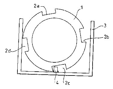
Figure 1 is a section view through a mechanism in
normal operation, the mechanism comprising a wind-up
shaft of the invention and the section being through a
safety element;
F:Lgure 2 is a section view through 'the same elements
after a raisable Curtain door has broken; and
Figure 3 is a section view through a variant
embodiment.
Figure 1 shows a mechanism in normal operation,
Comprising a shaft l Formed by means of a hollow tube
that includes, at least at certain locations therealang,
longitudinal grooves 2a, 2b, 2c, and 2d that have no
effect in norrnal operation. At the locations

~~-..-.~ tc.~.:3 d
corresponding to these portions in relief, safety
elements are disposed beneath the shaft and -they may be
constituted by brackets 3 fitted with at least one
respective rib 4, e.g. in the bottommost portion of the
bracket. The sections o.f the grooves and of the ribs are
designed to lock the shaft against rotation should it
come to bear against 'the bottom of a :bracket. These
portions in relief are therefore made with sharp angles,
e.g. at 90°. The shaft could be provided with ribs
ZO instead of being provided with grooves.
Figure 2 shows the same portion of the shaft 1 after
the shaft has broken. Since the shaft is no longer.
continuous, it drogs, generally being held by joints at
its ends. Tt can clearly be seen from the drawing that
the broken shaft does not fall to the floor, but is
supported by -the bracket which is itself fixed to the
doorframe. Tn addition, the shaft is prevented from
rotating. Thus, in the event of rupture, nothing falls
down, and the broken shaft is immediately prevented from
rotating.
The shaft may have the section shown along its
entire length.
The safety element may extend along the entire
corresponding length, thus having the overall shape of a
gutter. This disposition is suitable for shafts that
wind up lifting straps. A large fraction of the shaft
remains uncovered.
When 'the curtain itself winds onto 'the shaft, the
above~described safety dispositions can be applied only
to the ends of the shaft beyond the region of the shaft
onto which the curtain is wound. Under such
circumstances, other embodiments of the safety device are
possible.
Figure 3 shows a variant in which the safety element
is a rod 5 engaged inside the shaft 1'. Four notches 6a
to 6d are formed in the inside periphery of the shaft,
facing the rod 5. The section of the rod has sharp

d .a. iI
angles so as to prevent the shaft from rotating should i-t
come to rest thereon. The notches 6a to 6d could be
replaced by ribs.
N-aturally, other shapes of relief could be adopted,
the essential points being:
1 - a length of brol~en shaft must be retained so as
to prevent it from falling to the ga~ound; and
2 - it must be prevented from rotating.

Representative Drawing
A single figure which represents the drawing illustrating the invention.
Administrative Status

2024-08-01:As part of the Next Generation Patents (NGP) transition, the Canadian Patents Database (CPD) now contains a more detailed Event History, which replicates the Event Log of our new back-office solution.

Please note that "Inactive:" events refers to events no longer in use in our new back-office solution.

For a clearer understanding of the status of the application/patent presented on this page, the site Disclaimer , as well as the definitions for Patent , Event History , Maintenance Fee  and Payment History  should be consulted.

Event History

Description Date
Time Limit for Reversal Expired 2008-07-29
Letter Sent 2007-07-30
Inactive: IPC from MCD 2006-03-11
Grant by Issuance 2003-09-09
Inactive: Cover page published 2003-09-08
Inactive: Inventor deleted 2003-08-27
Pre-grant 2003-04-30
Inactive: Final fee received 2003-04-30
Notice of Allowance is Issued 2003-01-02
Letter Sent 2003-01-02
Notice of Allowance is Issued 2003-01-02
Inactive: Approved for allowance (AFA) 2002-12-23
Amendment Received - Voluntary Amendment 2002-11-13
Letter Sent 2002-09-19
Reinstatement Requirements Deemed Compliant for All Abandonment Reasons 2002-07-29
Inactive: S.30(2) Rules - Examiner requisition 2002-05-16
Deemed Abandoned - Failure to Respond to Maintenance Fee Notice 2001-07-30
Inactive: Status info is complete as of Log entry date 2000-07-27
Letter Sent 2000-07-27
Inactive: Application prosecuted on TS as of Log entry date 2000-07-27
All Requirements for Examination Determined Compliant 2000-07-17
Request for Examination Requirements Determined Compliant 2000-07-17
Application Published (Open to Public Inspection) 1994-01-30

Abandonment History

Abandonment Date Reason Reinstatement Date
2001-07-30

Maintenance Fee

The last payment was received on 2003-06-13

Note : If the full payment has not been received on or before the date indicated, a further fee may be required which may be one of the following

  • the reinstatement fee;
  • the late payment fee; or
  • additional fee to reverse deemed expiry.

Patent fees are adjusted on the 1st of January every year. The amounts above are the current amounts if received by December 31 of the current year.
Please refer to the CIPO Patent Fees web page to see all current fee amounts.

Fee History

Fee Type Anniversary Year Due Date Paid Date
MF (application, 4th anniv.) - small 04 1997-07-29 1997-07-21
MF (application, 5th anniv.) - small 05 1998-07-29 1998-06-17
MF (application, 6th anniv.) - small 06 1999-07-29 1999-06-23
MF (application, 7th anniv.) - small 07 2000-07-31 2000-06-27
Request for examination - small 2000-07-17
MF (application, 8th anniv.) - standard 08 2001-07-30 2001-07-13
MF (application, 9th anniv.) - standard 09 2002-07-29 2002-07-10
Reinstatement 2002-07-29
Final fee - standard 2003-04-30
MF (application, 10th anniv.) - standard 10 2003-07-29 2003-06-13
MF (patent, 11th anniv.) - standard 2004-07-29 2004-06-16
MF (patent, 12th anniv.) - standard 2005-07-29 2005-06-28
MF (patent, 13th anniv.) - standard 2006-07-31 2006-06-22
Owners on Record

Note: Records showing the ownership history in alphabetical order.

Current Owners on Record
BERNARD KRAEUTLER
NERGECO (SOCIETE ANONYME)
Past Owners on Record
None
Past Owners that do not appear in the "Owners on Record" listing will appear in other documentation within the application.
Documents

To view selected files, please enter reCAPTCHA code :


To view images, click a link in the Document Description column. To download the documents, select one or more checkboxes in the first column and then click the "Download Selected in PDF format (Zip Archive)" or the "Download Selected as Single PDF" button.

List of published and non-published patent-specific documents on the CPD .

If you have any difficulty accessing content, you can call the Client Service Centre at 1-866-997-1936 or send them an e-mail at CIPO Client Service Centre.


Document
Description 
Date
(yyyy-mm-dd) 
Number of pages   Size of Image (KB) 
Representative drawing 1998-08-25 1 8
Representative drawing 2002-12-29 1 7
Description 1994-03-18 4 148
Claims 2002-11-12 4 114
Abstract 1994-03-18 1 20
Drawings 1994-03-18 2 28
Claims 1994-03-18 1 41
Reminder - Request for Examination 2000-03-29 1 117
Acknowledgement of Request for Examination 2000-07-26 1 177
Courtesy - Abandonment Letter (Maintenance Fee) 2002-09-17 1 182
Notice of Reinstatement 2002-09-18 1 170
Commissioner's Notice - Application Found Allowable 2003-01-01 1 160
Maintenance Fee Notice 2007-09-09 1 174
Correspondence 1993-12-13 1 63
Correspondence 2003-04-29 1 39
Fees 2002-07-28 1 48
Fees 1996-07-08 1 63
Fees 1995-07-11 1 55