Note: Descriptions are shown in the official language in which they were submitted.
ADJUSTABLE SUSPENSION SYSTEM FOR HANGING
FOLDERS AND PACKAGE THEREFOR
FIELD OF THE INVENTION
The present invention relates to a suspension
system for hanging file folders and includes
adjustable end frames, which can be used for different
size of hanging folders in different sizes of drawers
or file cabinets, and adjustable, multi-piece rails
for use with the frames. These frames and rails are
suitable for compact storage and shipment in a
package.
HlErCRGRODND
Hanging file folder frames are an essential part
of modern document organization systems, providing
efficient storage and convenient access to documents
placed in vertically arranged pocket-type hanging file
folders. To be of practical value, a hanging folder
frame must be inexpensive to make and easy to
assemble, and have a strong and rigid structure. In
addition, given the diversity of sizes of file folders
and storage cabinets or drawers currently in use, it
is very important that the frames and rails provide
both lateral and longitudinal adjustability in order
to meet the requirements of various different office
settings.
A number of solutions have been proposed in the
past to meet these often contradictory requirements.
Some approaches focus on lateral adjustability of the
hanging folder frame in order to accommodate different
folder sizes. One way to achieve this involves
telescopic horizontal cross-members extendible to
different positions, as shown by U.S. Pat. No.
3,999,663. In this arrangement, the frames are
relatively complex, making them costly and awkward to
- 2- -
adjust. In addition, although providing the desired
adjustability, the frames designed according to this
approach are structurally weak.
Other known solutions involve invertible
assemblies, one end of which is adjusted to
accommodate one type of folders, for instance letter
size, while the inverted frame is adjusted to
accommodate a different type of folders, frequently
legal size document folders. The end frames according
to this approach have a rigid structure as in U.S.
Pat. No. 4,526,277, or can be of an X-shaped
configuration, as in U.S. Pat. No. 4,295,571, both
frames supporting letter and legal size folders. In
each case, the proposed structure only has limited
lateral adjustalbilit~r ~tc~o options) and cannot be used
in a more general setting. Also, the assembly of the
X-shaped frames involves loose hardware and is
complicated.
Other known hanging folder frames are designed in
search of compactness of the overall structure by
means of remo~rable vertical support mountings. An
example is described in U.S. Pat. No. 3,848,748,
wherein the vertical mountings are rotationally
connected to fixed size upper and lower frames by
means of hooks. The vertical support mountings can be
folded and collapsed to occupy minimum space in one
dimension. The upper and lower frames, however, are
of fixed dimensions, corresponding to the maximum
width and length of the supported file cabinets.
Thus, by necessity, any package containing these
components will be quite large in at least one
dimension.
Due to the requirement of rigidity of the support
rails, only relatively few known solutions provide
longitudinal adjustability of the hanging folder frame
_.
- 3
and an associated compact storage feature of the
disassembled structure. Adjustability of the rail
length is typically achieved by means of weakened
notch regions located at the end portions of the
support rails, which weakened regions can be broken
away to obtain the desired length of the rails (U. S.
Pat. No. 3,999,663). While providing the desired
adjustability in length, this approach still has the
disadvantage of requiring a packaging box of the
largest possible dimensions, which makes shipping,
handling and storage inconvenient and costly. In
addition, once adjusted to a specific size, frames of
this type cannot properly be readjusted to exploit the
full capacity of larger size file cabinets.
Longitudinal adjustability is the object of
another type of hanging folder frames, as exemplified
by U.S. Pat. No. 2,852,028, where one rail element is
adjustably sliding in a channel, and is secured to a
second rail element of much shorter length. As in the
previous case, however, the storage box by necessity
must have at least one relatively large dimension.
Also, the assembly of the frame may is complicated.
Thus, no currently used hanging folder system
Provides easy to assemble components, adjustability in
two dimensions (i.e., width and depth), and a
structure which facilitates compact packaging and
storage.
BUMM~Y OF THE INVENTION
The present invention provides a new and
unexpected solution to these problems in a laterally
adjustable frame for supporting a pair of support
rails upon which hanging folders may be suspended.
The frame comprises first and second frame elements
each having a column member and at least one
~~.!31rj~2
substantially horizontal bracket member extending away
from the column member, means for positioning a pair
of support rails at a height which enables suspension
of file folders thereon, and means for adjustably
connecting the first and second bracket members to
position the column members in a spaced relation
corresponding to a predetermined adjustable distance
between the support rails positioning means.
The adjustable connecting means preferably
comprises a plurality of apertures positioned in
spaced relation along a horizontal bracket member of
one frame element and a plurality of locking elements
positioned along a horizontal bracket member of the
other frame element. The locking elements are
positioned in spaced relation corresponding to the
spaced relation of the apertures and at least two
locking elements engage two corresponding apertures to
join the first and second frame elements to form the
frame.
The locking elements generally include a first
portion which is secured to the horizontal bracket
member, and a second portion which is secured to the
first portion, with the second portion having at least
one dimension which is larger than that of the first
portion. Thus, the larger dimension of the second
portion of the locking elements can pass into and
engage the aperture.
Advantageously each of the apertures is
configured to have a first opening which receives both
the first and second portions of the locking elements,
and a second opening which has at least one dimension
that is smaller than the second portions of the
locking elements. To achieve this arrangement, the
first opening of each aperture may be substantially
circular while the second opening may be an elongated
~~~~~12
- 5 -
slot, such that the second portion of the locking
elements can pass through the first opening but will
be retained by the slot behind the bracket member.
Thus, the first and second portions of the locking
means are inserted substantially perpendicularly into
the first opening and the second portion is placed
into the second opening by relative linear movement of
the bracket members.
Each bracket member preferably includes an
elongated wall member having opposed ends and side
portions and a flange member extending from each side
portion, with one end of the wall member secured to
the column member. If desired, the frame may further
include registration means for retaining the position
of one horizontal bracket member with respect to the
other in a predetermined spatial relation, such as a
raised area associated with one of the horizontal
bracket members, and a plurality of recesses
associated with the other horizontal bracket member,
with the raised area capable of selectively engaging
the recesses to provide different relative spatial
positions of the column members.
In another embodiment, each of the frame elements
comprises a second substantially horizontal bracket
member extending away from the column member and
arranged in parallel spaced relation to the first
bracket member for imparting increased rigidity to the
connection of the frame elemF~as. The first
horizontal bracket member is usually positioned at an
upper end of the column member with the second
horizontal bracket member usually positioned at a
lower end of the column member. Thus the frame may
also have means operatively associated with the
adjustable connecting means for releasably locking the
second bracket members together, such means being
~i~1i12
similar to those described above for locking the first
bracket members together.
Advantageously, the bracket member and column
member of each frame element are integrally formed and
made of a plastic material. Also, each column member
may be provided with one or more reinforcing ribs for
additional strength and rigidity.
The support rail positioning means comprises a
channel located at an upper portion of the column
member, which channel has a length sufficient to
retain a support rail in a substantially horizontal
position when one end of the support rail is received
by the channel. Each channel has an open end and a
closed end so that one end of the support rail passes
through the open end of the channel and is positioned
adjacent the elosea end.
Another embodiment of the invention relates to a
suspension system for hanging file folders which
comprises first and second laterally adjustable frames
each constructed as described above and a pair of
support rai.~s~ each having first and second ends,
wherein the first ends of the rams are retained in
the positioning means of the first frame and the
second ends of the rails are retained in the
positioning axeans of the second frame.
Preferably, each of the support rails is made of
at least two rail elements, each substantially shorter
than the total desired length of the ~-:pport rail and
having a first end, a second end and elongated sides.
A rail element connecting bracket and means for
joining the second ends of the rail elements to the
connecting bracket are used to form the support rails.
The joining means comprises a recess and a recess
engagi~rg component, wherein the recess is associated
with one of the connecting bracket or the second end
~idl~i~.2
_,_
of the rail element, and the recess engaging component
is associated with the other to form a support rail
having a top surface which allows sliding movement of
the suspended file folders.
The connecting bracket generally has a pair of
spaced elongated side walls attached by a base portion
and retained in a substantially parallel arrangement
for receiving the second ends of the rail elements in
contact relation with a portion of the sides of the
rail elements.
The side walls of the connecting bracket
advantageously include a ramp portion on each end
thereof to facilitate sliding movement of the hanging
file folders thereover in either direction without
substantial obstruction. The second ends of the rail
elements are retained in adjacent relation in linear
alignment in the connecting bracket, with each second
end of the rail elements preferably having an arm
portion which extends toward the other rail element
for mating engagement therewith to strengthen the
support rail.
In one arrangement, each of the second ends of
the rail e3eme~ts includes a recess and one of the
side walls of the connecting bracket includes a pair
of spaced recess engaging components for lockingly
engaging the recesses of the rail elements. The
connecting bracket may also include an additional base
portion for attaching the side walls together i~ the
form of a sleeve. Thus, the connecting bracket can be
made of a single sheet of material which is shaped to
have the desired cartfigrxration and the ends of which
are joined for structural rigidity.
In another arrangement, the connecting bracket is
releasably engagable with the second ends of the rail
elements and is positioned so that the hanging file
~. 0 .~ ~~ ~. 2
_8_
folders slide upon the base portion of the connecting
bracket. Here, the recess in each of the second ends
of the rail elements may be an aperture and each
recess engaging component a fastener so that the rail
elements can pivot with respect to the connecting
bracket. The side walls of the connecting bracket can
be provided with a length which is greater than the
length of the base portion so that the fasteners can
be located in the side walls at a point beyond the
length of the base portion. This provides the
connecting bracket with means to prevent rotation of
the rail elements beyond about 90 degrees with respect
to the connectixrg bracket.
Further, the connecting bracket may be releasably
engagable with the second ends of the rail elements
and positioned so that the hanging file folders slide
upon the side walls of the connecting bracket and not
upon the base portion. In any of the preceding
embodiments, one of the ends of each rail elements (or
support rail) has at least one notch region for
adjusting the length of the support rail.
Another aspect of the invention relates to a
combination comprising the suspension system described
above and a package for shipping the suspension
system. The package has a length, width and height
each of which is less than about one-half the length
of a conventional hanging folder support rail because
the frame elements are enclosed in the box as
components rather than as the final rails. Thus, the
length and width of the package, when multiplied,
result in a~n area which is less than about 35% of that
of a suspension system package which contains
conventional support rails.
In this package, the frames include means for
receiving and storing the rail elements on the frame
~~.~11~~~
~ _- g _
elements. Thus, the frame elements receive and store
the support rails along a diagonal direction between
the length and width of the package. To minimize the
g package size, the rail element connecting bracket may
be permaxrently mounted on the second end of one of the
rail elements and the length of the rail element with
the mounted bracket member is then made to be
substantially the same length as the other rail
element.
BRIEF DESCRIPTION OF THE DRAWINGS
For the purposes of promoting an understanding of
the principles of this invention, reference will now
be made to the preferred embodiments illustrated in
the drawings, wherein:
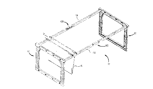
FIG. 1 is a perspective view of the assembled
suspension system of the present invention.
FIGS. 2-7 are isometric views of a first
embodiment of a frame element which is used to form
the frame of the system of FIG. 1, with FIG. 2 being a
front view, FIG. 3 a right side view, FIG. 4 a top
view, FIG. 5 a rear view, FIG. 6 a left side view, and
FIG. 7 a bottom view.
2~ FIGS. 8-11 are isometric views of a corresponding
frame element which is used to join with the frame
element of FIGS. 2-7 to form the frame of the system
of FIG. 1, with FIG. 8 being a front view, FIG. 9 a
right side view, FIG. 10 a rear view, and FIG. il a
left side view.
FIG. 12 is a partial perspective view of a
locking element of one frame element engaging an
aperture of the other frame element for locking
engagement of the frame elements.
~~~1~~2
- 10 -
FIG. 13 is a front view of a second embodiment of
a frame which is made of frame elements which are
different from those of FIGS. 2-11.
FIG. 14 is a cross-sectional view of the
horizontal bracket members of the frame of FIG. 13
taken along lines 14--14 illustrating the frame in
position for forming a suspension frame for letter
size hanging folders.
FIG. 14A is a partial side view illustrating the
registration means which is used to align the frame
elements.
FIG. 15 illustrates the frame of FIG. 14 in
position for forming a suspension frame for legal size
hanging folders.
FIG. 16 is a top view of two rail elements
positioned in adjacent relation with the connecting
bracket positioned alongside.
FIGS. 17-20 are isometric views of the rail
element connecting bracket of FIG. 16, with FIG. 17
being a front view, FIG. 18 a top view, FIG. 19 a back
view and FIG. 20 an end view.
FIG. 21 is a top-view of an alternative
embodiment of the rail connecting bracket in a flat
Preformed position.
FIG. 22 is a side view of another embodiment of a
rail element connecting bracket in combination with
two rail elements in a pivoted position.
FIG. 23 is a perspective view of a compact
Package for storing and shipping the suspension system
of the invention.
DETAILED DESCRIPTION OF THE INVENTION
Referring initially to FIG. 1, there is
illustrated a hanging folder suspension system 10
comprising two identical end frames 12 and a pair of
w ~~~~~iz
substantially identical support rails 14 according to
the invention in a working position for supporting one
or a plurality of hanging file folders 16 thereon.
The support rails 14 are insertably mounted parallel
ta~ each other in a pre-specified spatial relation at
an upper end of the frames at a height enabling the
proper suspension of hanging file folders 16. During
use, the hanging file folders 16 are hung by means of
end hooks 18 which engage the support rails 14, and
can slide along the rails to provide document
organization and access.
Referring now to FIGS. 2-11, each frame 12
comprises two frame elements. One frame element 20,
shown in FIGS. 2-7, has a column member 22 and at
least one substantially horizontal member 24 extending
away from the column member 22. For improved rigidity
of the frame, each frame element advantageously
includes a second horizontal bracket member 26, which
is substantially identical to the first bracket member
24 and disposed below it at the lower end of the
column member 22.
FIGS. 8-11 show a second frame element 30
including a column member 32 and first and second
horizontal bracket members 34, 36 which matingly
engages the horizontal bracket members 24, 26 of the
first frame element 20.
The uppermost end of the column member 22, 32 of
each frame element is provided with rail-positioning
means 40 for mounting the support rails 14. According
to the invention, each rail-positioning means 40
comprises a receiving channel 42 formed in the top
portion of the respective column member 22,.32 at a
height which enables the suspension of the file
folders 16. The receiving channel 42 has a receiving
depth which terminates in a rear wall 44 and is of a
- 12 -
length sufficient to retain one end of a support rail
14 in a substantially horizontal position therein.
Preferably, this depth is about 1 cm. Receiving
g channel 42 also should advantageously provide a
sliding and progressively frictional snug fit with the
end of the support rail 14.
The frame elements 20, 30 are provided with means
for adjustably connecting the horizontal bracket
members 24, 26 of the first frame element 20 to the
horizontal bracket members 34, 36 of the second frame
element 30. The adjustable connection means allows
the column members 22, 32 of the two frame elements to
be positioned in a desired spaced relation, which
corresponds to a predetermined adjustable distance
between the rail positioning means 40. This
adjustable connecting means comprises a plurality of
spaced apertures 50, positioned along the horizontal
bracket members 24, 26 of frame element 20 and a
Plurality of correspondingly spaced locking elements
60, positioned along the horizontal bracket members
34, 36 of the other frame element 30.
According to the invention, the apertures include
a first opening 52 of a substantially circular shape,
and a second opening which has an elongated slot- like
shape. The locking elements 60 comprise first and
second neck portions 62, secured to the horizontal
bracket member and a head portion 64 having at least
one larger dimension than the neck portions 62 and
being integral therewith. The bead portion 64 is
spaced from the respective bracket member 34, 36 by a
length which approximately corresponds to the depth of
the apertures 50 of the other bracket members 24, 26.
Also,, the first opening 52 is dimensioned to receive
both the head and neck portions of the locking
elements 60, while the second opening 54 is smaller
~~l~~z
- 13~ -
than the head portion 64 but larger than the neck
portion 62.
In its working position, the locking elements 60
are adapted to lockingly engage at least two of the
apertures 50, positioned on the respective bracket
members 24, 26. Generally, at least three of the four
apertures shown are engaged by the locking elements
60. The locking elements are placed into the first
openings 52, and the head 64 and neck 62 portions are
slid linearly to engage the neck portions into the
second openings 54 of the apertures 50. The
connecting means thus reduces the degrees of freedom
of the relative motion between the two frame elements
20, 30, thus enabling uncoupling in only one linear
direction.
To provide additional strength of the interlocked
connection of the frame elements 20, 30 and to
increase the rigidity of the frame 10, the horizontal
bracket members 24, 26, 34, 36 each have a
substantially U-shaped cross-section 70 which includes
two flange portions 72, 74 integrally secured at a
substant~.all~y right angle to an elongated wall portion
76. The horizontal bracket members of one frame
element, e.g. 20, have an inner distance between the
flange portions 72, 74, which correspond to width of
the elongated wall portion of the horizontal bracket
members of the other frame element 30. When
assembled, the horizontal bracket members of one frame
element are inserted into the horizontal bracket
members of the other. This connection increases the
rigidity of the frame 12, particularly against
vertically acting forces.
The design of the frame elements 20, 30, in
conjunction with the connecting means provides in a
working position only one degree of freedom in the
- 14 -
relative motion of the engaged bracket members. This
relative motion is constrained to the horizontal
direction and is further restricted by the length of
the apertures 50 and distance between the neck portion
62 of the locking elements 60. During use, this
motion will not exceed the length of the suspending
hooks of the file folders, thus providing the desired
lateral spacing of the support rails 14.
FIGS. 13-16 illustrate another frame 80 composed
of frame elements 82, 84 which are similar to frame
elements 20, 30 with the main difference being the
design of the horizontal bracket connecting means. In
this frame 80, the connecting means include apertures
86 in the shape of an elongated slot. The locking
elements 88 are hooks which are configured to pass
through the slots 86 with the hooks engaging the
bracket at the end of the slot 86 to form a secure
connection.
FIGS. 14 and 15 show two different such locking
connections iaetween the frame elements 82 and 84
adjusted for use of the lhanging folder frame for two
different size file folders ~e.9., letter and legal
size). Also, although these bracket members are
Preferred to be horizontal, it is also possible for
these brackets to have different configurations so
long as at least a portion is substantially horizontal
for engaging the corresponding bracket element of the
cor-=esponding frame element .
In some applications it may be desirable to
further secure the relative position of the column
members. According to one embodiment of the
invention, as shown in FIGS. 14-15, this feature is
achieved by using registration means which comprises a
raised portion or dimple 90, integrally formed on one
of the horizontal bracket members, and one or more
- 15 -
apertures or recesses 92 formed on one horizontal
bracket member of the other frame element. The
recesses 92 are spaced at distance from each other,
corresponding to the desired spacings of the column
members. For example, the registration means can be
used to secure a desired relative spacing between the
rail-positioning means corresponding to the length of
letter-size file folders, as shown in FIG.14 or legal-
size file folders, as shown in FIG. 15.
According to the invention, the frame elements
are advantageously made integrally of a plastic
material. This selection of material allows the
design of frames which are aesthetically pleasing, in
addition to weighing less and being relatively
inexpensive. To increase the structural strength of
the frame, the horizontal bracket members are
positioned at its uppermost and lowermost ends of the
column member. Horizontal reinforcing ribs 94 may be
Provided on each column member to impart additional
strength and rigidity to the frame elements as well as
the entire suspension system.
The assemb3y of tine frames in their working
position involves the selection of the desired spacing
between the rail positioning means of the column
members; aligning the horizontal bracket members;
inserting the locking elements into the apertures; and
sliding the bracket members together to engage the
locking eler~.:nts into the apertures to form the frame.
To complete the entire system, a second frame is
assembled in the same tanner, the rear sides of two
frames.are placed in a facing relationship and the
support rails are connected to the channels of each
frame.
While conventional support rails can be utilized
with the frames of this invention, it is advantageous
- _16 -
to utilize a multi-piece support rail in order to
provide compact storage of the frame in a disassembled
position, which is one of the objectives of the
present invention. Referring now to FIG. 16, one such
rail 14 is shown, having at least two rail elements
14A, 14B and at least one connecting bracket 100. If
desired, however, any number of rail elements can be
used depending upon the total desired length of the
rail. The rail elements are substantially shorter
than the total desired length of the support rail 14
and have first ends 102 and second ends 104. For
convenience, the rail elements may have substantially
the same length. The first ends 102 of the rail
elements are designed to slideably and insertably
engage the rail-positioning means 40 of the frame
elements.
The first end 102 of at least one rail element is
in provided with weakened notch regions 106 allowing
longitudinal adjustability of the hanging folder
suspension system. This adjustability is achieved,
after selecting the desired length of the support
rails anc~ sus~pensior~ system, by breaking off a desired
number of notch regions.
The second ends 104 of the rail elements are
placed within the connecting bracket 100. These ends
have arm portions 108A, 108B which matingly engage to
provide strength to the connection within the bracket.
According to o~.e embodiment of the invention, as
shown in FIGS. 17-20, the connection bracket 100 is
made of a single sheet of material shaped into the
form of a sleeve. To facilitate automated production
of the bracket, the material is bent and then
perforated and crimped on one side wall 110 to form
joints 111A, 111B, illC which retain the sleeve in the
desired arrangement. The other side wall of the
~~0~~1~
- 17 -
bracket 112 is provided with two spaced tabs 114 which
in working position engage apertures 116 which are
formed on the second ends 104 of the rail elements to
provide a locking connection thereof. According to
this embodiment, the second ends 104 of the rail
elements are linearly inserted into the ends of the
connection bracket until the tabs 114 of the bracket
lockingly engage the apertures 116 of the rail
elements.
The side walls 110, 112 of the connecting bracket
100 preferably include ramp portions 118 which
facilitate sliding movement of the hanging file
folders over the connecting bracket in each direction.
BY Providing these ramp portions 118 on each corner of
the bracket, the bracket can be mounted on the rail
end in any position.
FIG. 21 illustrates another embodiment of a
connecting bracket 120. This bracket has a U-shape,
although, for clarity, it is shown in a flat position
prior to being formed into the U shape. The bracket
includes a base portion 124 and two side walls 126A,
126B, each of which is provided with a pair of
apertures 122. According to this embodiment, the
apertures 116 in the second ends 104 of the rail
elements are aligned with the apertures 122 of the
bracket 120 and are connected by the use of rivets,
screws or nuts and bolts. The second ends of the rail
elements can be as disclosed above in FIG. 16 or can
be configured with flat or slightly contoured ends.
The base portion 124 of the connecting bracket is
positioned during use on top of the rail elements, so
that the hanging folders slide over it. As~in the
case of the previous embodiment, to facilitate the
sliding motion of the hanging-folders, the side walls
of the bracket include ramp portions 130 which provide
- 18 -
a gradual connection, allowing sliding motion of the
hanging file folders in either direction without
substantial obstruction.
In FIG. 22, there is illustrated another
embodiment of the rail elements connecting bracket
140. According to this embodiment, a U-shaped bracket
is again used, having a base portion 142 and two side
walls 144, one of which is shown in the FIG. The side
walls 144 include apertures 146 for alignment with the
apertures of the second ends of the rail elements.
These apertures are connected by the use of rivets,
screws or nuts and bolts so that the rail elements can
pivot about that connection paint.
The base portion 142 is positioned during use
beneath the rail elements, so that the hanging folders
do not slide upon it. In addition, the base portion
142 of the bracket is shorter than the side walls 144,
creating a recess adapted to receive the rail
elements, when pivoted. In the working position, the
rail elements are linearly aligned, their second ends
inserted into the U-shaped connecting bracket and
secured to the bracket rotationally at aiistance from
their ends approximately equal to half of the length
of the bracket. Advantageously, for increased
structural rigidity of the support rail, the second
ends of the rail elements have mating profiles, with
one portion of the rail element extending over the
mating portion of the other rail element, as
illustrated above in FIG. 16 to distribute vertical
bending forces over a larger area. When disassembled,
the rail e3enaents, rotate about the pivots, as
illustrated in FIG. 22. The length of the slot
between the side walls of the connecting bracket
determines the maximum angle of folding, as its edge
prevents the rail element from further rotation. As
~~0~~.~2
- 19 -
an example, if the length of the slot corresponds to
half of the width of the rail element, the rail
element can be folded at no more than a right angle
with respect to the bracket.
When disassembled, according to this embodiment
of the support rail, the rail elements and the
connecting bracket can be completely disengaged and
placed in any suitable position with respect to each
other for storage and shipment. The rail can be
folded for convenient storage by applying upward
directed force below the bracket. This causes the two
rotational connections of the bracket with the rail
elements to cause the rail elements to pivot, and the
whole rail to be folded.
When disassembled, the elements of the suspension
system according to the invention fit into a compact
storage box 150, as shown in FIG. 23. The two frames
are stored either in an assembled manner on top of
each other, or disassembled in adjacent relation. One
dimension of the storage box is substantially
determined by the longer of the column member or the
horizontal bracket members. The currently standard
dimensions of these elements are approximately 13".
TYPically, the other dimension of the box is
determined by the length of the support rails,
currently about 27". To reduce the length of the
storage. box, some arrangements position the rails
diagonally.
According to the invention, the support rails are
stared in the box as rail elements. In the embodiment
of FIGS. 16-20, the connecting bracket can be
separately placed into the storage box, with the rail
elements separated. By placing these rail elements
diagonally into the box, a relatively compact box
having dimensions of about 10" by 12" can be achieved.
~I01~~.2
- 20 -
As shown in FIG. 23, the frames can receive the rail
elements for convenient storage.
At the junction points between the column member
22 and the horizontal bracket members 24, 26 of each
frame element are positioned rail-receiving means
which are used to secure, during storage and shipment,
the rail elements in a compact form. A preferred form
of these means is an L-shaped pin which is attached to
the column member to hold the rail elements onto the
frame elements. Other arrangements, such as slots or
grooves for receiving the rail elements can be used,
if desired.
The length of the rail elements can be adjusted
so that the U-shaped bracket may be permanently
affixed to one of the rail elements so that the length
of one rail element with the bracket is essentially
the same as the other rail element. This conserves
space and allows the user to more easily assemble the
rails.
In the embodiments of FIGS. 21 and 22, the
bracket may be stored separately or on the end of one
of the rail elements as described above. For the
embodiment of FIG. 22, it is also possible to provide
the bracket connected to each rail element, when the
elements are capable of rotation. The rail elements
are then rotated for positioning in the box. When
folded in an acute angle (270 degrees is considered a
reasonable choice), the support rails can also be
Positioned diagonally in the box to further minimize
the required storage dimensions.
The dimensions of the storage box create a number
of advantages for the manufacturers and distributors
oil the product, including reduced storage space, the
Possibility to use conventional "Pick'n Pack"
equipment, and ultimately lesser cost for shipping,
r.,
- 21 -
handling and storage. The lesser surface area of the
package of the invention may be calculated as 120
square inches compared to 351 square inches for the
prior art container. Thus, the present invention
provides a reduction in surface area of about 34% for
this example. It is expected that reductions in area
of as much as 40 to 50% can be achieved for certain
sizes. The consumer therefore receives an easy to
assemble versatile office product in a less cumbersome
to handle package storage box.
After receiving the storage box, the user needs
to assemble the two end frames, adjusting the distance
between the raiY positioning means to correspond to
the desired hanging folder width; insert the first
ends of the support rails into the corresponding
channels of the frames; and adjust the length of the
frame to the depth of the file cabinets by breaking
off some of the weakened notch regions at the end
Portions of the rail elements. The procedure requires
no additional tools and is easy to perform.
While the invention has been illustrated and
described in the drawings and the foregoing
description, and alternate embodiments considered, the
same are to be considered as an illustration and not
restrictive in character, it being understood that the
preferred embodiments have been described and all
changes and modifications that are within the spirit
of the invention are desired to be protected.
35