Language selection

Search

Patent 2101802 Summary

Third-party information liability

Some of the information on this Web page has been provided by external sources. The Government of Canada is not responsible for the accuracy, reliability or currency of the information supplied by external sources. Users wishing to rely upon this information should consult directly with the source of the information. Content provided by external sources is not subject to official languages, privacy and accessibility requirements.

Claims and Abstract availability

Any discrepancies in the text and image of the Claims and Abstract are due to differing posting times. Text of the Claims and Abstract are posted:

  • At the time the application is open to public inspection;
  • At the time of issue of the patent (grant).
(12) Patent: (11) CA 2101802
(54) English Title: WAIST BELT WITH SEMI-FLUSH BELT WEATHERSTRIP
(54) French Title: MOULURE DE CEINTURE A CAOUTCHOUC D'ETANCHEITE SEMI-ENCASTRE
Status: Expired and beyond the Period of Reversal
Bibliographic Data
(51) International Patent Classification (IPC):
(72) Inventors :
  • VAUGHAN, ROBERT ALBERT (United States of America)
(73) Owners :
  • COOPER-STANDARD AUTOMOTIVE INC.
(71) Applicants :
  • COOPER-STANDARD AUTOMOTIVE INC. (United States of America)
(74) Agent: MACRAE & CO.
(74) Associate agent:
(45) Issued: 1998-03-31
(22) Filed Date: 1993-08-03
(41) Open to Public Inspection: 1994-05-20
Examination requested: 1994-10-04
Availability of licence: N/A
Dedicated to the Public: N/A
(25) Language of filing: English

Patent Cooperation Treaty (PCT): No

(30) Application Priority Data:
Application No. Country/Territory Date
978,923 (United States of America) 1992-11-19

Abstracts

English Abstract


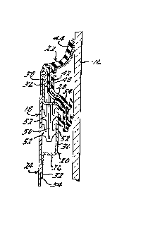
A waist belt for an automotive vehicle has a channel member secured to a
vertically extending door skin. The channel member has vertically open slots. A belt
weatherstrip has a core sheet with legs which extend downwardly into the slots.


French Abstract

Ceinture de caisse pour une portière d'un véhicule automobile comportant un conduit fixé à un côté de la porte se prolongeant verticalement. Le conduit comporte des fentes verticales. Un bourrelet d'étanchéité comprend une feuille de noyau à pattes qui s'insèrent dans les fentes vers le bas.

Claims

Note: Claims are shown in the official language in which they were submitted.


WHAT IS CLAIMED IS:
1. A waist belt construction for an automotive vehicle, said waist belt
construction having:
a vertically extending waist belt flange edge with an elongated horizontally
extending reinforcing channel member secured thereon, said channel
member having a plurality of upwardly open slots therein; and
a belt weatherstrip attached to said flange edge, said weatherstrip having a core
at least partially covered with elastomeric material, said core having a
sheet with legs extending downwardly therefrom, said downwardly
extending legs engaging said channel member by extending into the
upwardly open slots thereof.
2. A waist belt construction as in Claim 1 wherein said downwardly extending
legs carry a plurality of elastomeric retaining ribs.
3. A waist belt construction as in Claim 2 wherein said sheet
carries a plurality of elastomeric sealing ribs.
4. A waist belt construction as in Claim 1 wherein said downwardly extending
legs are held in compression within said reinforcing channel.
5. A waist belt construction as in Claim 1 wherein said downwardly extending
legs and said core sheet hold a wall of said channel in compression therebetween.

6. A waist belt construction as in Claim 1 wherein said downwardly extending
legs have free ends extending below said sheet.
7. A waist belt construction as in Claim 1 wherein the lower edge of said
sheet extend below said downwardly extending legs.
8. A waist belt construction as in Claim 1 wherein said lower edge of said
sheet and the free ends of said downwardly extending legs substantially the same distance
downwardly.

Description

Note: Descriptions are shown in the official language in which they were submitted.


21~18~2
WAIST BELT WIT~ SEMI-~LUSH BELT WEAT~ERSTRIP
BACKGROI~ND OF THE INVENIION
The present invention relates to automotive waist belt constructions. More
particularly, the present invention relates to a waist belt construction including a belt
weatherstrip for an automotive vehicle.
Conventional automotive vehicles have doors with vertically moveable
windowpanes. A belt weatherstrip molding is employed along the lower edge of the
window pane to protect against the weather el.vil onll.ent and to illl~l ove the appearance
of the vehicle. The moveable windowpane is referred to as drop glass, and the upper
metal flange of the outer door panel of the vehicle into which the windowpane drops is
re~erred to as the waist belt of the automobile door. Belt weatherstrips are generally
secured to waist belts by metal clips. However, illJpluv~d belt weatherstrips have been
disc]osed in U.S. Patent No. 4,969,303 November 13, 1990 to ~.mmon~ and in U.S. Patent
No. 5,018,308 May 28, 1991 to Vaughan.
There remains, however, room for i.llplov~lllent in belt weatherstrip
arrangements. Accordingly, the present ill~enlion provides an illl~l uved waist belt having
an outer belt weatherstrip which affords an automotive stylist a means to ~ P- the
amount of black weatherstrip seen at the waist belt. The present invention also affords
an automotive stylist means to ".;..;.";,e the amount of offset between the outer surface
of drop glass and the sheet metal of the outer door panel of a col.vcnliol.a] metal
automot;ve door. This obtains a semi-flush col.sllu.;lion and provides a continuous
condition along the side of the vehicle which is not only aesthetically plea~ing~ but also

ri 2 1 0 1 8 0 2
aids in smoothing the outer surface of the vehicle which can illlplc~.e the aerodynamic
properties of the vehic]e.
Most automotive vehicles employ a lGil~ro~ g bracket attarhed by a pi~ ld
flange a]ong the waist belt area of the automotive door. The present invention employs
a hem flange instead of a pinchweld flange to fasten the panel to its I cillrol lG~ . The
purpose of the leil,ro~celuent is to strengthen the belt opening of the door. In
accordance with the present ill~/elllion, the reillrorcement is shaped to form a box channel
when mated to the inner or outer door panel of the door and upward facing slots are
provided in the box channel. The slots cooperate with duwll~vdldly eYtçnrling legs of a
cooperating belt weatherstrip which extend therein. This construction ..,;.,i..,;,~s the
amount of black weatherstrip pl ~ i~elllt;d to the eye at the waist belt, ~ f S the offset
between drop glass and sheet metal outer surfaces and obtains a serni-flush construction.
Further understanding of the present illvelllioll will be had from the following
rl~ure and claims taken in conjunction with the accn~p~ ring dldwing;~.
SUMMARY OF TEIE INVE~lllON
A waist belt collslluclion for an automobile has~
a vertically ~Yt~nrling waist belt ~ange edge with an elnne~ted hnri7r)nt~l1y
f~ytf~n~1ing Itil~l~lg channel meTnher secured thereon, said channel mpmher having a
plurality of upwardly open slots therein; and -
a belt weatherstrip att~rllPd to said flange edge, said weatherstrip having a core
at least partially covered with elq~ilo.../ - ;~ m~teriql, said core having a sheet with legs
~Ytçnrline duwl~wardly ther~ull" said du..~l~.dldly t~ e legs engqeine said channel
m~mbPr by eYten~lin~ into the upwardly open slots thereof.

2101802
BRIEF DESCRIrl~ON OF T~IE DRAWINGS
Figure 1 is a side elevation, broken away, of an automotive vehicle having a
p.Gre.,~ d embodiment of a waist belt construction of the present invention.
Figure 2 is a cross-sectional -view taken along line 2-2 in Figure 1 and showing a
plerellcd embodiment of the present invention.
Figure 3 is a cross-sectinn~l -view analogous to Figure 2 but showing a pAor art
waist belt construction.
Figure 4 is a rear elevational view of the prerelled embodiment of Figures 1 and
2.
Figure S is an exploded, perspective view, broken away, showing the ~lef~ d
embodiment of Figures 1, 2 and 4.
Figure 6 is a perspective view, broken away, showing an Al~ ..I;ve belt
weatherstrip of the present i"vellliol~.
Figure 7 is a perspective view, broken away, showing another ~lle~ ive belt
weatherstrip of the present illvt;lllioll.
Figure 8 is a sec~inn~l view showing a waist belt construction including the belt
weatherstrip of Figure 6 with the section being taken through a leg of the core of the belt
we~thprstrir~
Figure 9 is a seetinn~l view of the waist belt construction of Figure 8 taken
through the core thereof.

- 2101802
DESCRIPTION OF TEIE INVEN~ION
Now referring to Figure 1, a preferred embodiment of a waist belt co~ uclion
of the present invention is inrlir.ated generally by the numeral 10 and is shown on an
automotive vehicle 12. Waist belt construction 10 is located on door 14 of ~ululllolive
vehicle 12 along the lower edge of window pane 16. Waist belt consll uclion 10 generally
c-,.,.p.;~es a waist belt flange 18 with a reillrul~,g channel ~ mbe~ 20 having a belt
weatherstrip 22 secured thereon in the manner descrihed herein.
Waist belt flange 18 is the upper flange edge of outer door panel 24 and extends
generally vertically. For increased strength, a channel member 20 extends hnri7.nnt~l1y
along waist belt flange 18. Channel member 20 has legs 26 and 28 joined by web 30.
Leg 26 has skirt 32 secured to waist belt flange 18, for c ~e, by adhesive 34. Leg 28
has skirt 36 which is secured to the upper edge portion of waist belt flange 18 by hem
flange 38 which is the reversely bent upper edge portion of waist belt flange 18. It will
be well appreciated by those skilled in the art that this method of ~tt~( hing chaDnel
m~mh-o.r 20 provides an upper edge portion of waist belt flange 28 which is free of weld
spots or other disco~ uilies which would detract from the appealdnce of the outer door
panel, thus pro~ding a smooth outer surface and a cnntinuouC cnn~litinn along the waist
belt.
As is best shown in Figure 5, a plurality of spaced apart ap~. lul ~ s 40 are provided
in leg 28. Of course, a~ellule 40 can extend partially into skirt 36 and web 30 as shown
in Figure 5.
Belt weatherstrip 22 has a metal core 42 which carries }ip 44 with flocking or other
low friction surface for cont~ctin~e window pane 16. Core 42 has a main body portion 48

2101802
with a p]urality of horizontally spaced apart downstanding legs S0. Dow.,~l;.r-riin~ legs
50 can be stamped from main body portion 48 in a con~ ional press.
As is shown in Figure 2, belt weatherstrip 22 is secured to box channel 20 and
waist belt flange 18 in the following manner. The plurality of dt w~lcl~n~ legs 50
extend through .,oll~,s~onding plurality of upwardly facing apertures 40 and box channel
20. Gripping ribs 52 are held in cûlll~ ion between box channel 20 and waist belt
flange 18 pressing against the inwardly facing surfaces of waist belt flange 18 and web 30
of box channel 20. ~rlAition~l gripping ribs 54 are carried on the lower edge portion of
main body portion 48 of core 42 and press against the outwardly facing side of web 30.
Figure 3 shows a c~.vellliollal prior art waist belt cull~llu~ . As is well
illustrated by c~ -..p~. ;..g Figure 3 with Figure 2, the waist belt consl~ uclio" of the present
illvellLiol offers a sllu~lule which is relatively thin when c~ aled to the method of
~;oll;,ll u-;lion illustrated in Figure 3 which requires that a part "A" of the belt weatherstrip
extends over spot welds "B" to cover them from casual view. Thus, the present il.~ io,
not only has the advantage of a thin profile but also in ~ulf-f l~;l.e only a thin strip of
elaslolue~ic m~tçn~l to casual -view.
Now lere.li~lg to Figures 6, 8 and 9, an ~ls-f...~l~ve embodiment of a belt
weatherstrip for use in accordance with the present i~ iOll is shown and indicted
generally by the nu_eral 100. Belt weatherstrip 100 has a core 142 with du..l.~.dldly
eYtçn~lin~ il-se.lioll tabs 150. Dc,..~lwdldly f~rtf.nrlin~ s.,llion tabs 150 function in a
manner analogous to tabs 50 of belt weatherstrip 22. Belt ~._a~ 100 is well
adapted for use in waist belt col~sllu~,lion as illustrated in Figures 8 and 9, with Figure
8 being a sectir.n~l -view taken through the dow..~ tline leg 150 of belt weatherstrip 100

2~1802
and Figure 9 being a section~l view taken through the portion of core 142 which does not
have a leg 150 stamped therefrom.
Now lefc~ g to Figure 7, still another ~ltern~tive embodiment of a belt
weatherstrip of the present invention is shown and inrlir~ted by the numeral 200. Belt
weatherstrip 22 has a core 242 with dowllwaldly ,~ g insertion tabs 250. Tabs 250
function in a manner analogous to tabs 50 and 150 but are stamped from core 242 so as ;
to extend below the bottom edge thereof. ~ -
While the above description sets forth ~,lefclled embotlim~ntc of the present ~ ;
,nlioll, it is to be ap~lec;ated that the invention is subject to mo-lifi~atir-n, variation
and change without depallil,g from the proper scope and fair .,.~I.;.,g of the
acco,ll~al,yillg claims. ~ ~ ~
.' ' '
, ~ ' ' ;'
~,~'''' ~ ." .''' ''',' '

Representative Drawing
A single figure which represents the drawing illustrating the invention.
Administrative Status

2024-08-01:As part of the Next Generation Patents (NGP) transition, the Canadian Patents Database (CPD) now contains a more detailed Event History, which replicates the Event Log of our new back-office solution.

Please note that "Inactive:" events refers to events no longer in use in our new back-office solution.

For a clearer understanding of the status of the application/patent presented on this page, the site Disclaimer , as well as the definitions for Patent , Event History , Maintenance Fee  and Payment History  should be consulted.

Event History

Description Date
Inactive: IPC expired 2016-01-01
Time Limit for Reversal Expired 2009-08-03
Letter Sent 2008-08-04
Letter Sent 2004-12-15
Grant by Issuance 1998-03-31
Inactive: Final fee received 1997-11-14
Pre-grant 1997-11-14
Notice of Allowance is Issued 1997-07-07
4 1997-07-07
Letter Sent 1997-07-07
Inactive: Status info is complete as of Log entry date 1997-07-02
Inactive: Application prosecuted on TS as of Log entry date 1997-07-02
Inactive: IPC removed 1997-06-19
Inactive: First IPC assigned 1997-06-19
Inactive: IPC assigned 1997-06-19
Inactive: Approved for allowance (AFA) 1997-06-06
Request for Examination Requirements Determined Compliant 1994-10-04
All Requirements for Examination Determined Compliant 1994-10-04
Application Published (Open to Public Inspection) 1994-05-20

Abandonment History

There is no abandonment history.

Maintenance Fee

The last payment was received on 1997-06-30

Note : If the full payment has not been received on or before the date indicated, a further fee may be required which may be one of the following

  • the reinstatement fee;
  • the late payment fee; or
  • additional fee to reverse deemed expiry.

Patent fees are adjusted on the 1st of January every year. The amounts above are the current amounts if received by December 31 of the current year.
Please refer to the CIPO Patent Fees web page to see all current fee amounts.

Fee History

Fee Type Anniversary Year Due Date Paid Date
MF (application, 4th anniv.) - standard 04 1997-08-04 1997-06-30
Final fee - standard 1997-11-14
MF (patent, 5th anniv.) - standard 1998-08-03 1998-06-26
MF (patent, 6th anniv.) - standard 1999-08-03 1999-07-02
MF (patent, 7th anniv.) - standard 2000-08-03 2000-07-04
MF (patent, 8th anniv.) - standard 2001-08-03 2001-06-20
MF (patent, 9th anniv.) - standard 2002-08-05 2002-06-26
MF (patent, 10th anniv.) - standard 2003-08-04 2003-07-04
MF (patent, 11th anniv.) - standard 2004-08-03 2004-08-03
Registration of a document 2004-11-23
MF (patent, 12th anniv.) - standard 2005-08-03 2005-07-08
MF (patent, 13th anniv.) - standard 2006-08-03 2006-08-01
MF (patent, 14th anniv.) - standard 2007-08-03 2007-07-19
Owners on Record

Note: Records showing the ownership history in alphabetical order.

Current Owners on Record
COOPER-STANDARD AUTOMOTIVE INC.
Past Owners on Record
ROBERT ALBERT VAUGHAN
Past Owners that do not appear in the "Owners on Record" listing will appear in other documentation within the application.
Documents

To view selected files, please enter reCAPTCHA code :


To view images, click a link in the Document Description column (Temporarily unavailable). To download the documents, select one or more checkboxes in the first column and then click the "Download Selected in PDF format (Zip Archive)" or the "Download Selected as Single PDF" button.

List of published and non-published patent-specific documents on the CPD .

If you have any difficulty accessing content, you can call the Client Service Centre at 1-866-997-1936 or send them an e-mail at CIPO Client Service Centre.

({010=All Documents, 020=As Filed, 030=As Open to Public Inspection, 040=At Issuance, 050=Examination, 060=Incoming Correspondence, 070=Miscellaneous, 080=Outgoing Correspondence, 090=Payment})


Document
Description 
Date
(yyyy-mm-dd) 
Number of pages   Size of Image (KB) 
Abstract 1995-04-13 1 41
Claims 1995-04-13 2 100
Drawings 1995-04-13 3 179
Description 1995-04-13 6 323
Claims 1997-04-15 2 39
Representative drawing 1998-03-08 1 7
Commissioner's Notice - Application Found Allowable 1997-07-06 1 164
Maintenance Fee Notice 2008-09-14 1 171
Correspondence 1997-11-13 1 34
Fees 2004-08-02 2 66
Fees 2006-07-31 2 60
Fees 1996-06-26 1 62
Fees 1995-06-28 1 69
Prosecution correspondence 1994-10-03 1 38
Examiner Requisition 1996-09-26 1 49
Prosecution correspondence 1997-03-26 1 35
PCT Correspondence 1993-10-04 1 24
Courtesy - Office Letter 1994-10-18 1 67