Language selection

Search

Patent 2102261 Summary

Third-party information liability

Some of the information on this Web page has been provided by external sources. The Government of Canada is not responsible for the accuracy, reliability or currency of the information supplied by external sources. Users wishing to rely upon this information should consult directly with the source of the information. Content provided by external sources is not subject to official languages, privacy and accessibility requirements.

Claims and Abstract availability

Any discrepancies in the text and image of the Claims and Abstract are due to differing posting times. Text of the Claims and Abstract are posted:

  • At the time the application is open to public inspection;
  • At the time of issue of the patent (grant).
(12) Patent Application: (11) CA 2102261
(54) English Title: HOLLOW ROTARY DRUM PROCESSOR
(54) French Title: TAMBOUR DE DEVELOPPEMENT
Status: Deemed Abandoned and Beyond the Period of Reinstatement - Pending Response to Notice of Disregarded Communication
Bibliographic Data
(51) International Patent Classification (IPC):
  • G03D 03/06 (2006.01)
  • G03D 13/00 (2006.01)
  • G03D 13/04 (2006.01)
(72) Inventors :
  • FYSON, JOHN RICHARD (United Kingdom)
(73) Owners :
  • EASTMAN KODAK COMPANY
(71) Applicants :
  • EASTMAN KODAK COMPANY (United States of America)
(74) Agent: GOWLING WLG (CANADA) LLP
(74) Associate agent:
(45) Issued:
(22) Filed Date: 1993-11-02
(41) Open to Public Inspection: 1994-06-19
Examination requested: 1999-12-21
Availability of licence: N/A
Dedicated to the Public: N/A
(25) Language of filing: English

Patent Cooperation Treaty (PCT): No

(30) Application Priority Data:
Application No. Country/Territory Date
9226483.7 (United Kingdom) 1992-12-18

Abstracts

English Abstract


ABSTRACT OF THE DISCLOSURE
This specification discloses a hollow rotary drum
processor for bringing a pliable sheet of material,
such as photographic paper, into contact with a
processing liquid, the drum processor having an
interior which is partly filled with liquid and
which is caused or allowed to be uniformly heated.
The interior of the drum processor is closed so
that the liquid is entrapped therein and the energy
to be transmitted by or through it is imparted to
it within the drum processor. The apparatus may
include heating means within the drum processor,
the heating means being operable to heat the liquid
so that the energy is heat energy.


Claims

Note: Claims are shown in the official language in which they were submitted.

- 8 -
CLAIMS
1. A hollow rotary drum processor which has an
interior which is partly filled with liquid and which
is caused or allowed to be uniformly heated by
transmission of energy to it by or through the liquid
as it rotates, wherein the interior of the drum
processor is closed so that the liquid is entrapped
therein and the energy to be transmitted by or
through it is imparted to it within the drum
processor.
2. A hollow rotary drum processor according to claim
1, including heating means within the drum processor,
the heating means being operable to heat the liquid
so that the energy is heat energy.
3. A hollow rotary drum processor according to claim
2, wherein the heating means is an electrical
immersion heating element which is mounted within
the drum processor so that it is always immersed in
the liquid.
4. A hollow rotary drum processor according to claim
2 wherein the heating means comprise a pair of spaced
electrodes and means operable to cause current to
flow between them through the liquid within the drum
processor.
5. A hollow rotary drum processor according to claim
1 or claim 4, including an electrode which is mounted
within the drum processor so as to be electrically

- 9 -
insulated from the drum processor which serves as
another electrode, and means are provided for
applying an electrical potential between the two
electrodes so that current flows between them through
the liquid and the energy is electrical.
6. A hollow rotary drum processor according to any
one of claims 3 to 5, wherein the electrical
immersion heating element or the pair of electrodes
is connected to an external source of electric power
through a rotary transformer outside the drum
processor, the rotary transformer comprising a rotary
winding carried by an axle of the drum processor and
a stationary winding mounted in structure on which
the drum processor is journalled, the rotary winding
being connected to the heating element or to the pair
of electrodes through the axle by which it is
carried.
7. A hollow rotary drum processor according to any
one of claims 1 to 4 and 6 when appended to claim 2,
including heat sensing means operable to limit the
amount of heat emitted by the heating means.
8. A hollow rotary drum processor according to claim
7 wherein the heat sensing means is within the drum
processor and is adapted to operate directly in
conjunction with the heating means.
9. A hollow rotary drum processor according to claim
6, including heat sensing means operable to sense
thermal conditions outside the drum processor related
to the state of heating of the drum processor, said
heat sensing means being operable to control the
heating of the drum processor by controlling the

- 10 -
connection of the external source of power through
the rotary transformer.
10. A hollow rotary drum processor according to any
one of claims 1 to 9, wherein the internal surface of
the drum processor is configured so as to effect
agitation of the liquid within the drum processor as
it rotates.
11. A hollow rotary drum processor substantially as
described hereinbefore with reference to and as
illustrated in the accompanying diagram.

Description

Note: Descriptions are shown in the official language in which they were submitted.


~2~.$1
A HOLLOW ROTARY DR _ PROCESSOR
DESCRIPTION
This invention relates to a hollow rotary drum
proce~sor for bringinq a pliable sheet of material,
such as photographic paper, into contact with
processing liquid, the drum processor having an
interior which is partly filled with liquid and which
is caused or allowed to be uniformly heated.
Up to now, hollow rotary drum processors have been
heated by pumping hot water into and out of the drum
as the drum is rotated. The hot wate~ may be pumped
into the drum and withdrawn from the drum at one end
through a pair of co-axial pipes which are formed in
a hub of the dr~m at one end. In another arrangement
- 20 the hot water may be pumped into the drum through a
tubular hub at one end, through and out of the drum
at another end via another tubular hub. In ~oth
cases a reservoir of hot water must be pro~ided as
must a pump. Also there must be provision for sealing
against leakage of liquid at the interface between
the tubular hub or hubs of the drum and the static
conduits leading to the pump and the reservoir.
According to this invention there is provided a
hollow rotary drum processor which has an interior
which is partly filled with liquid and which is
caused or allowed to be uniformly heated by
tran6mission o energy to it by or through the liquid
as it rotates, wherein the interior of the drum
processor is closed so that the liquid is entrapped

2 6 1
-- 2 --
therein and the energy to be transmitted by or
through it i8 imparted to it within the drum
processor.
S The energy may be heat energyI there being heating
means within the dr~n processor operable to heat the
liquid.
The heating means may comprise an electrical
immersion heating element mounted within the drum
processor so that it is always immersed in the liquid
in the drum processor.
The heating means may comprise a pair of spaced
electrodes and means operable to cause current to
flow between them through the liquid within the drum
processor~
In an alternative embodiment of the invention, an
electrode may be mounted within the drum processor so
as to be electrically insulated from the drum
processor which ~serves as another electrode, and
means may be provided ~for applying an electrical
potential between the two electrodes so that current
flows between them through the liquid and the enerqy
~' ~ is electrical. ;~
Conveniently the electrical immersion heating element
or the pair of electrodes is con~ected to an external
source of electric power through a rotary transformer
outside the drum processor,~ the rotary transformer
comprising a rotary~winding carried by an axle of the
drum processor and a stationary winding mounted in
~` structure on which,the drum processor is journalled,
the rotary winding bei~g connected to the' heating
:~ :
~ ~ ,

~1~2~6JL
- 3 -
element or to the pair of electrbdes through the axle
by which it is carried.
There may be heat sensing means operable to limit the
amount of heat emitted by the heating means, and the
heat sensing means may be within the drum processor
and adapted to operate directly in con~unction with
the heating means. Alternatively there may be heat
sensing means operable to sense thermal conditions
outside the drum processor related to the state of
heatiny of the drum processor, the heat sensing means
being operable to control the heating of the drum
processor by controlli.ng the connection of the
external source of power through the rotary
lS transformer.
The internal surface of the drum processor may be
configured so as to e~fect agitation of the liquid
;~ within the drum processor as it rotates.
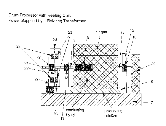
One embodLment of this invention is described now by
way of example~ with reference to the accompanying
diagrammatic illustration of rotary drum processor
apparatus.
A cylindrical drum processor 10 is supported for
rotation about i~s axis between a pair of upright
bearing supports 11 and 12 by having an axle 13,14 at
either end journalled in a respective bearing 15,16
mounted in a respective one of the bearing supports
11 and 12. The bearing supports 11 and 12 are mounted
on base structure 17. The-bottom part of the drum
:: ~
processor 10 is immersed~in processing solution in an
open topped bath~l8 placed on the base structure 17
between the bearing supports 11 and 12. An exposed

21~2~1
-- 4 --
photographic print to be proc~3sed is lald on the
external surface of th~ drum.
The drum processor 10 is hollow and its lnterior is
closed in the sense of being liquid tight. It is
partly filled, being more than half filled with a
heat conducting liquid such as water or silicon
oil.
The internal cylindrical surface of the drum
processor 10 is patterned in order to agitate the
liquid within the drum processor 10 as the latter
rotates.
An electrical immersion heater 19 of the type
commonly used to heat fish tanks, is mounted in the
drum processor 10 and suspended within the interior
of the drum processor 10, at or ad~acant to th~ axis
of the drum processor 10 so that it is always
immersed in the liquid in the drum processor 10. The
heater 19 has a built-in thermostat which is set to
control opera~ion of the heater 19 so as to maintain
the required process temperature. The electrical
leads 21 and 22 of the heater 19 are led through
appropriate conduits formed in the axle 13 and are
connected to respective terminals of a rotary winding
23 of a rotary transformer 24, the rotary winding 23
being mounted in a soft iron core 25 which is fixed
to the axle 13 on the opposite side of the bearing
support 11 from the drum processor 10, so as to
rotate therewith. The rotary winding 23 is located in
an annular groove in a vertical face of the soft iron
core 25 remote from the drum processor 10. The leads
21 and 22 are led through appropriate liquid seals
which seal against leakage of liquid from within the

2 ~ ~ ~
.. s
drum proces~or 10 through the conduits ln the axle
13.
It is safer to use silicon oil rather than water
because it is a poor conductor of electricity. The
drum processor 10 is not completely filled with the
heat conducting liquid in o:rder to allow for
expansion of the liquid and to avoid any risk of
bursting of the drum processor 10. A blow out cap
could be fitted to cater for excessive expansion of
liquid due to overheating which might otherwise cause
the drum to burs~.
The axle 13 pro~ects through the rotary soft iron
core 25 and is journalled i.n another bearing 25 which
is mounted in another soft iron core 27 which in turn
is mounted on the base structure 17. There is as
small a gap as is possible between the ~uxtaposed
faces of the two soft iron cores 25 and 27 which are
bo~h vertical. The stationary winding 28 of the
rotary ~ransformer 24 is located in an annular groove
formed in the vertical face of the soft iron core 27
that is close to the soft iron core 25, and its
terminals are for connection to a suitable AC power
supply. The use of soft iron cores enables mains
electricity to be used wi.th little power loss.
When the rotary drum processor apparatus is to be
used, the stationary winding 28 is connected to the
AC power supply and the drum processor 10 is rotated
about its axis by a motor 29 which drives the axle
14. A voltage is induced in tAe rotary winding 23 by
the action of the rotary transformer 24 and that
voltage is applied to the heater 19 via the leads 21
and 22. As a result the liquid in the drum processor

~1~22~3~
10 iq heated up, as is the drum processor lO it~elf
by conduction and convection of heat through the
liquid. The rotation of the drum processor lO cause~
the liquid to be stirred and that is supplemented by
the agitation of the liquid induced by the patterned
internal surface of the drum processor lO. That leads
to the drum processor lO being heated uniformly. When
the required state of ~hermal equilibrium has been
reached by the action of the thermostat on the heater
19, the apparatus is ready for processing to begin.
Instead of using the thermostat that is built into
the heater l9, as described, a separate heat sensing
device, which may be a thermostat or a bi-metallic
device, may be immersed in the liquid separately from
the heater 19 and arranged to control operation of
the heater 19 to maintain the required temperature of
the liquid. Alternatively a heat sensor which is in
sliding contact with the external surface of the drum
processor or which is immersed in the processing
solution in the bath 18 may be provided. Such an
external heat sensor may be arranged to control the
supply of power to the stationary winding 28 in order
to maintain the temperature of the drum processor lO
or of the processing solution in the bath 18 at the
required level.
Instead of heating the drum processor lO indirectly
by heating the liquid in it, it is possible to heat
the drum processor lO by passing current directly
through the liquid between two electrodes (for
example between one electrode immersed in the liquid
and the drum which would be used as the other
electrode), the electrodes being connected to
respective ones of the terminals of the rotary

2 ~ ~
7 --
winding of the rotary transformer. The electrical
potent:Lal supplied from the rotary transformer wollld
need to be low.

Representative Drawing
A single figure which represents the drawing illustrating the invention.
Administrative Status

2024-08-01:As part of the Next Generation Patents (NGP) transition, the Canadian Patents Database (CPD) now contains a more detailed Event History, which replicates the Event Log of our new back-office solution.

Please note that "Inactive:" events refers to events no longer in use in our new back-office solution.

For a clearer understanding of the status of the application/patent presented on this page, the site Disclaimer , as well as the definitions for Patent , Event History , Maintenance Fee  and Payment History  should be consulted.

Event History

Description Date
Inactive: IPC from MCD 2006-03-11
Application Not Reinstated by Deadline 2004-04-05
Inactive: Dead - No reply to s.30(2) Rules requisition 2004-04-05
Deemed Abandoned - Failure to Respond to Maintenance Fee Notice 2003-11-03
Inactive: Abandoned - No reply to s.30(2) Rules requisition 2003-04-04
Inactive: S.30(2) Rules - Examiner requisition 2002-12-04
Amendment Received - Voluntary Amendment 2000-04-03
Letter Sent 2000-01-12
Inactive: Status info is complete as of Log entry date 2000-01-12
Inactive: Application prosecuted on TS as of Log entry date 2000-01-12
All Requirements for Examination Determined Compliant 1999-12-21
Request for Examination Requirements Determined Compliant 1999-12-21
Application Published (Open to Public Inspection) 1994-06-19

Abandonment History

Abandonment Date Reason Reinstatement Date
2003-11-03

Maintenance Fee

The last payment was received on 2002-10-11

Note : If the full payment has not been received on or before the date indicated, a further fee may be required which may be one of the following

  • the reinstatement fee;
  • the late payment fee; or
  • additional fee to reverse deemed expiry.

Patent fees are adjusted on the 1st of January every year. The amounts above are the current amounts if received by December 31 of the current year.
Please refer to the CIPO Patent Fees web page to see all current fee amounts.

Fee History

Fee Type Anniversary Year Due Date Paid Date
MF (application, 4th anniv.) - standard 04 1997-11-03 1997-09-19
MF (application, 5th anniv.) - standard 05 1998-11-02 1998-09-25
MF (application, 6th anniv.) - standard 06 1999-11-02 1999-09-17
Request for examination - standard 1999-12-21
MF (application, 7th anniv.) - standard 07 2000-11-02 2000-10-03
MF (application, 8th anniv.) - standard 08 2001-11-02 2001-10-12
MF (application, 9th anniv.) - standard 09 2002-11-04 2002-10-11
Owners on Record

Note: Records showing the ownership history in alphabetical order.

Current Owners on Record
EASTMAN KODAK COMPANY
Past Owners on Record
JOHN RICHARD FYSON
Past Owners that do not appear in the "Owners on Record" listing will appear in other documentation within the application.
Documents

To view selected files, please enter reCAPTCHA code :


To view images, click a link in the Document Description column (Temporarily unavailable). To download the documents, select one or more checkboxes in the first column and then click the "Download Selected in PDF format (Zip Archive)" or the "Download Selected as Single PDF" button.

List of published and non-published patent-specific documents on the CPD .

If you have any difficulty accessing content, you can call the Client Service Centre at 1-866-997-1936 or send them an e-mail at CIPO Client Service Centre.

({010=All Documents, 020=As Filed, 030=As Open to Public Inspection, 040=At Issuance, 050=Examination, 060=Incoming Correspondence, 070=Miscellaneous, 080=Outgoing Correspondence, 090=Payment})


Document
Description 
Date
(yyyy-mm-dd) 
Number of pages   Size of Image (KB) 
Representative drawing 1998-08-18 1 40
Claims 1995-04-13 3 152
Drawings 1995-04-13 1 84
Abstract 1995-04-13 1 38
Description 1995-04-13 7 507
Claims 2000-04-02 3 92
Acknowledgement of Request for Examination 2000-01-11 1 180
Courtesy - Abandonment Letter (R30(2)) 2003-06-15 1 165
Courtesy - Abandonment Letter (Maintenance Fee) 2003-12-28 1 177
Fees 1996-09-23 1 96
Fees 1995-10-19 1 64