Note: Descriptions are shown in the official language in which they were submitted.
CA 02102343 1999-10-O1
Process and Installation for the Separation
of Solid-Liauid-Mixtures
The present invention relates to processes for the
separation, preferably filtration, of liquids and
solids from liquid-solid-mixtures, in particular from a
mineral solid-liquid-suspension, preferably an ore or
coal suspension or sludge of contaminated earth, the
process space being submitted to overpressure, as well
as to an installation for carrying out the process,
consisting of a collector container for liquid-solid-
mixture, in particular liquid-solid-suspension, a
pressure filter, a discharge system and container for
condensate and solid matter.
Such processes and installations have already
successfully been employed in the field of mineral
processing for the treatment of ore and coal
concentrates. A special variant of a pressure filter
suitable therefor is described in German Patent
Publication No. DE-2,947,329 (Stahl) published on
May 27, 1981. This does, however, not satisfy the
requirements for dehumidification of ore or coal
concentrates and for an application for the
decontamination of contaminated earth, respectively.
Thus the present invention proposes that the
separation, in particular filtration, of solids and
liquids from solid-liquid-mixtures, in particular from
mineral solid-liquid-suspensions takes place, in
addition to the application of overpressure, under
elevated temperature, for instance 40°C to 300°C,
conveniently 60°C to 200°C, preferably about 150°C.
The elevated temperature primarily reduces the
viscosity of the liquid to be expelled, which makes it
easier to expel the liquid in particular in case of
pressure filtration, resulting from very low residual
- 1 -
CA 02102343 1999-10-O1
moisture values. According to the invention the
elevated temperature may be generated by means of
vapour, in particular water vapour, for instance at
110°C to 200°C, advantageously about 150°C. For this
purpose, according to the invention the pressure filter
communicates with a vapour source.
By using vapour, in particular water vapour, it is
possible to obtain very low contents of residual
moisture in ore and coal concentrates, which are not
obtainable with air as the filtration medium.
Furthermore it is also possible to thereby separate
dangerous substances, as for instance trinitrotoluene
(TNT) from contaminated earths, which furthermore
dissolve
- la -
in vapour and condensate, respectively.
In an embodiment of the process according to the invention the temperature
for the separation or filtration is generated in the whole process space by
means of vapour, in particular water vapour. Thus the known pressure
filters may practically be employed.
A further advantageous modificiation of the process according to the
present invention is characterised in that the overpressure for the
separation or filtration is generated by means of vapour, in particular
water vapour, in a space separ<~ted from the rest of the process space.
Although it is true that separation of the filtration space is additionally
necessary here, on the other hard, there is considerable saving of vapour,
and t;he suppl-ementary aggregates housed in the pressure filter container
are easier to handle. With a type of process like this only the filter has
to be adapted to the elevated temperatures.
Further embodiments of the invention are characterised in that the vapour
is saturated vapour and in that the vapour is overheated vapour,
respectively. A choice of the ~;uitable type of process has to be made in
accordance with the respective requirements as to the separation or
filtration of the mixture, in particular depending on the material to be
filtered.
According to an advantageous development of the invention the condensed
vapour is discharged together with the liquid to be expelled, for instance
water, TNT. Separation of the condensed vapour from the liquid to be
expelled may be avoided by appropriate choice of the vapour pressure
medium, which is how further elaborate separation steps may be dispensed
with.
In a further preferable embodiment of the invention, the solid matter
heated by the vapour and separated from the liquid, for instance the ore or
coal concentrate and decontaminated earth, respectively, is separately
submitted to further processing.
A further embodiment of the process according to the invention is
- 2 -
characterised in that the temperature for filtration is generated by
compressed air heated to, for instance 40°C to 300°C,
conveniently 60°C to
200°C, preferably about 150°C. The compressed air necessary for
generating
pressure or compressed air being available from another process, in
particular during operation, may for instance be employed in a simple way
here.
According to the present invention the elevated temperature in the whole
process space may be generated by heated compressed air. Thus the known
pressure filters may practically be taken over. According to a further
embodiment of the invention the elevated temperature may also be generated
by heated compressed air in a space separated from the rest of the process
space. By direct impingement on the filter cake the energy losses in the
pressure chamber may largely be reduced.
A further embodiment according to the invention is characterised in that
the ~~olid-liquid-mixture or solid-liquid-suspension is supplied to the
filter at an elevated temperature, for instance 40°C to 300°C,
conveniently
60°C to 200°C, preferably about .30°C, it being possible
to addtionally heat
the mixture or suspension before it enters the filter. By this type of
process, a considerably more favourable separation or filtration and thus
considerably lower residual moisture values may be obtained without
substantially modifying the pressure filter.
According to the invention economical operation may be achieved in
particular if the air pressure in the container or chamber space of the
filter is controlled in dependance on the vapour pressure. It may, however,
possibly be more favourable for the vapour pressure to be controlled in
dependance on the air pressure in the container and chamber space of the
filter, respectively. According to the invention the effect of separation
or filtration may be particularly raised if, apart from the application of
overpressure at elevated temperature, the solid-liquid-mixture, in
particular solid-liquid-suspension, to be separated, in particular to be
filtrated, is subjected to a movement in addition to the usual movement of
separation, in particular filtration in the filter, in particular in the
filter trough or the like. Then undesired sedimenation and too rapid
obstruction of the filter elements or filter or sieve openings,
- 3 -
''~ ~~'~~.~
respectively, is prevented. This effect in combination with higher working
pressure and elevated working temperature results in particularly
progressive separation or filtration effects and high separation or
filtration performance, respeci~ively, at favourably low expenditure of
energy.
An installation according to the invention for carrying out the process
according to the invention is characterised in that the pressure filter
communicates with a source for heated medium. According to an embodiment of
the invention, this source is a vapour source.
If, according to a further modification of the invention, the container,
for =instance the chamber, of i:he pressure filter communicates with the
vapour source, the whole process space may be filled with vapour in a
particularly easy way.
However, according to the invention the vapour source may communicate with
a separate vapour dome at the interior of the container of the pressure
filter. Thus a special space for vapour pressure filtration may
deliberately be separated from the rest of the process space. Thus no
special type of the materials for the other aggregates situated in the
container of the pressure filter (control head, snap-blow valve, drive,
controlling equipment, measuring probes, electric lines) is necessary.
A favourabledevelopment of the inventionis characterisedin that
the
vapour domecommunicates with the filtertrough of the rotary filter
(rotary or drum filter).. In this way the vapourrequired
disk for
filtration ilter surface,particular
may be in to
fed to
the region
of the
f
the so-calleddehumidification region, targeted way,
in a thus minimizing
the 1 oss
of vapour
and energy.
If subsequently, according to i:he invention, the vapour dome is tightly
connected to the discharge opening of the pressure filter container, the
dome including the material di~~charge and the conveyance system, further
loss of vapour and energy and consequently heating up of the rest of the
process space may be avoided. When using dangerous or toxic substances,
these may also be separated from the rest of the process space and
- 4 -
discharged (disposed of) in a controlled manner.
According to a further favourable embodiment of the invention the source of
heated medium is a source of heated compressed air. According to the
invention this may either communicate with the chamber of the pressure
filter or with a separate dome connected to the filter trough of the rotary
filter, in the interior of the container of the pressure filter.
According to a further embodiment of the invention the source for heated
medium is a supply of hot solid-liquid-mixture or solid-liquid-suspension.
An advantageous embodiment of the invention is characterised in that the
vapour dome is provided with outlets on both sides of the filter disk for
the vapour and the heated compressed air, respectively. By this
construction, the vapour and the heated compressed air, respectively, may
be directly applied to the filter cake on the filter disk.
According to a further favourable modification of the invention, the vapour
dome communicates with the pressure space via at least one valve flap.
Here the flap may be opened towards the pressure space or the vapour space,
it also being possible to provide a combination of two flaps.
Particularly advantageously the at least one flap opens at a pressure
difference of about 0,05 bar. Thus the vapour dome must not be provided
with reinforcement.
Accord i ng to t he i nventi on economi cal operat i on i s ensured by provid
i ng a
means for controlling the air pressure in the container or chamber space of
the filter in dependance on the vapour pressure. On the contrary, it may
however also be favourable to have a means for controlling the vapour
pressure in dependance on the air pressure in the container or chamber
space of the filter in the system. A particularly advanced separation or
filtration may be achieved by providing, at the elevated temperature
according to the invention and the overpressure applied, a means, for
instance an agitator for the purpose of movement of the and in the mixture,
in particular suspension, respectively -- in addition to the usual movement
- 5 -
CA 02102343 2002-12-12
of separation, in particular filtration of the
solid-liquid-mixture, in particular solid-liquid-
suspension -- in the filter trough or the like.
Therefore, in accordance with the present invention there
is provided a process for the continuous separation of
solids and liquids from solid/liquid mixtures, said
process comprising filtering said mixture, by means of a
moving filter, under pressure applied by a pressure
medium, said pressure medium comprising compressed air
and/or steam; wherein the filtration takes place at a
temperature of between 40°C and 300°C, the section of
said filter which is not immersed in said mixture is
screened off against the remaining process areas, and the
screened off section of said filter being pressurized by
a pressure medium differing from the pressure medium to
which the unscreened section of the process area is
subjected.
In accordance with the present invention, there is
provided a pressure filter device for the continuous
separation of solids and liquids from solid/liquid
mixtures comprising a receptacle for said mixture, a
rotary filter whose surface is in contact with said
mixture, a pressurized vessel adapted to accommodate said
receptable and said rotary filter, discharge means for
separate discharge of the filtrate and the solids from
the mixture, a pressure medium source adapted to feed the
pressurized vessel with a pressure medium, a pressure
hood provided inside the pressurized vessel and above the
immersed area of the filter, said hood being adapted for
selected feeding of the non-immersed filter areas with
- 6 -
CA 02102343 2002-12-12
said pressure medium, and a heating generating device
adapted to heat said pressure medium.
Also in accordance with the present invention, there
is provided a process for filtration of solids and
liquids from a solid-liquid mixture comprising:
filtering said mixture through a filtration means to
produce a filter cake, said means having a moving
filter and a means for receiving said mixture and
being in fluid communication with said filter;
said filter and said means for receiving said
mixture being in an enclosure means defining a
pressure space;
providing said filtration means with a dome for
enclosing said moving filter and being connected to
said means for receiving said mixture, and for
defining a second space within said pressure space
and being separate from said pressure space;
introducing a heated gas into said second space
defined by said dome and means for receiving said
mixture to heat said mixture;
subjecting said pressure space to a pressure greater
than atmospheric pressure; and
filtering said mixture at a temperature of about
40° C. to 300° C.
Still in accordance with the present invention,
there is provided a process for filtering solids and
liquids from a solid-liquid mixture comprising the steps
of
feeding a solid-liquid mixture into a filtration
means, said filtration means being disposed in an
enclosure defining a pressure space, said filtration
CA 02102343 2002-12-12
means comprising a rotatable filter disk and a
trough containing said solid-liquid mixture, and a
dome enclosing said filter disk to define a second
space, said second space being in fluid
communication with said pressure space,
introducing a heated gas into said dome;
subjecting said pressure space to a pressure greater
than atmospheric pressure, and maintaining said
mixture at a temperature of about 40° C. to about
300° C.; and
rotating said filter disk wherein a first portion of
said filter disk passes through said solid-liquid
mixture to form a filter cake and a second portion
passes through said second space to force liquid
through said filter cake on said filter, and
thereafter removing said filter cake from said
filter.
Still further in accordance with the present
invention, there is provided an apparatus for filtering
solid-liquid mixtures comprising:
means for defining a first pressure space;
a collector container having an inlet for the solid-
liquid mixture, said container being positioned
within said first pressure space;
pressure filter means disposed in said container for
filtering said mixture arid separating solids from
said mixture;
a liquid discharge from said container;
a condensate and solids collection means connected
to said container;
a pressure chamber coupled to said collector
container and enclosing said filter means and solid-
- 7a -
CA 02102343 2002-12-12
liquid mixture and defining a second pressure space
contained within said first pressure space; and
a source of heated fluid medium connected to said
container to heat said second pressure space and said
mixture while being filtered.
Still further in accordance with the present
invention, there is provided an apparatus for filtering a
solid-liquid mixture, comprising:
a filter trough having an inlet for receiving said
solid-liquid mixture;
a pressure filter means for filtering said solid-
liquid mixture and separating solids from said
mixture;
a liquid discharge means coupled to said trough;
a solid discharge means connected to said filter
means;
means for defining a first pressure space enclosing
said filter means and trough;
a dome coupled to said trough for completely
enclosing said filter means and solid-liquid mixture
and defining a second pressure space within said
first pressure space and in fluid communication with
said first pressure space;
a pressure medium source in fluid communication with
said first pressure space for maintaining said first
and second pressure spaces at an elevated pressure;
a pressure operated valve coupled to said dome
providing said fluid communication between said
first and second pressure spaces; and
means for supplying a heated fluid to said second
pressure space.
- 7b -
CA 02102343 2002-12-12
Examples of the invention will be described with
reference to the drawings.
Fig. 1 being a process scheme according to the invention,
Fig. 2 showing a modification of the process according to
the invention,
Fig. 3 showing a further modification of the process
according to the invention, and
Fig. 4 showing the core of an installation or arrangement
according to the invention for carrying out the process.
The process according to the invention will now be
described briefly with reference to Fig. 1. The mineral
suspension or sludge of an ore or coal preparation and
contaminated earth, respectively, is sucked from a
collector container 20 with agitator 32' at an
appropriate hydrostatic admission pressure by means of
pump 21 and pumped into the filter trough 3 via a
filtrate feeding device 30 from the above. The filter
trough 3 is installed in the pressure chamber 1. In order
to avoid concentrating-on of solid matter, the trough 3
is provided with continuous overflow 12 and discharge 13.
Flow of the sludge through the filter trough 3 and
homogenization of the sludge is supported by means of an
agitator 18 (also see Fig. 4). The conveyance flow of the
sludge supply pump 21 is brought about automatically by
the electric motor controlled via a frequency transformer
in dependance on the amount of overflow of sludge. The
amount of overflow of sludge is registered by a flow-rate
measurement station 37. The overflow stream 12 and the
discharge stream 13 flow into a suspension collecting
container 31 with agitator 32 in the form of a pressure
agitation container by gravimetric fall. From the
pressure container 31 the sludge may be conveyed back
- 7c -
CA 02102343 2002-12-12
into the collector container via a level-controlled pump
(not shown) having an immersed suction pipe or only by
way of pressure gradient. The filter 2 is supplied with
compressed air from a station for compressed air, for
instance an air compressor 23, or vapor from the vapor
network of the installation (not shown) as a working
medium. The air and the vapor, respectively, may also be
brought to the required temperature by means of a heater
24 before entering the pressure space. The cake forming
filtrate 14 having as little air content as possible
flows into a filtrate separator 25 into which the
dehumidification filtrate is also introduced after
cooling in the air/gas cooler 27 wherein the condensate
is precipitated. The stream of exhaust air escapes from
the top of the filtrate separator 25 at 26. The
filtrate-condensate-mixture separated off may accordingly
be disposed of. The dewatered solid matter (ore
concentrate, coal concentrate) and the decontaminated
earth 10 is discharged through a gate sluice 7,8,8',9. In
this, the filter cake removed from the filter disk 2
(also see Fig. 4) for instance by means of snap-blow
valve 28 and compressed air from the snap-blow compressor
29 falls through fall shafts 5 (also see Fig. 4) mounted
on both sides of the filter disk 2 into a funnel 6 for
the material removed. From there it gets into the sluice
collector container 7. Now a gate sluice 8,8' is
alternatively opened and closed, which is how the filter
cake first gets into the intermediate sluice chamber 9
and subsequently to the filter cake discharge 10. The
gate sluice 8,8' is operated by an hydraulic aggregate
34. The discharged filter cake 19' is transported away
for instance by means of a conveyor belt 35. The amounts
of air, vapour, suspension supply, overflow, discharge as
- 7d -
CA 02102343 2002-12-12
well as the amount of filtrate may be controlled by
control valves and the appropriate conduits also be
completely blocked, respectively.
Fig. 2 now shows a modification of the process according
to the invention, the vapour and the heated air,
respectively, in this case being guided into a vapour
dome 4 mounted above the filter disk 2, which dome is
positioned above the filter trough 3 and temperature-
isolated. The compressed air required for generating the
pressure in the pressure chamber 1 streams into the
chamber space 17 (not preheated, but out of a compressor
without cooling system) positioned outside the vapour
dome 4 as warm air at equal pressure. Tnlhen using vapour
in order to achieve filtration at elevated temperature,
the air pressure is adjusted to for instance 4, 0 bar in
absolute figures. This corresponds to a temperature of
the saturated vapour of 143,6°C (when using water
vapour). The air pressure is measured and constitutes the
control input for the vapour pressure to be adjusted in
the chamber space 17. This is readjusted to the air
pressure to delta-p approx. < =0,05 bar. The regulation
of pressure difference between air space 17 and vapour
dome 4 is done in such a way that vapour preferably
escapes into the air space. The vapour dome 4 does not
pressure--sealedly rest on the filter trough 3.
- 7e -
2~.Q2~~~
Controlled pressure compensation between vapour dome 4 and air space 17 in
the filter chamber 1 (gap, bore, valve) is provided for.
Moder~~te transfer of air into the vapour space of the vapour dome 4, which
is also possible, does not constitute any problem. If the air is cooler
than the vapour, it is rapidly heated up thereby. The temperature of the
gas mixture will decrease only l=ittle.
Fig. 3 illustrates a further modificiation of the invention wherein the
suspension is brought to filtration in a heated state. In some cases the
suspension to be filtered is introduced into the suspension collector
container at high temperature already. This is the case, for example, with
waste liquor from the aluminum process and red mud, wherein the suspension
has temperatures over 200°C and to thi s d ay has to be cool ed down
before
filtr~ition. In most cases, howEwer, the suspension must be additionally
heated up in a heater 38 before being supplied to the filter trough 3. By
the hot suspension in particular the viscosity of the liquid is reduced,
and in this way the latter may more easily be separated from the solid
matter. By analogy this also applies to the use of heated compressed air
and vapour, respectively, wherein the reduction of viscosity of the liquid
to be expelled also considerably constributes to better filtration.
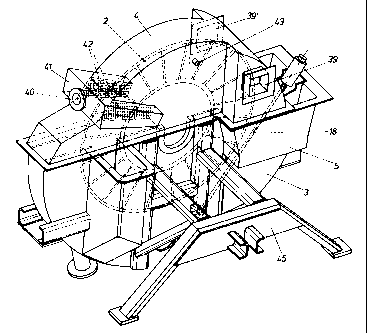
Fig. 4 illustrates a single-disk filter with filter disk 2 and filter
trough 3 to be employed for the processes according to the present
invention as a practical example. In the filter trough 3 mounted on stand
45 an agitator 18 is furthermore installed, which serves to homogenize the
suspension and sludge, respectively. A vapour dome 4 provided with openings
39,39' for pressure holding flaps is mounted above the filter trough 3.
These flaps open in dependance on the pressure difference between vapour
dome 4 and pressure space 17 (Figs. 1 to 3!) in which the filter is
positioned. They may be adjusted to a specific limiting value for opening
for instance by means of elastic force or counter weights. The vapour and
the heated compressed air, respE>ctively, is guided into a vapour chamber
41 via a muff 40, from where the vapour and the heated compressed air,
respectively, is guided directly onto the filter cake 19 already filtered
on via openings 42 provided on both sides of the filter disk 2, for
instance in the form of a perforated plate. The temperature and/or the
_ g _
~~.~2~~
pressure under the vapour dome 4 is measured via measuring probes 43 and
regulated according to the requirements. For special applications, for
instance for the filtration of readily sedimenting substances, further
installations, for instance guiding plates, special suspension feeding and
discharge means, may be provided for homogenizing sludge. The filter cake
is then thrown down into the fall shafts 5 and removed with scrapers,
respe~~tively, and falls into the funnel 6 for the material removed (not
shown here, but indicated in Figs. 1 to 3), the fall shaft 5 and funnel 6
possibly being tightly connected with each other.
The examples only serve to illustrate the invention, other applications,
for instance with rotary filters having several disks, drum filters or also
band filters in the pressures chamber, also being conceivable. The
application of the invention generally to the separation and filtration,
respectively, of liquid-solid-mixtures may be of considerable adavantage
under certain circumstances, ire particular in view of carrying out the
process economically.
_ g _