Language selection

Search

Patent 2102386 Summary

Third-party information liability

Some of the information on this Web page has been provided by external sources. The Government of Canada is not responsible for the accuracy, reliability or currency of the information supplied by external sources. Users wishing to rely upon this information should consult directly with the source of the information. Content provided by external sources is not subject to official languages, privacy and accessibility requirements.

Claims and Abstract availability

Any discrepancies in the text and image of the Claims and Abstract are due to differing posting times. Text of the Claims and Abstract are posted:

  • At the time the application is open to public inspection;
  • At the time of issue of the patent (grant).
(12) Patent: (11) CA 2102386
(54) English Title: PALLET CONTAINER COMPRISING A PALLET, AN OUTER HOUSING AND A PLASTICS INNER TANK
(54) French Title: CONTENANT CONSTITUE D'UNE PALETTE, D'UNE ENVELOPPE EXTERIEURE ET D'UN TUBE INTERNE EN MATIERE PLASTIQUE
Status: Expired and beyond the Period of Reversal
Bibliographic Data
(51) International Patent Classification (IPC):
  • B65D 19/18 (2006.01)
  • B65D 19/06 (2006.01)
  • B65D 77/06 (2006.01)
(72) Inventors :
  • DECROIX, CLAUDE (France)
  • SHUERT, LYLE H. (United States of America)
(73) Owners :
  • SOTRALENTZ S.A.
(71) Applicants :
  • SOTRALENTZ S.A. (France)
(74) Agent: BORDEN LADNER GERVAIS LLP
(74) Associate agent:
(45) Issued: 1999-04-06
(22) Filed Date: 1993-11-03
(41) Open to Public Inspection: 1994-05-05
Examination requested: 1995-08-08
Availability of licence: N/A
Dedicated to the Public: N/A
(25) Language of filing: English

Patent Cooperation Treaty (PCT): No

(30) Application Priority Data:
Application No. Country/Territory Date
P 42 37 157.0-22 (Germany) 1992-11-04

Abstracts

English Abstract


A pallet container comprising a pallet, an outer housing and a plastics inner tank. The
outer housing is releasably connected near its bottom edge to the pallet. The inner tank is
introduced into the outer housing supported on the pallet. The pallet is formed with a
peripheral groove for receiving the outer housing, which engages in the groove by way of its
bottom edge. The bottom edge of the outer housing is secured in the groove by retaining
tongues which extend through edge-closed recesses in the groove, engage over components
of the bottom edge of the outer housing and are releasably secured in the pallet.


French Abstract

Cette invention concerne une palette-caisse porte-réservoir composée d'une palette d'une caisse grillagée et d'un réservoir en plastique. La caisse est fixée à la palette de façon amovible par son extrémité inférieure. Le réservoir est placé dans la caisse montée sur la palette. Cette dernière comporte dans sa face supérieure une gorge périphérique destinée à recevoir la base des parois de caisse. La base de la caisse est maintenue dans la gorge susmentionnée au moyen de languettes de retenue insérées dans des logements ménagés dans la palette perpendiculairement à ladite gorge, lesdites languettes passant au-dessus de la barre inférieure formant la base de la caisse grillagée et étant verrouillées de façon amovible dans la palette.

Claims

Note: Claims are shown in the official language in which they were submitted.

-5-
CLAIMS:
1. A pallet container which comprises,
a pallet, an outer housing and a plastics inner container within the outer housing, said
housing being supported on said pallet;
a peripheral groove formed in the pallet,
a bottom edge to said housing received in said peripheral groove,
retaining tongues received in pockets in said pallet and securing said bottom edge of
said housing in said groove,
detent recesses formed in said tongues adjacent their ends and,
detent elements formed in said pallet engageable under load in the inner container into
said recesses for securing said tongues in reference position in said pockets.
2. A pallet container according to claim 1, the pallet being resiliently deformable in a
region of the detent elements, wherein in undeformed state of said region of the pallet the
detent elements leave clear the detent recesses in the tongues and when the inner container
is loaded the detent elements enter into the detent recesses by weight of filling material in the
inner container under resilient deformation of said resiliently deformable region of the pallet.
3. A pallet container according to claim 1 or 2, wherein the pallet is a square or
rectangular figure with rounded corners in plan view and the pockets are disposed along sides
of the figure.
4. A pallet container according to claim 1, 2 or 3, wherein the pallet is constructed from
two deep-drawn plastics shells, the bottom one of which is formed with pallet feet and the top
of which is formed with the peripheral groove, and the pockets are formed by complementary
facing relieved formations in the bottom shell and in the top shell respectively.
5. A pallet container according to claim 1, 2, 3 or 4, wherein the pallet is formed from
plastics.

-6-
6. A pallet container according to claim 1, 2, 3 or 4, wherein the pallet is formed from
a thermoplastic recycling plastic.

Description

Note: Descriptions are shown in the official language in which they were submitted.


CA 02102386 1998-04-01
- 1 -
The invention relates to a pallet container comprising a pallet, an outer housing and
a plastics inner tank, the outer housing being releasably connected near its bottom edge to the
pallet, the inner tank being introduced into the outer housing and supported on the pallet. The
term "pallet container" refers to a unit which has the construction described and which through
the agency of the pallet can be picked and manipulated by a fork lift truck or the like. The
pallet has a~propLiate entry channels for the arms of a fork lift truck. As a rule, the inner tank
is a thermoplastics blow moulding and serves to receive, store and transport substances, more
particularly chemical substances.
In conventional pallet constainers comprising a pallet, an outer housing and a plastics
inner tank, these components are manufactured independently of one another then
subsequently interconnected. In use, the outer housing is usually non-releasably connected to
the pallet.
In the known pallet container which forms the starting point for the invention
(US 5 100 000) the outer housing, which is in the form of a lattice of round steel rods, is
positively connected to the pallet by means of detent tongues which engage behind a bottom
peripherally extending round steel rod. These features simplify connection of the outer
housing to the pallet but demounting is elaborate because it is not a simple matter to bend
back the detent tongues.
Here disclosed is a pallet container of the construction described with a simpleconnection and disconnection arrangement between the outer housing and the pallet. This
enables the pallet to be released from the outer housing in operation, for example, in order
to reuse the pallet elsewhere. The outer housing can readily be drawn off the inner tank of
the disconnection if this is required and if the inner tank has been designed applupliately in
view of the weight of the filling material.
More particularly, in accordance with the invention, there is provided, a palletcontainer which comprises a pallet, an outer housing and a plastics inner container within the
outer housing, said housing ~eing supported on said pallet; a peripheral groove formed in the
pallet, a bottom edge to said housing received in said peripheral groove, retaining tongues
received in pockets in said pallet and securing said bottom edge of said housing in said
groove, detent recesses formed in said tongues adjacent their ends and, detent elements formed
in said pallet engageable under load in the inner container into said recesses for securing said
tongues in reference position in said pockets.

CA 02102386 1998-04-01
.,~ - 2 -
In a preferred embodiment of the invention, the receiving groove in the pallet is
contrived by resilient shaping. To ensure that the connection described is reliable in operation
and can be released reliably in a very simple way, the groove merges towards the centre of
the pallet into pockets with which the pallet is formed to receive the tongues.
In other embodiments of the invention the pallet, outer housing and inner tank can
have in plan any required contour, for example, a round contour. Preferably, however, the
pallet is in plan view a figure of square or rectangular contour with rounded edges and the
tongues and/or pockets are disposed along the sides of the square or rectangle. To secure the
tongues they are forrned near their ends with detent recesses in which detent elements of the
pallet engage and locate the tongues in their reference position in the pocket. This can be so
effected that the tongues are secure when the inner tank is full but that the securing can be
released quite simply when the tank is empty. To this end, the pallet is resiliently deformable
in the zone near the detent elements, the detent elements release the detent recesses in the
tongues in the undistorted state of such zone of the pallet and when the inner tank is full the
detent elements can be pressed into the detent recesses by the weight of the filling and with
resilient deformation of the resiliently deformable zones of the pallet.
The pallet can be made of a wide variety of materials. Preferably, the pallet ismoulded from plastics, more particularly a recycling thermoplastics. If the pallet is combined
from two deep-drawn plastics shells, the bottom of which has recessed pallet feet and the top
of which has the recessed peripheral groove, and the pockets are in the form of
complementary facing relieved formations in the top shell and in the bottom shell, the
formations co-operate with one another to form the pockets. The two plastics shells can be
joined together by thermoplastic welding or in some other way to form the pallet, the guide
channels for the fork arms of a fork lift truck being disposed between the pallet feet.
Embodiments of the invention will now be described with reference to the
accompanying drawings in which:
Fig. 1 is a partial and partly fragmented front elevation of a pallet container
embodying the invention,
Fig. 2 is an inverted plan view of the pallet of Fig. 1, and
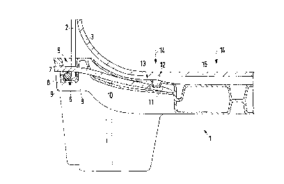
Fig. 3 is an enlarged view of the part A of Fig. 1.
The pallet container shown in the drawings comprises as its fundamental construction
a pallet 1, an outer housing 2 and a plastics inner tank or container 3. Near its bottom edge

CA 02102386 1998-04-01
3 -
the housing 2 is releasably connected to the pallet 1. The inner tank 3 is introduced into the
outer housing 2 and supported on the pallet 1. It is shown merely schematically in Fig. 1 that
the inner tank 3 can have an outlet 4. It also normally has a top closure having a lid and the
outer housing 2 extends up to the height of the top closure of the inner tank 3 in a manner
which is not shown.
As a comparison of Figs. 2 and 3 will show, the pallet 1 is formed with a peripheral
groove 5 to receive the outer housing 2, the same eng;~ging by way of its bottom edge 6 in
the groove 5.
The bottom edge 6 of the outer housing 2 is secured in the groove 5 by retainingtongues 7. The same extend through edge-closed recesses 8 in the walls of the groove 5. They
extend over parts of the bottom edge 6 of the housing 2 and are releasably secured in the
pallet 1. In the embodiment the tongues extend through an opening in the lattice construction
of the housing 2 and over the bottom peripheral lattice rod 9. As can be gathered from Fig. 3,
the groove S is contrived in the pallet by plastics shaping. Following on from the groove S
there can be seen, extending towards the centre of the pallet, pockets 10 adapted to receive
the tongues 7.
In the embodiment, and preferably, the pallet 1 is in plan of a rectangular contoured
figure with rounded corners. The tongues 7 and the pockets 10 are disposed along the sides
of the figure.
As can be seen in Fig. 3, the tongues 7 are formed near their end with detent recesses
11 in which detent elements 12 of the pallet 1 engage. Engagement of the elements 12 in the
recesses 11 locate the tongues 7 in their reference position in the associated pocket 10. In the
embodiment the recess 11 in the tongues 7 can be just a bore.
Fig. 3 shows a pallet container embodying the invention in a state in which the inner
tank 3 is empty. As will be al~pa~nl, the pallet 1 is resiliently deformable in the zone 13 of
the detent elements 12. The design is such that in the undeformed state of the associated zone
13 the detent elements 12 expose the recesses 11 adequately in the retaining tongues. Arrows
14 show how the weight of the filling material acts on the base 15 of the inner tank 3. The
base then sags further and settles on the top of the pallet 1; when the inner tank 3 is full the
detent elements 12 become pressed into the recesses 11 by the weight of the filling material
and with resilient deformation of the resiliently deformable zones 13 hereinbefore described.
The result is a reliable locking which copes with all transport stresses, vibrations or the like.
,. . .

CA 02102386 1998-04-01
- 4 -
Special significance attaches to a pallet container comprising a pallet 1, an outer
housing 2 and a plastics inner tank 3 which has been introduced into the outer housing 2 and
loaded on the pallet 1, which is formed with a peripheral groove 5 to receive the outer
housing 2, introduced by way of its bottom edge 6 into the groove 5, the edge 6 being secured
in the groove 5 by retaining tongues 7 formed near the tongue ends with detent recesses 11
in which detent elements 12 of the pallet 1 engage and determine the reference position of the
tongues 7 in pockets 10. The pallet 10 is resiliently deformable in the region of the detent
elements 12 and in the undistorted state of this region the detent elements 12 leave clear the
recesses 11 in the tongues 7. When the inner tank 3 is full the detent elements 12 are pressed
into the recesses 11 by the weight of the filling material and with resilient deformation of the
resiliently deformable zones 13 of the pallet 1.

Representative Drawing
A single figure which represents the drawing illustrating the invention.
Administrative Status

2024-08-01:As part of the Next Generation Patents (NGP) transition, the Canadian Patents Database (CPD) now contains a more detailed Event History, which replicates the Event Log of our new back-office solution.

Please note that "Inactive:" events refers to events no longer in use in our new back-office solution.

For a clearer understanding of the status of the application/patent presented on this page, the site Disclaimer , as well as the definitions for Patent , Event History , Maintenance Fee  and Payment History  should be consulted.

Event History

Description Date
Inactive: IPC from MCD 2006-03-11
Time Limit for Reversal Expired 2000-11-03
Letter Sent 1999-11-03
Grant by Issuance 1999-04-06
Inactive: Final fee received 1998-11-05
Pre-grant 1998-11-05
Notice of Allowance is Issued 1998-06-12
Letter Sent 1998-06-12
Inactive: Status info is complete as of Log entry date 1998-06-10
Inactive: Application prosecuted on TS as of Log entry date 1998-06-10
Inactive: IPC removed 1998-04-24
Inactive: First IPC assigned 1998-04-24
Inactive: IPC assigned 1998-04-24
Inactive: Approved for allowance (AFA) 1998-04-23
Request for Examination Requirements Determined Compliant 1995-08-08
All Requirements for Examination Determined Compliant 1995-08-08
Application Published (Open to Public Inspection) 1994-05-05

Abandonment History

There is no abandonment history.

Maintenance Fee

The last payment was received on 1998-10-23

Note : If the full payment has not been received on or before the date indicated, a further fee may be required which may be one of the following

  • the reinstatement fee;
  • the late payment fee; or
  • additional fee to reverse deemed expiry.

Please refer to the CIPO Patent Fees web page to see all current fee amounts.

Fee History

Fee Type Anniversary Year Due Date Paid Date
MF (application, 4th anniv.) - standard 04 1997-11-03 1997-09-23
MF (application, 5th anniv.) - standard 05 1998-11-03 1998-10-23
Final fee - standard 1998-11-05
Owners on Record

Note: Records showing the ownership history in alphabetical order.

Current Owners on Record
SOTRALENTZ S.A.
Past Owners on Record
CLAUDE DECROIX
LYLE H. SHUERT
Past Owners that do not appear in the "Owners on Record" listing will appear in other documentation within the application.
Documents

To view selected files, please enter reCAPTCHA code :


To view images, click a link in the Document Description column. To download the documents, select one or more checkboxes in the first column and then click the "Download Selected in PDF format (Zip Archive)" or the "Download Selected as Single PDF" button.

List of published and non-published patent-specific documents on the CPD .

If you have any difficulty accessing content, you can call the Client Service Centre at 1-866-997-1936 or send them an e-mail at CIPO Client Service Centre.


Document
Description 
Date
(yyyy-mm-dd) 
Number of pages   Size of Image (KB) 
Description 1998-04-01 4 203
Abstract 1998-04-01 1 16
Claims 1998-04-01 2 45
Cover Page 1999-03-31 1 50
Cover Page 1995-04-08 1 28
Abstract 1995-04-08 1 20
Claims 1995-04-08 2 68
Drawings 1995-04-08 2 50
Description 1995-04-08 7 267
Representative drawing 1999-03-31 1 9
Commissioner's Notice - Application Found Allowable 1998-06-12 1 164
Maintenance Fee Notice 1999-12-01 1 178
Correspondence 1998-11-05 1 35
Fees 1995-10-17 1 37
Fees 1996-10-15 1 39
PCT Correspondence 1993-11-18 1 20
Courtesy - Office Letter 1995-09-15 1 37
Prosecution correspondence 1994-04-14 2 40
Prosecution correspondence 1995-04-08 1 21
Prosecution correspondence 1997-12-17 14 433
Prosecution correspondence 1995-11-06 1 27
Examiner Requisition 1997-06-17 2 61