Note: Descriptions are shown in the official language in which they were submitted.
1
ITVi Case 67? 0
CARRIER STOCK 6dITH TEAR-OPEN TAES
mechni ca'~ ~'~ e~ d of ~-he Invention
This invention pertains to carrier stock for
machine application to substantially identical
containers. The carrier stock is severable,to form
individual carriers with separate apertures to receive
the individual containers. Certain aperture-defining
band segments including certain band segments extending
in generally diagonal directions when the carrier stock
is unstressed have tear-open tabs to enable the
individual containers to be easily removed.
BacJcaround of the Inven on
Typically, carrier stock with individual container-
receiving apertures for machine application to
substantially identical containers is formed, as by die-
cutting, from a single sheet of resilient polymeric
material, such as low density polyethylene. A recent
example of carrier stock with tear-open tabs ig
2p disclosed in Marco U.S. Patent Na. 5,020,661, which
discloses two longitudixaal rows of container-receiving
apertures.
As diSClo~ed iri the Marco patent noted above, the
container-receiving apertures are arranged in two .
25' longitudinal rows and are defined by band segments,
~hieh include outer band segments extending in generally
longitudinal directions when the.carrier stock is
unstressed. Each outer band segment has a tear-open tab
and is slitted to,f~cilitate tearing of such outer band
30 segment when the tear-open tab is pulled.
An earlier example of carrier stock with tear-open
tabs is disclosed in Olsen U.S. Patent No. 4,064,99,
which also discloses two longitudinal rows of cantainer°
receiving apertures. As disclosed therein, outer band
35 segments have tear-open tabs, each having a slit at an
acute angle to a line drawn at its base.
A different approach to providing carrier stock
with tear-open capability, via elements attaching band
segments to pull-tab rings on the containers, is
5~ disclosed in cordon U.S. Patent No. 5,015,750, which
also discloses two longitudinal rows of container-
receiving apertures.
Carrier stock with container-receiving apertures
arranged in three longitud3.3~a1 rows is known. as
exemplified in Klygis U.S. Patent No. ~,o1e,331. This
patent does riot teach tear--open capability.
,~t~n~max~' of the Tnventi~n
This invention provides an improvement in carrier
stack formed from a single sheet of resilient polymeric
material, such as low density polyethylene, for machine
application 'to substantially identical containers. The ,
improvement is useful where the corutainer-receiving
apertures are arranged in two or more longitudinal rows,
and where the band segments defining the container-
2o receiving apertures include generally diagonal band
segynents, each of which extends in a generally diagonal
direction when the carrier stock is unstressed.
broadly, this invention oonteanplat~s that some of the
generally diagonal band segments-have tear-open tabs.
Specifically, dais invention also contemplates
that, where the longitudinal rows include two outer rows
I and an inner row; the generally diagonal band segments
having tear-open tabs may include one of the band .
segments defining each respective one of the container-
3o receiving apertures of the inner row.
Tn a first contemplated ezabodi~aent, which
aontempla~tes that the band segments include outer band
segments extending in generally longitudinal directions
when said stock ie unstressed, each outer band segment
has a tear-open tab.
- 3 ..
Preferably, in the first contemplated embodiment,
the container-receiving apertures of each carrier define
a rectangular axray having two shorter sides and two
longer sides, each shorter side being comprised of two
5. such apertures, and each longer side being comprised of
a larger number of such apertures. Two of the tear-open
tabs may be thus accessible from each of the shorter
sides, and wherein each of the remaining tear-open tabs
is accessible from one of the longer sides.
l0 In a second contemplated embodiment, the generally
diagonal band segments having tear-open tabs include one
of the band segments defining each respective one of the
outer row container-receiving apertures, as well as one
of the band segments defining each respective one of the
15 container-receiving apertures of the inner row.,
Preferably, in the second contemplated embodiment,
the container-receiving apertures of each carrier define
a rectangular array having two shorter sides and two
longer sides, each shorter side being comprised of two
20 such apertures, and each longer side being comprised of
a larger number of such apertures. Each of the tear-
open tabs may be thus accessible from one of the 1~nger
sides.
In either embodiment, if each tear-open tab on a
25 diagonal.bancl segment has generally parallel edges, such
tear-open tab may have a slit spaced by a tearable
'bridge friam one such edge, namely the edge that when the
carrier stock is unstressed is closer t~ another
d.iag~ual band segment with~ut a tear-open tab, to reduce
30 problems associated with winding ~or unwinding of strips
~f carrier a " .. . .
'these and other objects, features, and ad~rantages
of this invention are evident from the following
description of a preferred embodiment of this invention
35 with reference to the accompanying drawings.
~~,~_~~~~; )~
Bri ef De~~~~p~~r~of the lDraw~nas
Figure 1 is a fragmentary, plan view of a carrier
severed from carrier stock according to a first
contemplated embodiment of this invention.
5. Figure 2 is arisenlarged, fragmentary detail of a
band segment having a tear-open tab.
Figure 3 is a fragmsnta~y, plan view of a carrier
severed frown carrier stock according to a second
contemplated embodiment of this invention.
~a,~iled Descp,~p~i on of ~~errec~l Embodiment
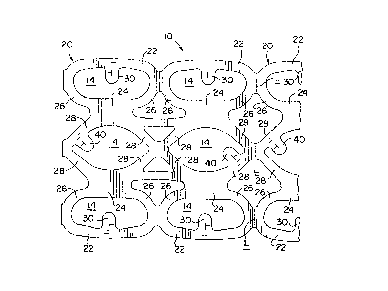
in Figure 1, carrier stock to according to a fir6t
contemplated embodiment of this invention is suitable
for machine application to substantially identical
containers (not shown) such as beverage cans of a type
used commonly for beer, soft drinks, and other
beverages. The carrier stock 10 is formed with separate
apertures 14 in three longitudinal y-ows to receive the
individual cowtainers.
This invention is useful with cans, bottles, and
- ~2.0 ' other containers of various types. If the containers
are sans of a type having a chime at one end or at each
end, the carr~.er stock 10 can be machine applied to side
galls of the containers so as to grip-such walls at suoh
chimes, br so as to grip such walls away from such
chimes.
The oarrier stock 10 is formed in an indeterminate
'length, a's by die-cutting, from a single sheet of
resilient ~ol~meric material. ~ preferred material is
low density polyethylene. ~ preferred thickness for
such stock 1~, if low density polyethylene is used, is
about 15 mils.
The carriex stock 10 is severable along transverse
lines g~, so as to form individual carriers 20 that are
substantially iderit~.cal. In Figure 1, one carrier a0 is
slaowr~ completely, and another is shown fragmentarily.
CA 02102453 1998-07-30
- 5 -
As shown in Figure 1, the lines j~ may be perforated to
facilitate severing the carrier stock 10.
The carrier stock 10 is formed, for each individual
carrier 20, with integrally joined band segments
5. defining six separate apertures 14 in a rectangular
array with three longitudinal rows (two outer rows and
an inner row) and two transverse ranks.
The band segments include outer segments 22
extending in a generally 1~ngitudinal direction when
such stock 10 is unstressed, inner segments 24 extending
similarly, curved band segments 26 included among the
band segments defining the container-receiving apertures
14 in the outer rows, and generally diagonal segments 28
included among the band segments defining the container-
receiving apertures 14 in the inner row. As shown, when
the carrier stock 10 is unstressed, each generally
diagonal segment 28 extends in a generally diagonal
direction.
Each outer segment 22 is formed with a tear-open
tab 3o extending in a generally transverse direction,
into the container-receiving aperture 14 bounded partly
by such outer segment 22 when the carrier stock 10 is
unstressed. one generally diagonal segment 28 partly
bounding each container-receiving aperture 14 in the
middle row is formed with a tear-open tab 40 extending
in a generally diagonal direction, into such container-
receiving aperture 14, when the carrier stock 10 is
unstressed.
The tear-open tabs 30, 40, are similar. Each may
be similar to the tear-open tabs disclosed in Marco U.S.
Patent No. 5,020,661, the disclosure of which may
be referred to for further details. preferably, as shown
in Figure 2, in which an exemplary band segment 28
having an exemplary tear-open tab 40 is shown
fragmentarily, each tear-open tab 40 and the diagonal
i.
. -6-
band segment 28 fe~rmed with such tear-open tab 40 are '
slitted in a si~ailar manner so as to have multiple
slits, which facilitate tearing of such band segment 28
when such tear-open tab 40 is pulled.
5' Preferably, as shown in Figure 2, these slits are
comprised of two slits farraed in the tear-open tab 40
and two slits formed in the diagonal band segment having
the tear-open tab 40. A first slit 42 is formed in the
tear-open tab 40 so as to b~e generally perpendicular
with a lateral edge 44 of such tab 40. The first slit
42 is spaced from the tab edge 44 by a testable bridge
defined by the first slit 42 and by the tab edge 4~. A
second slit 46 is formed in such tab 40 so as to be
generally perpendicular to the first slit 42. The
15; second slit 46 intersects the first slit 42. A third
slit 48 and a fourth slit 50 are formed in the band
segment 28 having the tear-open tab 40, as in Marco U.S.
patent No. 5,020,661. The slits 48, 50, are formed in
such segment 28 so as to be generally parallel with ~sach
other, so as to be generally perpendicular to the second
flit 46, and so as to define testable bridges between
the second slit 46 and the third slit~48, between the
third slit 48 and the Fourth slit~5o, and between the
fourth slit and ane of the aadditional apertures 16,
namely an aperture that is bounded partly by the band
'segment f8 having the tear-span tab 40.
When the carrier stag 10 is unstressed, the tab
edge 44 spaced from the first slit 42 by a testable
bxidge, as hated above, is close to a portion of an edge
52 of the aperture 14 (into which the tear-span tab 40
extends) where the apexture edge 52 is defined by a
diagonal band segment 28 without a tear-open tab 40.
The tab edge 44 and the aperture edge 52 meet at a
Curved transitian 58 to avoid a concentration of
stresses. Tn contrast, an opposite edge 60 of the tear-
:; . ~. .,
-?-
open tab 40 defines a relatively large, acute angle With
a portion of another edge 62 of the same aperture 14
where the aperture edge 62 is defined by the band
segment 23 having such tab 40. The tab edge 60 and the
aperture edge 62 meet at a curved transition 64 to avoid
_ ~ a concentration of stresses. The tab edges 44, 60, are
generally parallel with each other and are connected by
a curved edge 66 of the tear-open tab 40.
In the tear-open tabs 4.~,, it is preferable to
lp locate the slits 42, ~6, riser the tab edges 44, rather
than near the tab edges 60. If the carrier stock 10 is
wound on a core (net shown) for storage or shipment,
some of the tear-open tabs 40 array tend to interlock with
one another. If the slits 42, 46, were near the tab
edges 60, rather than the tab edges 44, and if some of .
the tearable bridges were to be inadvertently torn, the
slits 42 of some tabs 40 could interlock, which would
interfere with efficient and effect~.ve wi»ding or
unwinding of the carrier stock lo. ~ ,
In each carrier 20, the contaiaaer-receiving
apertures 14 define a rectangular array, which has two ,
shorter sides each comprised of two such apertures 14
and two longer sides each comprised of three such
apertures 14. Two of the tear-open tabs 30 are
~5 accessible to a urea: from eadh of the shorter sides.
,. Each of the tsar-open tabs 40 is accessible to a user
froaa a respective one of the longer sides.
Tn Figure 3o carrier stock lo' according to a
second contemplated embodiment of this i»ventio» is
suitable is substitutable for the carrier stock to for
machine application to substantially.identical
containers (not shown) similar to the containers
discussed above. Except as illustrated in the drawings
and described herein, the carrier stock 10' is sianilar
to the carrier stock 10. Thus, the carrier stock 10° is
': : . . , ..... ~ '. . : ~. : : ; :i ' ~ ; . ; . . .
r; : . : - ;, ' .,; ; , ' .:,,, ;;',;r . ,, .; ,;
S
,...-., ~ . '' :~ ', 3
8
severable along, transverse lines ~,' (similar to the
lines ~ discussed above) to form individual carriers 20'
w that are substantially identical.
The carrier stock 10' is formed, for each
individual carrier 20~, with integrally joined band
segments defining six separate apertures 14' in a
rectangular array with three longitudinal rows (two
outer rows and an inner row) and two transverse ranks.
The band segments include outer segments 22' extending
in a generally longitudinal direction.when such stock l0
is unstressed, inner segments 24' extending similarly,
generally diagonal band segments 26° included among the
band segments defining the container-receiving apertures ..:
14 in the outer rows, and generally diagonal segments
28° included among the band segments defining the
container-receiviYag apertures 14 i;n the inner row. ,~s
shown, when the carrier stock 10 is unstressed, each
generally diagonal segment 26°, 28', extends in a
generally diagonal direction.
ene generally diagonal segment 22' at each
container-receiving aperture 14° in each outer row ie
formed with a tear-open tab 30' extending in a generally '.
transverse direction, into such container-receiving -
apex°ture 14°, When the carrier stock l0' is unstressed.
25. One generally diagonal seganent 26' at each container-
receiving aperture ~.4' irn the middle row $.s formed with
a tear-open tab 40' Qxtending in a generally diagonal
' direction, into such contairesr-receiving aperture 14°,
when the carrier stock lo' is unstressed.
The tear-open tabs 30°, 40', are similar, each
being similar to the tear-open tads 30, 40, described
.. , above and, to the tear-open tabs disclosed in l~arc~ U.S.
.. . ; ' patent No. 5,020,661. Further, each tear-open tab 30,
40, and the band segment 22, 28, formed with such tear-
open tab 30, 40, are slatted in a similar mariner so ae
-..
. ~ .1
9
to have multiple slits, which are similar to the slits
described above and which facilitate tearing of such
band segment 22, 28, when the tsar-open tab is pulled.
In each carrier 200, the container-receiving
5, apertures 14 define a rectangular array, which has two
shorter sides each comprised of two such apertures 14'
and twa longer sides each comprised of three such
apertures 14'. Two of the tear-open tabs 30' and one of
the tear-open tabs 40' are,accessible to a user from
each longer side.
~larious modifications may be made in either
embodiment described above without departing from the
scope and spirit of this invention.