Note: Descriptions are shown in the official language in which they were submitted.
-~ 210?.. 543
~ ..
ETH 003 PA - 1 -
LIGATING CLIP -
~ackground of the Invention
The present invention relates generally to surgical
fasteners and, more particularly, to a surgical ligating clip
5 having laterally positioned engagement means for receiving a - ~ -
closing force from clip-applying jaws.
Surgical ligating clips have been used in the prior art
to ligate blood vessels, ducts and other body tissue during
surgery. Such clips have been produced from metals, such as
titanium, tantalum and stainless steel. Clips made from
polymeric materials are also known and may be preferable to metal
clips in some surgical procedures. This is because polymeric
clips do not disrupt post-operative diagnostic procedures, such
as X-ray imaging, CAT scanning and the like. Further, when
absorbable polymeric clips are employed, there is little
likelihood of a long term foreign body reaction by the host in
which the clips are implanted.
one example of a prior art polymeric clip is disclosed
in U.S. Patent No. 4,527,562, and comprises two leg members
joined at their proximal ends by a hinge, with locking means
provided at the distal ends of the leg members for securing ~ame
in a closed position. The clip further includes bosses provided
on upper and lower outer surfaces of the top and bottom leg
members, respectively, for mating with jaws of a clip-applying
instrument. The clip is secured to body tissue by applying
sufficient force via the clip-applying instrument to the upper
and lower outer surfaces of the leg members to move them toward
one another until the locking means locks the leg members in a
closed position. This prior art ligating clip is commonly used
in open surgical procedures.
For endoscopic applications, a ligating clip must be of
a size which permits it to pass through a cannula passageway
before being secured to body tissue. An additional limitation on
its size is presented when the outer ~urfaces of its leg members
are gripped by ~aws of a clip-applying instrument. This results
:: , . . .
- ?.102fi~3
ETH 003 PA - 2 -
because the combined height of the clip and the jaws should not
exceed the diameter of the cannula passageway. Exemplary of such -~
a clip and applier is that disclosed in commonly assigned U.S.
patent application Serial No. 07/680,215, now U.S. Patent No.
_ , the disclosure of which is hereby incorporated
by reference.
With polymeric clips, these size limitations may be
problematic since the clip8 must be sufficiently stiff to ensure
proper ligation of the attached tissue. Because the polymeric
ligating clip in noted U.S. Patent No. 4,527,562 is gripped on
its upper and lower outer surfaces before being secured to body
tissue, the clip dimensions are limited for endoscopic
applications.
. -. .....
Accordingly, there is a need for a ligating clip and
clip-applying instrument in which the clip-applying instrument
grips the clip at locations other than on the upper and lower --
outer surfaces of the leg members of the clip.
:. .:. : .
Summary of the Present Invention
This need is met by the present invention wherein an -~
improved ligating clip is provided which includes engagement
means positioned laterally on its leg members for engagement with
a clip-applying instrument. Due to the lateral location of the
engagement means, the clip size can be maximized with respect to
the diameter of a cannula 80 that the upper and lower outer
surfaces of the top and bottom leg members, respectively, extend
substantially completely across the diameter of the cannula
passageway as the clip passes in a semi-closed state
therethrough. Mbximizing clip size allows the beam stiffness of
the leg members to be increased. This, in turn, minimizes
flexure or springback of the leg members when the clip is secured
to body tissue.
In accordance with a first aspect of the present
invention, a surgical fastener is provided which is adapted to be
secured in a closed position about body tissue by a fastener-
. ~
:,''.'~ :'. ':..
. .,'.. ,:,-
, . . : :::..
r;~
~ 21Q2543 ~
ETH 003 PA - 3 -
applying instrument. The surgical fastener comprises first and
second leg members, each having distal and proximal ends.
Resilient hinge means is provided for connecting the first and
second leg members at their proximal ends. Latch means is
associated with the distal ends of the first and second leg
members for locking the first and second leg members in a closed
position about the body tissue. Engagement means is positioned
laterally on at least one of the first and second leg members for
engaging with the fastener-applying instrument to allow the
instrument to move the first and second leg members toward one
another until the latch means locks the first~and second leg
members in a closed position about the body tissue.
Preferably, the engagement means comprises first and
second lateral extensions integrally formed with the first leg
member, and third and fourth lateral extensions integrally formed
with the second leg member. In accordance with a first
embodiment of the present invention, the first and second lateral
extensions extend from opposing lateral faces of the first leg
member and the third and fourth lateral extensions extend from
opposing lateral faces of the second leg member. The first leg
member and its associated lateral extensions and the second leg
member and its associated lateral extensions each define a
substantially T-shaped cross section.
In accordance with a second embodiment of the present
invention, the first leg member and its associated lateral
extensions and the second leg member and its associated lateral
extensions each define a substantially trapezoidal cross section.
According to a third embodiment, the first leg member and its
associated lateral extensions and the second leg member and its
associated lateral extensions each define a substantially bell-
shaped cross section.
In accordance with a second aspect of the present
invention, a combination is provided comprising a clip-applying ~-
instrument and a ligating clip which is adapted to be secured in
a closed po~ition about body tissue-by the clip-applying
:
~ l Q " ~ ~ 3
ETH 003 PA - 4 -
instrument. Preferably, the clip i9 configured in the same
manner as the clip discussed above with respect to the first
aspect of the present invention.
In accordance with a third aspect of the present
S invention, a method is provided for securing a ligating clip in a
closed position about body tissue. The ligating clip comprises
first and second leg members having distal and proximal ends,
hinge means for connecting the first and second leg members at
their proximal ends, latch means associated with the distal ends
of the first and second leg members for locking the first and
second leg members in a closed position, and engagement means,
positioned laterally on at least one of the first and second leg
members, for engaging with a fastener-applying instrument. The ~`
method comprises the steps of: engaging the laterally positioned
engagement means with the fastener-applying instrument:
positioning the clip such that the leg members extend on opposite - -~sides of the body tissue; and employing the fastener-applying ~ -
instrument to move the first and second leg members toward one -~
another until the latch means locks the first and second leg -
members in a closed position with the body tissue engaged
therebetween. -
Preferably, the method further comprises the step of -
passing the clip through the passageway of a cannula prior to
performing the step of positioning the clip such that the leg
25 members extend on opposite sides of the body tissue. ~ --- ~ `
The fastener-applying instrument may move the first and -
second leg members toward one another by applying a closing force
to either the engagement means or upper and lower outer surfaces
of the first and second leg members.
Accordingly, it is an object of the present invention
to provide an improved surgical fastener which includes ~ .
engagement means positioned laterally on at least one of its leg
members for engaging with a fastener-applying instrument. It is
another object of the present invention to provide an improved
8terile ligatlng clip which includes~lateral extensions provided
,
,
^` 210~`~43
ETH 003 PA - 5 -
on its leg members for engaging with a clip-applying instrument.
It is a further object of the present invention to provide an
improved ligating clip having engagement means positioned
laterally thereon 90 as to allow maximum use of a cannula
passageway during endoscopic applications. It is yet another
object of the present invention to provide a clip-applying
instrument for engaging with lateral extensions on a ligating
clip and applying a closing force to either the lateral
extensions or the upper and lower outer surfaces of the clip.
These and other objects and advantages of the present invention
will be apparent from the following description, the accompanying
drawings and the appended claims.
Brief Descrip~ion of the Drawings
Fig. 1 is a perspective view of a ligating clip and
jaws of a clip-applying instrument, each constructed in
accordance with a first embodiment of the present invention, with
the upper jaws shown partially broken away;
Fig. 2 is a perspective view of the clip of Fig. 1
shown secured to a vessel;
Fig. 3 is a perspective view of a clip-applying
instrument and a cannula with the cylindrical tubular extension
of the instrument inserted through the passageway of the cannula
for use during an endoscopic procedure;
Fig. 4 is a distal end view of the cannula of Fig. 3
with the jaws of the clip-applying instrument gripping the clip
of Fig. 1 within the cannula passageway;
Fig. 5 is a view taken along section line 5-5 in Fig.
4;
Fig. 6 is a perspective view of a ligating clip formed
in accordance with a second embodiment of the present invention;
Fig. 7 is a distal end view of a cannula having jaws
gripping the clip of Fig. 6 within the cannula passageway;
Fig. 8 is a per~pective view of a ligating clip formed
ln accordance with a thlrd emoodiment of the pre~ent invertion:
:: ~ - , .
- 2~ 02~3
ETH 003 PA - 6 -
Fig. 9 i8 a distal end view of a cannula having jaws
gripping the clip of Fig. 8 within the cannula passageway;
Fig. 10 is a side view, partially in section, showing :~
an alternative embodiment of a clip-applying instrument including
gripping arms and a camming element supporting the clip of Fig. 1
before acting to close the clip about a vessel; and
Fig. 11 is a side view, partially in section,
illustrating the movement of the camming element relative to the
gripping arms of the clip-applying instrument of Fig. 10 for
10 closing the clip about the vessel. ~ ;
...
Detailed Description Qf the Preferred Embodiments
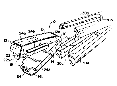
Reference is now made to Fig. 1, which illustrates a
ligating clip 10 formed in accordance with a first embodiment of - ,~
the present invention. The ligating clip 10 includes first and
second leg members 12 and 14 connected at their proximal ends 12a
and 14a by a resilient hinge section 16. Provided at the distal ~ ~-
ends 12b and 14b of the first and second leg members 12 and 14 is ---
latch means 18 for locking the leg members 12 and 14 in a closed -
position about body tissue, such as a vessel 20, shown in Fig. 2.
In the illustrated embodiment, the latch means 18 comprises a ~ -
hook member 22 which is adapted to be lockingly received within a ~-
recess 24 located in the distal end 14b of the second leg member
14. The hook member 22 i8 provided with a sharp edge 22a for
penetrating any connecting tissue (not shown) which might
surround the vessel 20. ;
First and second lateral extensions 24a and 24b are
integrally formed with the first leg member 12, and third and
fourth lateral extensions 24c and 24d are integrally formed with
the second leg member 14. The lateral extensions 24a-24d extend
outwardly from opposing side walls of the leg members 12 and 14
and are adapted to receive a clip closing force. The force -
applied to lateral extensions 24a-24d cause the distal ends 12b
and 14b of the leg members 12 and 14 to move toward one another
21 0~3
ETH 003 PA - 7 -
until the latch mean~ 18 locks them in a closed position, with
the vessel 20 engaged therebetween as shown in Fig. 2.
It will be understood by those skilled in the art that
a variety of clip-applying instrument~ can be used for securing
the ligating clip 10 to body tissue. One example of such a clip-
applying instrument 32 is shown in Fig. 3. The instrument 32
includes jaws 30a-30d, which are more clearly shown in Figs. 1, 4
and 5, a housing 33, a pivotable trigger 34, and a cylindrical
tubular extension 36. A suitable actuating mechanism (not shown)
extends through the housing 32 and the tubular extension 36 and
connects with the jaws 30a-30d at it~ distal end and with the
trigger 34 at its proximal end. Opening and closing of the jaws
30a-30d is effected by a surgeon through actuation of the trigger
34.
For use during an endoscopic procedure, the clip 10 is
held between the jaws 30a-30d, adjacent to the distal end 36a of
the tubular extension 36, and is inserted through a passageway 40
of a cannula 42, as shown in Fig. 3. The cannula has previously
been inserted through tissue 50 in a known manner. The clip 10
passes through the cannula passageway 40 in a partially closed
state, as shown in Figs. 4 and 5. After the jaws 30a-30d and the ~ -
clip 10 have passed beyond the distal end 42a of the cannula 42,
the jaws 30a-30d separate to allow the clip 10 to expand to its
substantially fully opened state. By manipulating the clip-
applying instrument 32, a surgeon positions the clip 10 eo that
its leg members 12 and 14 extend on opposite sides of the vessel
20 or other body tissue to be ligated. The trigger 34 is then
actuated by the surgeon, causing the jaws 30a-30d to apply a
force to the lateral extensions 24a-24d. This moves the leg
members 12 and 14 toward one another until the latch means 1~
locks the leg members 12 and 14 in a closed position, with the ~ ;
vessel 20 engaged therebetween. ~-
A ligating clip 60, configured in accordance with a
second embodiment of the present invention, is shown in Figs. 6
and 7, where like reference numerals indicate like elements. In
',.
~ 1 ~ 2 5 4 3
ETH 003 PA - 8 -
this embodiment, the clip 60 includes a first leg member 62 which
i9 integrally formed with first and second lateral extensions 64a
and 64b. Together, the lateral extensions 64a and 64b and the
first leg member 62 define a substantially trapezoidal cross
section. The clip 60 further includes a second leg member 63
which is integrally formed with third and fourth lateral
extensions 64c and 64d. The lateral extensions 64c and 64d and
the second leg member 63 also define a substantially trapezoidal
cross section.
In accordance with the second embodiment of the present
invention, the clip-applying instrument is provided with jaws
66a-66d having substantially planar inner surfaces 68a-68d for
engaging the lateral extensions 64a-64d of the ligating clip 60,
see Fig. 7. The outer surfaces 69a-69d of the jaws 66a-66d are
15 curved to allow easy passage through, and full use of, the -~
circular cannula passageway 40. .-
A ligating clip 70, formed in accordance with a third
embodiment of the present invention, is shown in Figs. 8 and 9,
where like elements are referenced by like numerals. In this
embodiment, the clip 70 includes a first leg member 72 and
integrally formed first and second lateral extensions 74a and
74b. Together, the first leg member 72 and the lateral
extensions 74a and 74b define a substantially bell-shaped cross ~ ;
section. The clip 70 further includes a second leg member 73 and
integrally formed third and fourth lateral extensions 74c and
74d. Together, the second leg member 73 and the lateral
extensions 74c and 74d also define a bell-shaped cross section.
In accordance with the third embodiment of the present
invention, the clip-applying instrument is provided with jaws
76a-76d having curved inner surfaces 78a-78d conforming to the
curved lateral extensions 74a-74d for secure engagement with
same, see Fig. 9. The outer surfaces 79a-79d of the ~aws 76a-76d
are curved to allow easy passage through and full use of the
clrcular cannula pa-~ageway 40.
. ~ .. ..
:
- 2102fi~3
ETH 003 PA - 9 -
An alternative embodiment of the clip-applying
instrument of the present invention i8 shown in Figs. 10 and 11.
In this embodiment, the clip-applying apparatus comprise~ four
gripping arms 80, only two of which are shown, and a
reciprocating camming element 82. The gripping arms 80 engage
with the lateral extensions 24a-24d of the ligating clip 10 of
Figs. 1 and 2 and act with the camming element 82 to hold the
clip 10 in a partially closed state as the clip 10 passes through
the cannula passageway 40. After passing beyond the distal end
42a of the cannula 42, the camming element 82 is moved in a
direction, denoted by arrow 84 in Fig. 10, away from the clip 10
to allow the clip 10 to expand to its substantially fully opened
position. With the clip 10 thus expanded, it is positioned 90
that its leg members 12 and 14 are on opposite sides of the
vessel 20 or other tissue to be ligated. The camming element 82
is then moved in a direction, denoted by arrow 86 in Fig. 11,
toward the clip 10 to apply a force against upper and lower outer
surfaces 12c and 14c of the leg members 12 and 14. Leg members
12 and 14 are moved toward one another until the locking means 18 m
locks the leg members 12 and 14 in a closed position 80 as to -`
close off the lumen of the vessel 20.
Following securement of the clip 10 to the vessel 20,
the camming element 82 is moved away from the clip 10. The
camming element 82 and the gripping arms 80 are then withdrawn
25 from the cannula 42. -~
The ligating clips of the present invention may be ````-
molded from a biologically acceptable polymeric material which
may be absorbable or non-absorbable. Preferred absorbable
polymers include poly(p-dioxanone), polyglycolide, polylactide,
polycaprolactone, polyhydroxybutyrate, polyhydroxyvalerate,
polyanhydrides, and copolymers thereof. Preferred non-absorbable
polymers include nylon, polyester and polypropylene. The clips
may also be cast or machined from solid polymeric materials. The
clips may also be for;med of other suitable materials such as a
metal.
.,
.. . . . ..
~102~43
ETH 003 PA - 10 -
As will be appreciated by those skilled in the art, the
ligating clips of the present invention may be used in open
surgical procedures. The aforementioned clip-applying
instruments or like apparatus may be employed for securing the
clips to body tissue during such procedures.
It is further contemplated by the present invention
that the first leg member and its associated lateral extensions
and the second leg member and its associated lateral extensions
may form other shapes in cross section in addition to those which
are illustrated with regard to the previously noted embodiments
of the present invention. -Additionally, the lat~r~ extensions
on the first and second leg members may be positioned 90 that
they do not increase the area of the clip that engages body
tissue.
It is also contemplated that a clip-applying
instrument, preloaded with a plurality of ligating clips of the
present invention, may be employed for feeding the ligating clip8
successively to a securement position and for subsequently
securing each clip to body tissue as each clip is moved to that -~
position.
Having described the invention in detail and by -
reference to preferred embodiments thereof, it will be apparent
that modifications and variations are possible without departing
from the scope of the invention defined in the appended claims.
What is claimed is:
' ' :" ~ ''''
. . .
: