Language selection

Search

Patent 2102737 Summary

Third-party information liability

Some of the information on this Web page has been provided by external sources. The Government of Canada is not responsible for the accuracy, reliability or currency of the information supplied by external sources. Users wishing to rely upon this information should consult directly with the source of the information. Content provided by external sources is not subject to official languages, privacy and accessibility requirements.

Claims and Abstract availability

Any discrepancies in the text and image of the Claims and Abstract are due to differing posting times. Text of the Claims and Abstract are posted:

  • At the time the application is open to public inspection;
  • At the time of issue of the patent (grant).
(12) Patent: (11) CA 2102737
(54) English Title: MODULAR SHELVING INTERCONNECTION ASSEMBLY
(54) French Title: ASSEMBLAGE POUR RAYONNAGE MODULAIRE
Status: Expired and beyond the Period of Reversal
Bibliographic Data
(51) International Patent Classification (IPC):
  • A47B 95/00 (2006.01)
  • A47B 57/36 (2006.01)
  • F16B 12/24 (2006.01)
(72) Inventors :
  • GOLLICK, THOMAS W. (United States of America)
(73) Owners :
  • THOMAS W. GOLLICK
(71) Applicants :
  • THOMAS W. GOLLICK (United States of America)
(74) Agent: LAMBERT INTELLECTUAL PROPERTY LAW
(74) Associate agent:
(45) Issued: 1999-08-24
(22) Filed Date: 1993-11-09
(41) Open to Public Inspection: 1994-06-10
Examination requested: 1995-08-18
Availability of licence: N/A
Dedicated to the Public: N/A
(25) Language of filing: English

Patent Cooperation Treaty (PCT): No

(30) Application Priority Data:
Application No. Country/Territory Date
07/988,248 (United States of America) 1992-12-09

Abstracts

English Abstract


ABSTRACT OF THE DISCLOSURE
A modular shelving interconnection assembly is dis-
closed. The assembly has two (2) substantially upright,
spaced-apart side panels with holes extending through
their lateral surfaces at approximately equal distances
from their bottoms. Tabs of shelf support units extend
through the holes in the side panels. Pegs in the shape
of split, truncated cones extend through the holes in the
tab on the outside of the panels, and cooperate with the
holes in the tabs and the outside surface of the panels to
secure the shelf-support units to the panels. The modular
assembly may be repeated in the direction of the shelf
support unit to extend it to a wall-length shelving unit.


Claims

Note: Claims are shown in the official language in which they were submitted.

THE EMBODIMENTS OF THE INVENTION IN WHICH AN EXCLUSIVE
PROPERTY OR PRIVILEGE IS CLAIMED ARE DEFINED AS FOLLOWS:
1. A modular shelving interconnection assembly
comprising:
two (2) substantially upright, spaced-apart side
panels, said panels having a plurality of pairs
of holes extending through their lateral surfaces
at approximately equal distances from their
bottom edges;
a plurality of substantially horizontal shelf
support units, said shelf support units having
two (2) ends and two (2) tabs, with a tab
extending from each end, said tabs having holes
extending through them, and said tabs being
adapted to extend through the holes in said
panels, but not to permit the rest of the said
shelf support units to extend through said holes
in said panels;
two (2) pegs for each of said shelf support
units, said pegs being adapted to extend through
and cooperate and bind with the holes in the tabs
at the ends of the said shelf support units, and
to cooperate and bind with the outside surfaces
of the panels through which the tabs extend in
order to secure the said shelf support units to
the panels; and
a substantially horizontal shelf, with a shelf
support cooperation means in its bottom for
cooperating with said shelf support units so that
said shelf is securely mounted on top of said
shelf support units.
2. The interconnection assembly of Claim 1 wherein
there are two (2) support units for each shelf.

3. The interconnection assembly of Claim 1 wherein
the shelf support units are rectangular slats several feet
in length, several inches in height and a partial inch in
width.
4. The interconnection assembly of Claim 1 wherein
the pegs are in the shape of split, truncated cones.
5. The interconnection assembly of Claim 1 wherein
the shelf support cooperation means is a plurality of
grooves in the bottom of the shelf, each of said grooves
for fitting with one of said shelf support units.

Description

Note: Descriptions are shown in the official language in which they were submitted.


2102737
~ITLE OF INVENTION:
MODULAR SHELVING INTERCONNECTION ASSEMBLY
INVENTOR:
THOMAS W. GOLLICK, 2017 WHITE PINE LANE, BOISE, IDAHO
83706
D E S C R I P T I O N
BACKGROUND OF THE INVENTION
Technical Field. This invention relates generally to
furniture, and more particularly to knock-down, modular
shelving. I have invented a special interconnection
assembly which permits ease and speed when putting up or
knocking down modular shelving.
Background Art. U. S. Patent No. 3,672,739 (Taut)
discloses a modular, knock-down cabinet with an intracon-
nection system made of notches which create a discontinu-
ous groove for a locking rod.
U. S. Patent No. 3,811,785 (Haaalund) discloses a
concealed interconnection system for hollow tubes with a
2-pronged clamp extending from one of the tubes into the
other. A wedge between the prongs of the first tube
secures the clamp within the second tube.
U.S. Patent No. 4,153,311 (Takahashi) discloses modu-
! 25 lar, knock-down shelving with an interconnection system
which a long board capable of interlocking with side and
rear wall sections of two spaced-apart sectional units.
U. S. Patent No. 4,169,639 (Zola) discloses a knock-
down, modular shelving unit with an intraconnection system
which is a pair of rods with 90 bends at both ends and
pivotally connected at their centers. The bent rod ends
cooperate with drilled holes near the edges of wall panels
to secure the panels together.

~102737
-- 2 --
Still, there is a need in the modular shelving furni-
ture industry for an attractive, easy, economical and fast
interconnection assembly.
DISCLOSURE OF INVENTION
My invention is a modular shelving assembly which has
two (2) substantially upright, spaced-apart side panels
with holes extending through them at approximately equal
distances from their bottoms. Tabs of shelves or shelf
support units with holes near their ends extend through
the holes in the side panels, but the rest of the shelves
or shelf support units do not extend through the holes.
Pegs in the shape of split, truncated cones extend through
the holes in the tabs on the outside of the panels, and
cooperate and bind with the holes in the tabs and the
outside surface of the panels to secure the shelves or
shelf support units to the panels.
My assembly may be repeated in the parallel direction
of the shelves or shelf support units to extend and -~
become a wall-length shelving unit.
BRIEF DESCRIPTION OF THE DRAWINGS
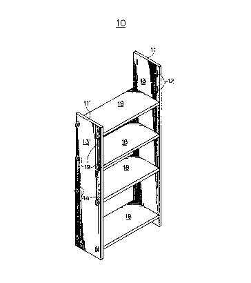
Fig. 1 is an isometric view of one unit of my modular
assembly with four (4) shelves and eight (8) shelf support
units.
Fig. 2 is a partial, reverse, exploded view of the
view depicted in Fig. 1.
Fig. 3 is an isometric, partially-exploded detail view
of a tapered peg of my invention, and its method of inser-
tion into the hole of a shelf support tab and its coopera-
tion with the outer surface of a side panel.

7 3 7
BEST MODE FOR CARRYING OUT INVENTION
Referring to the Figures, there is depicted generally
my modular shelving assembly 10. Assembly 10 has two
substantially upright, spaced-apart side panels 11 and
11'. Panels 11 and 11' have a plurality of holes 12
extending through their lateral surfaces 13 and 13'.
Here, the holes 12 are provided in pairs near the side
edges of both panels 11 and 11'. Also, a pair of holes 12
in panel 11 are provided to be at approximately equal dis-
tance from panel ll's bottom edge as a corresponding pair
of holes 12 in panel 11' are provided to be at the same
distance from its bottom edge.
Holes 12 receive tabs which extend from each end of
shelf support units 15. Tabs 14 are a region of reduced
cross-section of shelf support unit 15 at its ends. Tab
14 has a shoulder 16 where the tab meets the rest of the
shelf support unit 15. Shelf support unit 15 is here a
rectangular slat usually several feet in length, several
inches in height and a partial inch in width. The width
of slat 15 i6 provided to cooperate and fit in groove 17
in the bottom of shelf 18 so that the shelf 18 is securely
mounted on top of two slats 15 as shown in Fig. 2.
Pegs 19 in the shape of split, truncated cones extend
through holes 20 near the ends of tabs 14 on shelf units
15. The flat side surface of peg 19 cooperates and binds
with the outer lateral surface 13 or 13' of side panels 11
and 11'. The round side surface of peg 19 cooperates and
binds with the surface of hole 20. Peg 19 is sized so
that it extends partly through hole 20, but not all the
way through it, when tab 14 is extending through hole 12

21~2737
of panel 11' as shown in Fig. 3. This way, a convenient
friction fit is created between panel 11', tab hole 20 and
the flat and round side surfaces, respectively, of peg 19.
This friction fit is easily created by inserting peg 19
and tapping it gently on the back end to tighten it.
Also, this friction fit is easily eliminated by tapping
peg 19 gently on the front end to loosen it, and removing
it.
My assembly may be repeated in the parallel direction
of shelf support units and/or shelves to multiply and
extend to become a wall-length shelving unit. In this
case, a third side panel is added to create a second
assembly, and, a fourth side panel is added to create a
third assembly, etc., or n + 1 side panels for n assem-
blies. Also, my assembly may be repeated in the perpen-
dicular direction by adding an extra side panel perpendic-
ular to the first 2 panels, and then the fourth panel
parallel to the third, extra panel. Also, my assembly may
be used to connect parts of furniture besides shelving,
like bed frames and desks and tables, for example.
Also, the shelf support units and the shelves pictured
here may be provided in one piece. Or, the shelf itself
may have a tab on each end for insertion through the holes
in the side panels. In this case the shelf tabs may be
horizontal tabs wide enough in the horizontal direction to
provide adequate support for the shelf and to prevent the
shelf from tipping, or rotating, when it is secured be-
tween the two panels. The best mode of my assembly,
however, is like that depicted in the Figures.
My assembly may be made from conventional materials by
conventional techniques. I prefer a veneered wood for
panels 11 and 11', shelf support units 15 and shelves 18.
I prefer solid hardwood for pegs 19.

~1~2737
-- 5
While there is shown and described the present pre-
ferred embodiment of the invention, it is to be distinctly
understood that this invention is not limited thereto but
may be variously embodi.ed to practice within the scope of
the following claims.

Representative Drawing
A single figure which represents the drawing illustrating the invention.
Administrative Status

2024-08-01:As part of the Next Generation Patents (NGP) transition, the Canadian Patents Database (CPD) now contains a more detailed Event History, which replicates the Event Log of our new back-office solution.

Please note that "Inactive:" events refers to events no longer in use in our new back-office solution.

For a clearer understanding of the status of the application/patent presented on this page, the site Disclaimer , as well as the definitions for Patent , Event History , Maintenance Fee  and Payment History  should be consulted.

Event History

Description Date
Revocation of Agent Requirements Determined Compliant 2020-04-22
Appointment of Agent Requirements Determined Compliant 2020-04-22
Time Limit for Reversal Expired 2008-11-10
Letter Sent 2007-11-09
Inactive: IPC from MCD 2006-03-11
Grant by Issuance 1999-08-24
Inactive: Cover page published 1999-08-23
Inactive: Final fee received 1999-05-19
Pre-grant 1999-05-19
Letter Sent 1999-02-16
Notice of Allowance is Issued 1999-02-16
Inactive: Approved for allowance (AFA) 1998-07-13
Inactive: Application prosecuted on TS as of Log entry date 1997-11-21
Inactive: Status info is complete as of Log entry date 1997-11-21
All Requirements for Examination Determined Compliant 1995-08-18
Request for Examination Requirements Determined Compliant 1995-08-18
Application Published (Open to Public Inspection) 1994-06-10

Abandonment History

There is no abandonment history.

Maintenance Fee

The last payment was received on 1999-05-19

Note : If the full payment has not been received on or before the date indicated, a further fee may be required which may be one of the following

  • the reinstatement fee;
  • the late payment fee; or
  • additional fee to reverse deemed expiry.

Patent fees are adjusted on the 1st of January every year. The amounts above are the current amounts if received by December 31 of the current year.
Please refer to the CIPO Patent Fees web page to see all current fee amounts.

Fee History

Fee Type Anniversary Year Due Date Paid Date
Request for examination - small 1995-08-18
MF (application, 4th anniv.) - small 04 1997-11-10 1997-11-06
MF (application, 5th anniv.) - small 05 1998-11-09 1998-10-29
MF (application, 6th anniv.) - small 06 1999-11-09 1999-05-19
Final fee - small 1999-05-19
MF (patent, 7th anniv.) - small 2000-11-09 2000-10-25
MF (patent, 8th anniv.) - small 2001-11-09 2001-11-01
MF (patent, 9th anniv.) - small 2002-11-11 2002-10-11
MF (patent, 10th anniv.) - small 2003-11-10 2003-10-24
MF (patent, 11th anniv.) - small 2004-11-09 2004-10-06
MF (patent, 12th anniv.) - small 2005-11-09 2005-11-02
MF (patent, 13th anniv.) - small 2006-11-09 2006-11-01
Owners on Record

Note: Records showing the ownership history in alphabetical order.

Current Owners on Record
THOMAS W. GOLLICK
Past Owners on Record
None
Past Owners that do not appear in the "Owners on Record" listing will appear in other documentation within the application.
Documents

To view selected files, please enter reCAPTCHA code :


To view images, click a link in the Document Description column. To download the documents, select one or more checkboxes in the first column and then click the "Download Selected in PDF format (Zip Archive)" or the "Download Selected as Single PDF" button.

List of published and non-published patent-specific documents on the CPD .

If you have any difficulty accessing content, you can call the Client Service Centre at 1-866-997-1936 or send them an e-mail at CIPO Client Service Centre.


Document
Description 
Date
(yyyy-mm-dd) 
Number of pages   Size of Image (KB) 
Description 1995-06-09 5 258
Claims 1995-06-09 2 100
Abstract 1995-06-09 1 25
Drawings 1995-06-09 2 81
Representative drawing 1999-08-17 1 11
Commissioner's Notice - Application Found Allowable 1999-02-15 1 163
Maintenance Fee Notice 2007-12-23 1 173
Fees 2003-10-23 1 25
Correspondence 1999-05-18 2 54
Fees 2002-10-10 1 27
Fees 1998-10-28 1 34
Fees 1997-11-05 1 40
Fees 1999-05-18 1 32
Fees 2004-10-05 1 26
Fees 2005-11-01 1 26
Fees 2006-10-31 1 25
Fees 1995-08-17 1 50
Fees 1996-10-14 1 52