Note: Descriptions are shown in the official language in which they were submitted.
PKL Verpackungssysteme Gmb~
RurstraBe 5B
D - 5172 Linnich
________._________________________________________________________
JACKET FOR A LIQUID-TIG~T PACRaGING OF COMPOSITE CARDBOARD
MATERIAL FURNIS~D WITH A H~AT SEALING PLASTICS COATING AND
METHOD FOR ITS PRODUCTION
_________________________________________________________________
The invention relates to a jacket for a liquid-tight packaging of
composite material which consists of cardboard and a heat sealing
plastics coating on both sides and having a longitudinal seam
which is formed by an inner layer of the composite material,
having an outwardly folded-over, sealed-on edge strip, and an
outer layer of the composite material which is sealed externally
to the edge strip and the adjoining inner layer, with inclusion .
of the cut edge of the edge strip.
The invention also relates to a method for the production of such
a jacket, wherein prior to the folding over of the edge strip,
the composite material is pared off, and after the folding-over
to the pared side and the sealing-on of the edge strip, the outer
layer is sealed to the edge strip and the adjoining inner layer.
One difficulty in the production of jackets for a liquid-tight
packaging either from individual blanks or from a web of material
i5 the making of the longitudinal seam; due to the return forces
:
- 2 ~ 77~
of the composite material, more particularly of an aluminium-free
composite material, it is impossible to make a fold precisely
along a folding line without the composite material being
pretreated.
In one prior art method (DE 40 36 454 A1) the composite material
is removed by milling over the whole width of the ed~e strip,
except for a residual layer of cardboard and plastics coating,
whereafter the zone of removal is folded over. This kind of
method necessitates the use of special milling cutters, since
they are the only means of obtaining a stepped transition between
the unmilled and milled zones of the composite material, as is a
precondition for a precise edge.
It is also known to use a cup-shaped knife to pare the composite
material away in the zone of the edge strip and in the adjacent
zone extending beyond the folding line, whereafter a groove is
milled in the folding line. In any case, it would be impossible
to per~orm folding precisely along the provided folding line in
the absence of such a milled-in groove. This kind of production
also calls for the use of expensive tools.
It is an object of the invention to provide for a liquid-tight
packaging of composite cardboard material a jacket which has a
straight longitudinal seam and which can be produced by a less
expensive method, using less expensive tools, than in the prior
art.
- 3 -
rl-lis problem is solved according to the invention by the feature
that composite material is removed therefrom on the surface in a
narrow inn~r zone limited to the fold of the folded-over edge
strip; removal is more particularly by burning off or preferably
paring off said material.
In one method suitable for the production of such a jacket, prior
to the folding-over of the edge strip the composite material is
pared off in the zone of the fold, and following the folding-over
to the pared-off side and the sealing-on of the edge strip the
outer layer is sealed to the edge strip and the adjacent
composite material, which is removed only in a narrow zone
limited to the fold.
Removal can be performed, for example, by material being burnt
off at the surface by means of a laser beam. However, the
material is preferably removed mechanically by paring-off. The
paring operation can be particularly simply performed if a raised
bead extending along the folding line is formed, more
particularly by grooving, in the composite material and
subsequently pared off.
Preferably the paring-off is performed by means of a cup-shaped
knife while the composite material is borne against a steadying
element which engages in the groove of the grooved bead and
guides the grooved bead centrally over the cup-shaped knife. A
suitable steadying element is a grooving roller.
~ : ~
~ , ~
:- : ~
- "
- ,: ,.
'
_ 4 - ~ 77~
To further facilitate the folding operation in the folding-over
of the edge strip, following the removal material and prior to
the folding-over of the edge strip, a bead raised to the side
where removal has taken place is formed in the zone of removal.
The weakening of the composite material in a narrow zone limited
to the fold ensures that during folding-over the fold is formed
precisely along the folding line provided. The folding operation
and subsequent sealing-on cause no problems, even in the case of
a composite mat~rial having high return forces, for example, an
aluminium-free composite material. In any case, the composite
material is pared off over the whole zone of the edge strip or
therebeyond, so that it is superfluous to use expensive paring or
milling tools. The jacket can be particularly readily produced
if prior to paring the raised bead is produced, which can be
removed by the use of a cup-shaped knife, which is less expensive
than milling tools. Since the invention ensures that a straight
edge is obtained even after the folding-over of the edge strip
and the sealing-on thereof, the preconditions are satisfied for
precise production of the longitudinal seam.
The invention will now be explained in greater detail with
reference to the drawings, wherein:
Fig. 1 is a cross-section through a longitudinal seam of a
packaging, and
. . . ~ .,
igs. 2a-2g show different steps in the production of the
longitudinal seam, as regards both the technical
apparatus used and the product resulting therefrom.
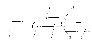
Referring to Fig. l, in a packaging jacket the composite material
used consists of cardboard and a plastics coating of heat sealing
material, for example, PE, on both sides. The weight per unit
area of the composite material is between 200 and 250 g/m2. An
inner layer 2 disposed in the zone of a longitudinal seam 1 of
the jacket overlaps with an outer layer 3 of the composite
material. An edge strip 4 of the inner layer 2 is folded over
outwardly and sealed on the outside to the inner layer 2. The
outer layer 3 is sealed to both the edge strip ~ and the
adjoining inner layer 2, with the inclusion of the cut edge of
the edge strip 4. In a fold 6 the composite material is weakened
in a narrow zone on its surface by the paring of said material.
To produce such a longitudinal seam, after the step illustrated
in Fig. 2a, a raised ~ead 8 is formed in the composite material 7
by said material 7 passing through a pair oE rollers 9a, 9b with
a negative groove and a grooving disc.
In a second method step (Fig. ~b) the composite material 7 is
supplied to a rotating cup-shaped knife 10, the composite
material 7 being supplied centrally to the cup-shaped knife 10 by
means of a roller 12 which engages in th~ groove 11 of the
composite material 7 and acts as a steadying element and guideO
... . , : ~ :
.
, . ~ .~
, .
.
~ ' .
2 ~
- 6 -
In the following method step (Fig. 2c) the composite material 7
is supplied to a further pair of rollers 13a, 13b having a groove
and a grooving wheel which form a fresh raised bead 14 on the
side of the composite material 7 where removal of material has
taken place. Said fresh bead 14 boosts the folding operation on
the already weakened composite material 7 along the folding line.
In the following method step (Fig. 2d) the edge strip 4 is folded
over by means of a folding tool having a folding-over bar 15.
Then the composite material 7 passes with the folded-over edge
strip (Fig. 2e) through another pair of rollers 16a, 16b which
perform a preliminary pressing.
For the sealing-on of the folded-over edge strip 4 (Fig. 2f) the
plastics (PE) coating is activated, so that in the next method
step (Fig. 2g) the edge strip 4 can be applied to the activated
zone of the composite material 7 in a further folding-over
station having a belt guide 18a, 18b.
Finally (Fig. 2h) the edge strip 4 is guided between a pair of
rollers l9a, l9b and pressed.
The further deformation of the composite material and the sealing
of t~e outer layer 3 to the edge strip ~ and the inner layer
are performed in conventional manner.