Note: Descriptions are shown in the official language in which they were submitted.
-1- 2in2792 PCI`/US92/03723
RECLOSABLE CARTON FOR GRANULAR MATERIALS
FiELD OF THE INVENTION
The present invention relates to carton board cartons, and more
particularly, to such cartons suitable for housing granular or
powdered materials that are reclosable and sift-resistant.
BACKGROUND INFORMATION
Reclosable carton board cartons have been available for many
years. The ability to repeatedly open and close/lock down these
cartons after initial opening have long been important goals of
those skilled in the art. One way to accomplish these goals is to
use a carton which can be opened and closed by the use of locking
flaps. Examples of these cartons are found in various United States
Patents.
One patent of particular interest is United States Patent
4,326,634 which issued to Meyers on April 27, 1982. This Patent
discloses a reclosable carton. A locking flap attached to the front
wall of the carton engages with the inner layer of the front skirt
panel enabling the carton to be repeatedly closed or locked down
after initial opening.
Existing cartons of this type, however, suffer from at least
one major drawback when used with granular or powdered materials.
They are not sift-resistant. Therefore, spillage often accompanies
transporting and opening of the carton. During transit, the
granules migrate into the spaces between the various layers and
through any cracks and crevices. For example, the granules have a
way of working themselves between the inner layer which remains
stationary and the outer layer which is moved during opening. Thus,
when the outer layer is moved as the carton is opened the granules
are left unsupported and fall. In addition, if the top and its
adjacent skirt are allowed to float, as the skirt is not fixed to
the carton walls during shipping, granules will sift over the front
.~
W 0 92/20583 2 1 0 2 7 9 2 P~/us92/o3723
-2-
and side walls. The resulting mess that is created is
unsatisfactory to consumers.
Accordingly, it is an object of the present invention to
provide a granules carton that is both reclosable and sift-
resistant;
It is further an object of the present invention to provide a
granules carton that is easy to fill, open and dispense therefrom;
It is further an object of the present invention to provide a
carton which substantially eliminates the problem of granular
contents spilling upon opening;
It is further an object of the present invention to provide
such a carton that is opened by the removal of a tear strip;
It is lastly an object of the present invention to provide a
carton that accomplishes the aforementioned objectives at minimal
costs.
SUMMARY OF THE INVENTION
In accordance with one aspect of the present invention a sift-
resistant, reclosable carton is provided for granular or powdered
materials. The carton is a six-sided enclosure having opposed top
and bottom walls, opposing front and back walls, and opposing end
walls. Each of the end walls has an inner layer with a top edge
abutting the top wall and an outer layer. The outer layer has a
horizontal tear strip thereacross. The front wall has an inner
layer with a top edge abutting the top wall and an outer layer. ~he
outer layer has a horizontal tear strip thereacross which is
integral with the tear strips of the end walls to form one
continuous tear strip. A glue flap is integrally attached to the
top edge of the inner layer of the front wall along substantially
its full length. The glue flap has a distal attachment portion and
a proximal locking portion. The two portions are joined along a
full length line of weakness. The distal attachment portion is
secured to the inner surface of the outer 1 ayer of the front wal 1
above the tear strip.
BRIEF DESCRIPTION OF THE DRAWINGS
While the specification concludes with claims which
particularly point out and distinctly claim the invention, it is
believed the present invention will be better understood from the
. . ~
WO 92/20583 2 1 0 2 7 9 2 PCI/US92/03723
-3 -
following description of preferred embodiments taken in conjunction
with the accompanying drawings, in which like reference numerals
identify identical elements and wherein;
Figure 1 is a perspective view of a preferred embodiment of the
5 present invention, prior to opening;
Figure 2 is a perspective view of the carton of Figure 1, seen
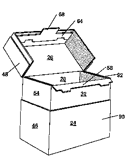
in an open condition with the top raised;
Figure 3 i s a top plan view of the blank used to make the
carton of Figure 1;
Figure 4 is a top plan view of the blank of Figure 3 after
initial folding, showing the glue application areas;
Figure 5 is a top plan view of the flattened sleeve made from
the blank of Figure 3;
Figure 6 is a perspective view of the sleeve of Figure 5 after
1~ being squared for transformation into the carton of Figure l;
Figure 7 is a cross-sectional view taken along line 7-7 of
Figure 6 showing the wall construction of the sleeve;
Figure 8 is a fragmentary cross-sectional view taken along line
8-8 of Figure 1 showing the end wall construction of the carton of
Figure l;
Figure 9 is a perspective view of a second preferred embodiment
of the present invention, prior to opening;
Figure 10 is a top plan view of the blank used to make the
carton of Figure 9;
Figure 11 is a perspective view of a sleeve formed from the
blank of Figure 10 after being squared for transformation into the
carton of Figure 9;
Figure 12 is a fragmentary cross-sectional view taken along
line 12-12 of Figure 9 showing the end wall construction of the
preferred embodiment;
Figure 13 is a perspective view of a third preferred embodiment
of the present invention, seen in an open condition with the top
raised;
Figure 14 is a perspective view of a fourth preferred
embodiment of the present invention, with the handle in the shipping
position;
WO 92/20583 PCr/US92/03723
2 1 U~7~ -4-
Figure 15 is a top plan view of the blank of the liner used in
the carton of Figure 14; and
Figure 16 is a perspective view of the embodiment of Figure 14,
seen in an open condition with the top raised and with the handle
5out of the way.
DESCRIPTION OF THE PREFERRED EMBODIMENT
In a particularly preferred embodiment seen in Figure 1, the
present invention provides a side-fill, sift-resistant, reclosable
carton, indicated generally as 20, for housing granular or powdered
10materials. The embodiment of Figure 1 is made from the blank
illustrated in Figure 3.
Referring to Figure 3, the blank incorporates five main panels
24, 26, 28, 30 and 32 which are successively connected to each other
along transverse score lines 34, 36, 38, and 40. The five main
15panels, from top to bottom, include a front outer panel 24, a top
panel 26, a back panel 28, a bottom panel 30 and a front inner panel
32. The transverse boundaries of each of these panels 24, 26, 28,
30 and 32 are defined by axial score lines 42 and 44. The axial
score lines 42 and 44 also serve to connect each panel 24, 26, 28,
2030 and 32 to an end flap 46 through 55 at each transverse edge.
The end flaps associated with the front inner panel 32 and the
back panel 28 are the major flaps 54, 55, and 50, 51. The major
flaps 50, 51, 54 and 55 preferably have substantially the same
transverse dimension as the axial dimension of the top panel 26; and
25even more preferably, have substantially the same overall dimensions
as the resulting end wall of the carton 20. The end flaps
associated with the bottom panel 30 are the minor flaps 52 and 53.
The minor flaps 52 and 53 are somewhat smaller in transverse
dimension than the major flaps 50, 51, 54 and 55. The end flaps
30associated with the top panel 26 will hereinafter be referred to as
ears 48 and 49. The transverse dimension of the ears 48 and 49 is
substantially smaller than the transverse dimension of the major
flaps 50, 51, 54 and 55.
The end flaps associated with the front outer panel 24 will
35hereinafter be referred to as extension panels 46 and 47. In this
embodiment these extension panels 46 and 47 have substantially the
same transverse dimension as the major flaps 50, 51, 54 and 55. The
WO 92/20583 2 1 0 2 7 9 2 PCT/US92/0372~
_ -5
front outer panel 24 and its associated extension panels 46 and 47
have a transverse tear strip ~6 extending thereacross. Tear strip
56 is preferably two transverse parallel lines 50% cut into the
outer side of the front outer panel 24 and extension panels 46 and
47. A 50% cut is a continuous cut which extends from the surface of
the material down to a depth which is half of the thickness of the
material. The 50% cut assures a clean tear at the surface which
leaves a relatively pleasing appearance, particularly when the
carton 20 is printed. Attached to the inner side of tear strip 56
0 is a reinforcing tape, not shown, which helps prevent the tear strip
56 from breaking into pieces as it is removed from the carton 20.
One end of the tear strip 56 extends beyond the axial edge of the
extension panel 47, providing a tab to facilitate grasping tear
strip 56.
1, A glue flap 59 comprising proximal locking portion 58 and
distal attachment portion 64 is connected to the lower transverse
edge of the front inner panel 32 via a cut score line 60. The cut
score line 60 is preferably cut deeply enough to facilitate bending
of the proximal locking portion 58 about cut score line 60 but not
so deep as to permit the proximal locking portion 58 to separate
from front inner panel 32 during repeated normal opening of the
carton 20. In addition, the cut score line 60, being a partial cut
instead of a full cut, prevents the granular material from migrating
through the cut.
7~ Proximal locking portion 58 is connected to distal attachmentportion 64 along a full length line of weakness which comprises
remotely spaced land areas 65. A pair of tabs 62 and 63 are located
along the lower transverse edge of the proximal locking portion 58
opposite a pair of matching cutouts 66 and 67 along the upper
transverse edge of distal attachment portion 64. The engagement
between tabs 62 and 63 and cutouts 66 and 67 i n use permits the
carton 20 to be repeatedly opened and locked down, as will be
discussed hereinafter.
Distal attachment portion 64 comprises an opening tab 68 along
35 its lower transverse edge. After tear strip 56 has been removed
opening tab 68 will aid the user by providing a convenient means to
open the carton 20, as will be discussed hereinafter.
2 1 1 2 7 ~ ~ PCT/US92/03723
-6-
To assemble the carton 20 the blank of Figure 3 is first folded
and glued to form the sleeve shown in Figure 5. Initially, glue
flap 59 is folded downwardly as a unit 180- about the transverse cut
score line 60 to lie against the outer side of front inner panel 32.
Glue is then applied to distal attachment portion 64. Then t
blank is folded 180 about the transverse score line 40 whi~
separates the front inner panel 32 from the bottom panel 30 to place
front inner panel 32 above bottom panel 30 and the lower portion of
back panel 28. Glue is then applied to the front outer panel 24 i n
o the two locations indicated as 74. The result of these steps is
shown in Figure 4. The blank is then folded 180 about the
transverse score line 36 which separates the top panel 26 from the
back panel 2B so that front outer panel 24 overlies glued flap 59
and inner panel 32. Thus, the distal attachment portion 64 of glue
flap 59 is adhered to the inner side of the front outer panel 24
above tear strip 56. In addition, front outer panel 24 and
extension panels 46 and 47 are adhered below the tear strip 56 to
the front inner panel 32 and the major flaps 54 and 55 associated
therewith. The finished sleeve is seen in Figure 5.
When used by the product packager, the sleeve is set up, one
end is folded and sealed, the carton 20 is filled, and then the
other end is folded and sealed. As seen in Figure 6, to set up the
carton 20 the sleeve is squared so that each of the five main panels
24, 26, 28, 30 and 32 are at substantially right angles to their
2, adjacent panels. To fold and seal one end, the minor flap 52
associated with the bottom panel 30 iS first folded 90 about the
axial score line 42 to a position perpendicular to the bottom panel
30. The major flap 50 associated with the back panel 28 is folded
90- about the axial score line 42 and preferably adhered to the end
flap 52 associated with bottom panel 30. The major flap 54
associated with the front inner panel 32 and the extension panel 46
associated with front outer panel 24, adhered thereto, are then
folded 90 about the axial score line 42 and adhered to the exterior
side of the major flap 50 of the back panel 28. Lastly, the ear 48
associated with the top wall 26 is folded 90- and adhered to the
exterior of the front outer panel 24 extension panel 46. As seen in
Figure 8, the top wall 26 ear 48 is folded over and attached such
WO 92/20583 2 I (1~ 7 9 ~ PCr/`US92/03723
-7-
that the top wall 26 is pulled down against the top edge 86 of the
major flaps 50 and 54 creating a barrier to granular movement.
The carton 20 is filled through the remaining open end with a
granular material and the other end is folded and sealed. The
5 folding and sealing operation of this end is identical to the
folding and sealing operation described above. At this point the
carton 20 is filled, sealed and ready for shipment.
Referring to Figure 1, the carton 20 is an enclosure formed by
the various panels and flaps. These panels and flaps are the
corresponding walls of the carton 20. The top 26, bottom 30, and
back 28 panels are the top 26, bottom 30, and back 28 walls,
respectively. The front wall 90 is made up of the front inner panel
32 and the front outer panel 24. The end walls 92 are made from the
remaining flaps, panels and ears. The top wall 26 opposes the
1, bottom wall 30, the front wall 32 opposes the back wall 28 and the
end walls 92 oppose each other.
The walls of the carton 20 as assembled are seen in Figures 7
and 8. Referring to Figure 8, each end wall 92 includes a total of
five layers. The innermost layer is the minor flap 52 associated
with the bottom wall 30. The second layer is the major flap 50
associated with the back wall 28. The middle and fourth layers are
the major flap 54 associated with the front inner panel 32 and the
extension panel 46 of the front outer panel 24, respectively. The
outermost layer is the ear 48 associated with the top wall 26. As
seen in the drawing, the top wall 26 is pulled tightly against the
top edge 86 of the major flaps 50 and 54. This provides a sift-
proof barrier which prevents granules from migrating during shipment
to the space between the major flap 54 associated with the front
inner panel 32 and extension panel 46 of the front outer panel 24.
If granules migrate to this area spillage will result upon opening
of the carton 20. In addition to providing a sift-proof barrier,
the major end flaps 50 and 54, being coextensive, i.e., having
substantially the same dimensions as the end wall 92, provide added
strength to the carton 20.
3 Referring to Figure 7, the front wall 90 is formed of three
layers. The layers of the front wall 90 are formed from the front
inner panel 3Z, front outer panel 24, and glue flap 59, which
W O 92/20583 2 1 0 2 7 ~ 2 PC~r/US92/03723
-8-
comprises proximal locking portion 58, distal attachment portion 64,
and opening tab 68. Front inner panel 32 and front outer panel 24
are attached to each other below the tear strip 56. Distal
attachment portion 64 is attached to front outer panel 24 above the
tear strip 56. Proximal locking portion 58 and distal attachment
portion 64 provide reinforcement for front inner panel 32. This
reinforcement of front inner panel 32 prevents migration of granules
over front inner panel 32 during shipping as the front inner panel
32 is less likely to be deformed due to the pressure applied by the
granular contents within the carton. In addition, the cut score
line 60 being a partial cut instead of a complete cut prevents the
migration of granules through the cut in the area between the front
inner panel 32 and the front outer panel 24. The cut score line 60
must be deep enough to facilitate bending of the proximal locking
portion 58 during repeated opening and closing of the carton 20, but
it must not be so deep as to permit the proximal locking portion 58
to be detached from the front inner panel 32.
To open the carton 20 the user grasps the tab of the tear strip
56 and pulls the tear strip 56 away from the carton 20. Removal of
the tear strip 56 exposes opening tab 68 to the user. The user
grasps opening tab 68 and pulls the opening tab 68 upward. This
separates the top, which includes the front outer panel 24 and
associated panel extensions 46 and 47 above the tear strip 56, the
top wall 26, the ears 48 and 49 and the distal attachment portion
64? from the remainder of the carton 20. The top is a three-sided
lid which is now free to rotate. As the lid is rotated about the
transverse score line 36, which joins the top wall 26 to the back
wall 28, the proximal locking portion 58 of glue flap 59 is
separated from the distal attachment portion 64. Rotating the lid
along this score line 36 to an open position allows access the
contents of the carton 20. As the lid is rotated proximal locking
portion 58 is pulled in an upward direction about cut score line 60
This elevation of proximal locking portion 58 returns the granular
contents that may have migrated between the proximal locking portion
3; 58 and the front outer panel 24 back into the carton where they can
be properly dispensed with little or no mess. After dispensing the
desired amount of granular products, the carton 20 may be closed by
` ` W O 92/20583 2 t 0 2 7 9 2 PC~r/US92/0372~
g
rotating the lid back to the closed position. As the lid is rotated
back to the closed position tabs 62 and 63 of proximal locking
portion 58 engage cutouts 66 and 67 of distal attachment portion 64.
When completely closed, the proximal locking portion 58 and distal
- , attachment portion 64 together hold the lid in closed condition
until it is forcibly lifted. The disengaging and engaging of
proximal locking portion 58 with distal attachment port;on 64 via
opening and closing of the carton lid can be repeated until the
contents of the carton 20 have been emptied.
A second preferred embodiment can be seen in Figure 9. This
second embodiment is made from the blank of Figure 10. The blank of
Figure 10 is virtually identical to the blank of Figure 3. The only
difference is that the ears 148 and 149 extend from the extension
panels 146 and 147 of front outer panel 124 along transverse score
lj line 134 rather than from the top panel 126. The top panel 126 has
no end flaps attached to its axial edges. As seen in Figure 9, this
blank results in a carton 120 having the ears 148 and 149 attached
to the top wall 126.
This blank is folded and glued into the sleeve configuration
for shipment to the product packager as the previous embodiment.
Upon receipt by the packager the carton 120 is squared as seen in
Figure 11. Folding and sealing the ends requires a slightly
different operation, however, than the previous embodiment. As
described before, the bottom panel 130 minor flap 152, the back
panel 128 major flap 150, and then the front inner panel 132 major
flap 154 and the front outer panel 124 extension panel 146 are
sequentially folded 90- and glued to the adjacent flaps. Then the
ear 148, which is connected to the extension panel 146 of front
outer panel 124, is folded about the score line 134 and glued to the
top wall 126. This last step is done such that the top panel 126 is
pressed tightly against the top edge 186 of the major flaps 150 and
154 creating a sift proof barrier. The same operation is followed
to seal the other end of the carton 120.
Referring to Figure 12, the carton 120 of Figure 9 is shown in
cross section. Each end wall consists of four layers. The
innermost layer is the bottom panel 130 minor flap 152. The next
layers are the back wall 128 major flap 150 followed by the major
W O 92/20583~ 2 1 0 2 7 9 2 PCT/US92/03723
-10-
flap 154 of front outer panel 132 . The outer most layer is the
extension panel 146 associated with front outer panel 124. The top
wall 126 has the ear 148 attached thereto. The ear 148 is connected
along the score line 134 to~ the tear strip extension panel 146.
A third preferred embodiment can be seen in Figure 13. The
carton of Figure 13 is virtually identical to the cartons of Figures
1 and 9 and their respective blanks shown in Figures 3 and 10. The
only difference is that proximal locking portion 258 and
corresponding distal attachment portion 264 of glue flap 59 contain
no tabs and corresponding cutouts.
A fourth preferred embodiment, shown in Figure 14, provides a
carton indicated generally as 320, with a handle 370, the carton
being adapted for housing granular or powdered materials. The
embodiment shown in Figure 14, is similar to the carton disclosed in
commonly assigned U.S. Patent 4,986,420 issued to Gunn et al. on
January 22, 1991, the description of the general structure of such
carton being hereby incorporated by reference herein.
Referring to Figure 15 there is shown the blank for the
improved paperboard liner 380 of this embodiment. It has five
segments 383, 384, 385, 386 and 387 separated by four axial score
lines 388, 389, 390 and 391, which can be perforated lines.
Embossed areas 392 are preferably located on the liner 380 (although
it may be in the outer carton body as well) such that when the
carton 320 is assembled, filled and sealed, they will create a thin
.5 cavity between the liner 380 and the outer body 318 adjacent the
area immediately surrounding the apertures 364 in the outer body
318.
A glue flap 459 comprising proximal locking portion 458 and
distal attachment portion 464 is connected to segment 384 via cut
score line 460. The cut score line 460 is preferably cut deeply
enough to facilitate bending of the proximal locking portion 458
about cut score l ine 460 but not so deep as to permit the proximal
locking portion 458 to separate from segment 384 during repeated
normal opening of the carton 320. Cut score line 460, being a
3 partial cut instead of a full cut, prevents the granular material
from migrating through the cut.
WO 92/20583 PCr/US92/03723
21 02792
Proximal locking portion 458 is connected to distal attachment
portion 464 along a full length line of weakness which comprises
remotely spaced land areas 465. A pair of tabs 462 and 463 are
located along the full length line of weakness opposite a pair of
matching cutouts 466 and 467. The engagement between tabs 462 and
463 and cutouts 466 and 467 in use permits the carton 320 to be
repeatedly opened and locked down, as will be discussed hereinafter.
Referring to Figure 14, the result is an assembled carton 320
filled with granular material. The carton 320 has a top wall, a
bottom wall, a front wall, a back wall and a pair of opposing end
walls. Referring to Figure 16, the front, back and end walls
consists of an inner and outer layer. The inner layer comprises
liner 380 and the outer layer comprises outer body 318. Proximal
locking portion 458 and distal attachment portion 464 of glue flap
459 provide reinforcement for the front inner layer. This
reinforcement of the front inner layer prevents migration of
granules over the front inner layer during shipping as the front
inner layer is less likely to be deformed due to the pressure
applied by the granular contents within the carton. Each end wall
has an aperture 364 therein. The liner 380 serves to prevent the
flow of the granular contents out through the apertures 364. The
liner 380 is located adjacent the apertures 364, separating the
contents of the carton 320 from the area immediately surrounding the
apertures 364.
To open the carton 320 the user rotates the handle 370 down
toward either the front or the back of the carton 320 and grasps tab
349 of the tear strip 348 and removes the tear strip 348, seen in
Figure 14. The user rotates the lid which is connected to the back
wall by a hinge line to the open position, seen in Figure 16. As
the lid is rotated about the hinge, the proximal locking portion 458
is separated from the distal attachment portion 464 and proximal
locking portion 4S8 is pulled in an upward direction about cut score
line 460. The elevation of proximal locking portion 458 returns the
granular contents that may have migrated between the proximal
locking portion 458 and the outer body 318 back into the carton
where they can be properly dispensed. After dispensing the desired
amount of granular product, the carton 320 may be closed by rotating
W o 92/20583 210 2 7 9 ~ PCT/US92/03723
-12-
the lid back to the closed position about the hinge. As the lid is
rotated back to the closed position tabs 462 and 463 engage cutouts
466 and 467. When completely closed, the proximal locking portion
458 and distal attachment portion 464 together hold the lid in
s closed condition until it is forcibly lifted. The disengaging and
engaging of proximal locking portion 458 with distal attachment
portion 464 via opening and closing of the carton lid can be
repeated until the contents of the carton 320 have been emptied.
Although particular embodiments of the present invention have
lo been shown and described, modification may be made to the carton
without departing from the teachings of the present invention. The
terms used in describing the invention are used in their descriptive
sense and not as terms of limitation, it being intended that all
equivalents thereof be included within the scope of the appended
claims.