Language selection

Search

Patent 2102874 Summary

Third-party information liability

Some of the information on this Web page has been provided by external sources. The Government of Canada is not responsible for the accuracy, reliability or currency of the information supplied by external sources. Users wishing to rely upon this information should consult directly with the source of the information. Content provided by external sources is not subject to official languages, privacy and accessibility requirements.

Claims and Abstract availability

Any discrepancies in the text and image of the Claims and Abstract are due to differing posting times. Text of the Claims and Abstract are posted:

  • At the time the application is open to public inspection;
  • At the time of issue of the patent (grant).
(12) Patent Application: (11) CA 2102874
(54) English Title: DEVICE FOR JOINING FILMS OF HEAT-SHRINKABLE PLASTIC MATERIAL IN A MACHINE USING SAID FILM
(54) French Title: DISPOSITIF POUR REUNIR DES PELLICULES EN MATERIAU PLASTIQUE THERMORETRACTABLE DANS UNE MACHINE UTILISANT CES PELLICULES
Status: Deemed Abandoned and Beyond the Period of Reinstatement - Pending Response to Notice of Disregarded Communication
Bibliographic Data
(51) International Patent Classification (IPC):
  • B29C 65/18 (2006.01)
  • B29C 35/16 (2006.01)
  • B29C 65/00 (2006.01)
  • B65H 19/18 (2006.01)
(72) Inventors :
  • GATTESCHI, EMANUELE (Italy)
(73) Owners :
  • OCME S.R.L.
(71) Applicants :
  • OCME S.R.L. (Italy)
(74) Agent: MARKS & CLERK
(74) Associate agent:
(45) Issued:
(22) Filed Date: 1993-11-10
(41) Open to Public Inspection: 1994-05-12
Examination requested: 2000-08-15
Availability of licence: N/A
Dedicated to the Public: N/A
(25) Language of filing: English

Patent Cooperation Treaty (PCT): No

(30) Application Priority Data:
Application No. Country/Territory Date
MI 92 U 000978 (Italy) 1992-11-11

Abstracts

English Abstract


Abstract
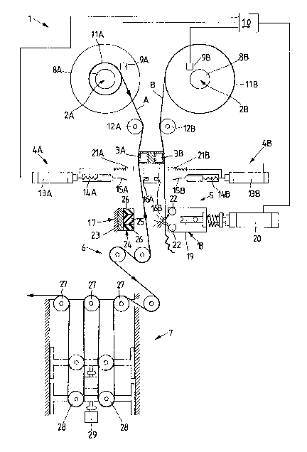
In order to make it possible the bobbin (11A) of
heat-shrinkable plastic material film to be replaced
without stopping the machine which uses it, the device
(1) substantially comprises, listed in the direction
of film (A-B) unwinding, one pair of parallel reels
(2A, 2B), respectively supporting the bobbins (11A,
11B) on which the film (A-B) is wound, two sucking
mouths (3A, 3B), two cutting devices (4A, 4B), a
welding device (6) and an accumulation device (7).


Claims

Note: Claims are shown in the official language in which they were submitted.

THE EMBODIMENTS OF THE INVENTION IN WHICH AN EXCLUSIVE
PROPERTY OR PRIVILEGE IS CLAIMED ARE DEFINED AS FOLLOWS:
1. Device (1) for automatically joining films
(A-B) of heat-shrinkable plastic material in a machine
using said film, characterized in that said device
substantially comprises, listed in the direction of
film unwinding:
-- one pair of reels (2A, 2B) with parallel axes,
suitable for respectively housing a first bobbin
(11A) of heat-shrinkable film from which said film
(A) is being unwound, and a second bobbin (11B)
which is in stand-by step and is ready to supply
the film (B) as soon as the first bobbin (11A) gets
emptied,
-- one pair of sucking devices (3A, 3B), acting on the
whole width of films (A, B) and suitable for
keeping the film (A) coming from the first bobbin
(11A) and the film (B) coming from the second
bobbin (11B) independently clamped by means of
their sucking action;
-- one pair of cutting devices (4A, 4B), each of which
is capable of independently acting on either of
both films (A, B),
-- a welding device (5) suitable for simultaneously
acting on both films (A, B),
-- an accumulator device (7) for accumulating the film
which is being unwound,
-- means (9A, 9B) for detecting the emptying degree of
bobbins (11A, 11B), connected with a central
control unit (10) capable of commanding, according
to a pre-established operating cycle, the operation

of the sucking devices (3A, 3B), cutting devices
(4A, 4B), welding device (5) and reels (2A, 2B).
2. Device according to claim 1, characterized in
that each cutting device (4A, 4B) comprises a pressing
element (21A, 21B) elastically acting on the film (A,
B), so as to keep it blocked in the nearby of the line
of action of the cutting blade.
3. Device according to claim 1, characterized in
that the welding device (5) comprises:
-- an actuator device (20), a pressing element (18), a
welder bar (19) and a stationary shoulder (23), in
which the actuator cylinder (20) simultaneously
acts: elastically on the pressing element (18); and
rigidly on the welder bar (19) contained inside the
interior of said pressing element (18),
-- the pressing element (18) is provided with air
blowing nozzles (22) for blowing air for welded
joint cooling,
-- the stationary shoulder (17) is formed by a support
(23) of rigid material and a layered portion (24)
provided with a plurality of mutually overlapped
layers of elastically yielding material.
4. Device according to claim 3, characterized in
that the layered portion (24) is subdivided into two
side portions (26) identical to each other and a
central portion (25) which comprises, listed from
outside inwards, a Teflon(R) layer, at least one layer
of heat resistant silicone rubber, and at least one
layer of soft rubber,
-- the side portions (26) comprise, listed from
outside inwards, at least one layer of soft rubber.

Description

Note: Descriptions are shown in the official language in which they were submitted.


- ` 2 '~ t~
1.
"DEVICE FOR JOINING FILMS OF HEAT-SHRINKABLE PLASTIC
MATERIAL IN A MACHINE USING SAID FILM"
The present invention relates to a device for
joining heat-shrinkable fil~ in a machine using said
film.
In the presently used packaging machine, the film
of hea~-shrinkable plastic material is taken from a
bobbin ~hich, when is emptied, must be replaced ~ith a
full bobbin.
The replacement operation furthermore requires
that the trailing end of the film ~hich is being
unwound from the empty bobbin is joined (heat-welcled)
to the leading end of film coming from the 1ull
bobbin.
During the above operations, the packaging
machine has to be stopped and therefore the prod~ction
is penalized by a dead time which, on the contrary,
should desirably be avoided.
The purpose of the present finding is of
obviating the above ~èntioned drawback, i.e.,
providing a device for heat-shrinkable film joining
which is capable of making i~ possible the empty
bobbin to be repLaced by a full bobbin and the fiLm
joining to be carried out without that the machine has
to be stopped.
Such purposes are achieved by means of a device
according to claim 1.
The finding is illustrated~ for merely
exemplifying, non-limitative purposes~ in the fi~ures
of the accompanying dra~ing tables.
. . , ~ . ..

2 ~ 7 ~ :
Figure 1 is a schematic view of a device
according to the present finding, during the normal
fiLm unwinding step;
Figure 2 is a schematic view of the device
according to Figure 1, in which the pressing eLe~ent
keeps the film coming from the full bobbin and the
fiLm coming from the bobbin which is going to be
emptied pressed towards each other, stopping the
Latter immediately before the intervention of the
weLder bar;
Figure 3 is a schematic view of the device
according to Figure 1, in which the cutting device is
operating on the fiLm coming from the bobbin which is
being emptied;
Figure 4 is a schematic view of the device of
Figure 1, in which the device according to the present
finding has ended operating and the film is being
nor~aLly unwound from the repLaced bobbin.
Referring to the above mentioned figures, the
device for film joining according to the present
finding, generaLLy indicated with (1~, comprises,
listed in the direction oF unwinding of both films tA3
and (B), a first unwinding reel (2A) and a second
unwinding reel (2B), first return rollers (12A) and
~12B), a first sucking mouth ~3A) and a second sucking
~outh (3B), and a first cutting device (4A) and a
second cutting device (4B)~ a weld;ng device (5), a
set of second return rolLers (6~, and a film
accumulation device (7).
The unwinding reels (2A) and (2B) are eaeh
:~. .

associated with respective brakes (8A) and (8B) and
sensors (9A) and (9B). The sensors (9A) and (9B) send
their signals to a central control unit (10) suitable
for commanding, according to a pre-established
operating cycle, the operation of the device (1). By
means of brakes (8A) and (8B), the unit (10) can
control the unwinding speed and/or the tension both
films (A) and (B) are subject to.
The reels (2A) and (2B) support bobbins (11A) and
(11B), which, ;n the herein exemplified case, are,
respectively, close to get emptied and full. The first
return rollers (12A) and (12B) cooperate ~ith the
second return rollers (6) in such a ~ay that the
portions of film (A) and film (B~, when unwound,
result to be taut and adhering to the sucking mouths
(3A) and ~3B), which, ho~ever, do not operate
simultaneously. The firs~ and the second cutting
devices (4A) and (4B), respectively, are identical to
each other and substantially comprise actuator
sylinders (13A) and (13B~ acting by means of the
interposition of springs (14A) and~ respec~ively,
t14B) and blades (15A), and, respectively, (15B).
~ t the cutting time, the blades ~15A), (15B)
penetrate respective seats (1$A) and (16B) of a
shoulder element. The cuttin~ devices furthermore
comprise pressing elements (21A), (21B) elastisalLy
acting on films (A) and (B) so as to keep them clamped
in the nearby of the action line of blades (15A),
t15B).
The welding device t5) comprises a stationary
''~ '. ' ', ' : ' ' ' ` " ~ '
. :. :.:'~ :,: :

" 4
shoulder t17), a pressing element (18), a welder bar
t19) and an actuator cylinder (20)
The pressing element t18), which has a width
equal to the width of fi lms (A) and (8) is elastically
installed on the actuator cylinder (20) and bears a
plurality of nozzles (22) from which cooling air is
blown
On the contrary, the ~eLder bar, which also has a
width equaL to the width of films (A) and (B)o is
rigidly mounted on the stem of the actuator cylinder
(20).
The stationary shoulder (17) is formed by a
support of rigid material (23) and a layered portion
(24) consisting of a plurality of mutually overlapped
layers of elastically yielding material.
In order to favour the operating effectiveness OT
the welder bar (19), the layered portion (24) is
subdivided into a central portion (25) and two
mutually identical side portions (26), which are
layered according to a different pattern and as a
~unction of the fact that the side portions (26) are
destined to act as shoulders for the pressing element
(18) tcold)~ whilst the central portion is destined ~o
act as a shoulder for the ~elder bar t19) thot).
The side portions t26~ comprise, listed from
outside inwards, at least one layer of soft, however
not necessarily heat-resistant, rubber.
The central portion (25) comprises, listed from
outside inw3rds, a Teflon(R) layer, at least one layer
of heat-resistant 5i licone rubber and at least one
:
,
.~..

sof~ rubber layer.
The accumulator device t7) is of the type
comprising a first set of stationary rollers (27) and
a second set of sliding rollers ~28), which can so
slide as to move away from, while remaining coplanar
with, the above stationary rollers, under the action
of a constant force which can be applied either by a
~Jeight t29), or a hydraulic actuator, not shown in the
: .
drawings~
The larger the distance between both roller sets,
i.e., the stationary and the sliding roller sets, the
l3rger the amount of accumulated film
During the operation, the film (A) is fed to the
user machine from the bobbin (11A) which is going to
get emptied (Figure 1). The film tA) path is between
the various elements of the device, clearly visible in
Figure 1.
The bobbin t~1B) is stationary, in stand-by step.
The leading end of the film tB) lays freely
overhanging beyond the welding device, get clamped by
the depressure generated by the sucking mouth (3B).
When the sensor (9A) sends to unit (10) the
signal that the bobbin t11A~ is close to get emp~ied,
the brakes (8A) and ~8B) are enabl~ in order to block
films (A) and ~B).
The film tA), which continues to be pulled by the
packaging machine, is supplied by the accumulation
device (7), thanks to rollers (28) progressively
moving towards rollers (27).
The welding device (5) is enabled (Figure 2). The
- :

~ 7L~
6.
pressing element (18) eLastically compresses the fiLm
IB) head against the end portion of film ~A).
SubsequentLy, the welder bar presses both films (A)
and (B) against each other for the necessary time, in
order to weld the~ along at least one seaming line.
The cutting device t4A) is enabled, thus cutting
the film ~A) (Figure 3).
The free end of the portion of film (A) stilL
~ound of bobbin (11A) is clamped by the sucking ~outh
(3A) enabled at the time of disabling of the sucking
mouth (3B). The enabling of the cutting device (4A),
of the sucking mouth (3A) and the disabling of the
sucking mouth (3B) preferably take place at the same
time.
When the necessary time to carry out the welcling
has elapsed, the welder bar (9), and consequently,
also the pressing element (18), are moved back~ards.
Simultaneously~ from nozzles (22) air is blown in
order to cooL the welded seam.
The pressing element (18) is ~oved back~ards,
releasing the film (B), which can start again to
freely unwind from bobbir, (11B).
The accumulation device (7) makes it possible the
fiLm supplied soon before the future bobbin
repLacement, to be recovered.
Simultaneously, the operator, possibLy ~arned by
the same machine, removes from reeL (2A) the bobbin
(11A) and replaces it with a fuLL bobbin.
The leading end of ~he film wound on said full
bobbin ~ill be arranged as dispLayed in Figure 4,
~ ;
~:

i~e., clamped in stand-by position by the sucking
mouth t3A) ,-
The next bobbin replacement will involve the
bobbin t11B), and also it, like all preceding and
subsequent replacements, ~ill be carried out without
that stopping the machine is necessary.
. :: . : . ::, . .
, ~: ~ . . : . ,
: : ~ ' . .

Representative Drawing
A single figure which represents the drawing illustrating the invention.
Administrative Status

2024-08-01:As part of the Next Generation Patents (NGP) transition, the Canadian Patents Database (CPD) now contains a more detailed Event History, which replicates the Event Log of our new back-office solution.

Please note that "Inactive:" events refers to events no longer in use in our new back-office solution.

For a clearer understanding of the status of the application/patent presented on this page, the site Disclaimer , as well as the definitions for Patent , Event History , Maintenance Fee  and Payment History  should be consulted.

Event History

Description Date
Inactive: IPC from MCD 2006-03-11
Application Not Reinstated by Deadline 2004-11-10
Time Limit for Reversal Expired 2004-11-10
Inactive: Abandoned - No reply to s.30(2) Rules requisition 2004-03-24
Deemed Abandoned - Failure to Respond to Maintenance Fee Notice 2003-11-10
Inactive: S.30(2) Rules - Examiner requisition 2003-09-24
Amendment Received - Voluntary Amendment 2001-02-12
Letter Sent 2000-09-22
Inactive: Status info is complete as of Log entry date 2000-09-22
Inactive: Application prosecuted on TS as of Log entry date 2000-09-22
All Requirements for Examination Determined Compliant 2000-08-15
Request for Examination Requirements Determined Compliant 2000-08-15
Application Published (Open to Public Inspection) 1994-05-12

Abandonment History

Abandonment Date Reason Reinstatement Date
2003-11-10

Maintenance Fee

The last payment was received on 2002-10-28

Note : If the full payment has not been received on or before the date indicated, a further fee may be required which may be one of the following

  • the reinstatement fee;
  • the late payment fee; or
  • additional fee to reverse deemed expiry.

Please refer to the CIPO Patent Fees web page to see all current fee amounts.

Fee History

Fee Type Anniversary Year Due Date Paid Date
MF (application, 4th anniv.) - standard 04 1997-11-10 1997-10-20
MF (application, 5th anniv.) - standard 05 1998-11-10 1998-10-20
MF (application, 6th anniv.) - standard 06 1999-11-10 1999-10-28
Request for examination - standard 2000-08-15
MF (application, 7th anniv.) - standard 07 2000-11-10 2000-10-26
MF (application, 8th anniv.) - standard 08 2001-11-13 2001-11-02
MF (application, 9th anniv.) - standard 09 2002-11-11 2002-10-28
Owners on Record

Note: Records showing the ownership history in alphabetical order.

Current Owners on Record
OCME S.R.L.
Past Owners on Record
EMANUELE GATTESCHI
Past Owners that do not appear in the "Owners on Record" listing will appear in other documentation within the application.
Documents

To view selected files, please enter reCAPTCHA code :


To view images, click a link in the Document Description column. To download the documents, select one or more checkboxes in the first column and then click the "Download Selected in PDF format (Zip Archive)" or the "Download Selected as Single PDF" button.

List of published and non-published patent-specific documents on the CPD .

If you have any difficulty accessing content, you can call the Client Service Centre at 1-866-997-1936 or send them an e-mail at CIPO Client Service Centre.


Document
Description 
Date
(yyyy-mm-dd) 
Number of pages   Size of Image (KB) 
Representative drawing 1998-08-17 1 24
Claims 1995-05-13 2 72
Description 1995-05-13 7 195
Abstract 1995-05-13 1 15
Cover Page 1995-05-13 1 32
Drawings 1995-05-13 4 125
Reminder - Request for Examination 2000-07-11 1 115
Acknowledgement of Request for Examination 2000-09-22 1 178
Courtesy - Abandonment Letter (Maintenance Fee) 2004-01-05 1 177
Courtesy - Abandonment Letter (R30(2)) 2004-06-02 1 167
Fees 1996-10-23 1 73
Fees 1995-10-18 1 69