Note: Descriptions are shown in the official language in which they were submitted.
-1- 21~'~0X~
This invention relates to an improved attachment
member for a conveyor chain and trolley assembly employed ln
endless chain conveyors.
A conventional conveyor chain is formed by alterna-
tive center links and pairs of side bars connected together by
chain pins, and each center link has an open central position
defined by a pair of parallel sides and arcuate ends, the
parallel sides extending longitudinally and being spaced apart
transversely of the chain. A trolley consists of a pair of
brackets each having an arm to which a wheel is attached and a
base insertable in the open central portion of a center link.
Locating means! such as channel-shaped grooves on the trolley
bracket bases, engage the sides of the center link when an at-
tachment member is inserted between and connected to the
trolley bracket bases. -
The present invention provides an attachment member
for securing a pair of trolley bracket bases, having opposite
longitudinally spaced ends, to a conveyor chain center link
having an open central portion defined by a pair of parallel
longitudinal extending transversely spaced sides and arcuate ~:
ends, the trolley bracket bases being insertable through the
open central portion of the center link and having means for
engagement with the center link sides. The attachment member
comprises a stem portion insertable in the open central por-
tion of the center llnk between the pair of trolley bracket
ba~es for positioning said engagement means in engagement with
.
21 03~88
--2--
the center link sldQs. The ~tt~chment member further comprls-
es a psir of end portions formed lntegrally with the stem
portlon and spacQd apart longitudinally a distance greater
than the distance between the opposite ends of the trolley
bracket bases. ~hese end portions pro~ect transversely to
each side of the stem portion into overlapping relation with
the ends of the trolley bracket bases.
Each of the end portions have a T-shaped transverse
configuration formed by a leg and a head extending transverse-
ly to each side thereof, the leg being insertable between the
sides of the center link, and the head having shoulders over-
lappingly engageable with the sides of the center link at a
transition to an increase in the depth thereof. Preferably,
the head has an end face which forms a buffer for an end of
one of a pair of chain side bars connected to the center link;
and, the leg is provided with a continuation of the end face - -~
adapted to project from the open central portion of the center ~ ~-
link and form a buffer for an end of the other of the pair of ;~
chain side bars.
Another preferred feature is that the heads of the
end portions of the attachment member include pro~ections
extending toward each other into overlapping relation with
surfaces of the trolley bracket bases which intersect the end
faces thereof, and which are preferably obliquely converging
surfaces engageable by correspondingly oblique locating faces
on the pro~ections of the heads.
The attachment member of the invention is preferably
formed of an impact resistant, noise suppressing material such
_3- 2103088
as nylon. When such an attachment member 1~ lnserted between
and connected to a pair of trolley bracket bases located in
the open central portion of a chain center llnk, the opposite
ends of the bases are enclosed by the end portionc of the
attachment member, the center link sides are overlappingly
engaged by the heads of the end portions, and the end faces of
the end portions act as buffers for pairs of chain side bars
connected to the center link. The attachment member thereby
acts to limit relative longitudinal movement between the
trolley bracket bases and the center link, between the center
link and pairs of side bars connected thereto; and, to sup- - --
press the noise resulting from such relative movements.
Other features and advantages of the invention will
appear from the description to follow of the embodiment shown
in the accompanying drawings.
FIG. 1 is a side elevation showing a conveyor trolley -
connected to a center link of a conveyor chain by the attach- -
ment member of the invention;
FIG. 2 is a top plan view of FIG. 1, the wheel supporting
portion of the trolley being omitted;
FIG. 3 is a sectional elevation taken substantially as
indicated by the line 3-3 of FIG. l;
FIG. 4 is a side elevation of the attachment member of
the invention;
FIG. 5 i9 a plan view taken as indicated by the arrows S-
5 of FIG. 4; and
FIG. 6 is an end elevation of the attachment member of
FIG. 4.
~ "," '""~
_4_ 21030~8
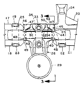
FXGS. 1-3 ~llu~trate a conveyor chaln and trolley assem-
bly incorporating an attachment member 10 of the pre~ent
invention. The conveyor chaln includes a center llnk 12
having an open central portion 14 deflned by a pair of paral-
lel sides 15 and arcuate ends 16, a pair of slde bars 17 and
18 connected to one end of the center link 12 by a chain pins
19, and another pair of side bars 20 and 21 connected to the
other end of the center link 12 by a pin 22 forming part of
the side bar 20 which includes a projecting pusher 24. The
pusher 24 is engageable with dogs of a load carrier (not -~
shown) as in a conventional power and free type of conveyor. ~-
As shown in FIG. 1, side bar engaging portions 25 of the
center link 12 adjacent to the ends thereof have an increased ~ .
depth for retaining the chain pin heads 23 in engagement with -
the side bars. ~-
The trolley consists of a pair of trolley ~:
brackets 26 each having an arm 28 to which a wheel 29 is
attached, and a base 30 which is insertable through the open
central portion 14 of the center link 12. Locating means, ---
such as channel-shaped grooves 32 (FIG. 3) on the bases 30 are :
engageable with the center link sides 15 when the attachment -:-~
member 10 is inserted between and connected to the bases 30 by ~;
bolts 33. :-~
Referring to FIGS. 4-6, the attachment member 10
comprises a stem portion 34 having parallel, oppositely facing
side surfaces 36. The stem portlon 34 ls insertable in the
open central portion 14 of the center link 12 with the side
surfaces 36 extending parallel to the center link sides 15
21030~8
--5--
betwoen the trolley brac~et bases 30, thereby po~ltlonlng
thelr locating groove~ 32 ln engagement wlth the center link
qides 15 as shown in FIGS. 1-3.
Formed integrally with the stem portlon 34 ls a palr
of end portions 38 whlch are spaced apart longitudinally a
distance greater than the distance between the opposite end
faces 40 of the trolley bracket bases 30. Each of the end
portions 38 projects transversely to either side of the stem
portion, outwardly of the side surfaces 36, and i~ position- -
able in overlapping relation with one pair of the end faces
40. ~ -
Each of the end portions 38 has a transverse ~-
shaped configuration (FIG. 6) formed by a leg 42 and a head 43
having shoulders 44 extending transversely to either side of
the leg 42. The leg 42, as best shown in FIG. 3 is insertable
between and is engageable with the sides 15 of the center link
12; the head shoulders 44 are overlappingly engageable with
the center link sides 15 at the transition where their depth
increaseq to the side bar engaging portions 25 of the center
link. The head 43 also has an end face 46 which forms a
buffer for an end 47 of one side bar of a pair of the side
bars connected to the center link 12, i.e., either the side
bar 17 or the side bar 20. The leg 42 preferably pro~ects
from the open central portion 14 of the center link 12 and has
a continuation 48 of the end face 46, which continuation end
face 48 forms a buffer for an end 49 of the other side bar of
a pair, i.e., the side bar 18 or the side bar 21.
The headq 43 of the attachment member 10 include
-6~ 21030~
pro~ectlons or caps 50 whlch extend toward each other ~nd
whlch are provided with obllquely converg~ng locatlng ~aces
52. As best shown ln FIG. 1, these pro~ectlons extend into
overlapplng relatlon with surfaces 54 of the trolley bracket
bases 30 intersecting the end faces 40, the surfaces 54 belng
obliquely converglng and engageable by the correspondingly
oblique locating faces 52. Such engagement aids in aligning
fastener receiving apertures 56 provided on the stem portion - - --
34 of the attachment member with corresponding apertures of
the trolley bracket bases for insertion of the bolts 33.
The attachment member 10 is preferably injection
molded of a suitable plastic material, e.g., nylon, having
impact resistance and sound deadening or noise suppressing
properties. An attachment member 10, made of such a material
and used in the conveyor chain and trolley assembly of FIGS.
1-3, results in important advantages. Relative longitudinal
movement between the center link 12 and the trolley brackets -- -~
26 is limited by the engagement of the shoulders 44 of the
attachment member with the center link sides at their transi-
tions to the increased depth of the side bar engaging portions ~ ~-
25, as best shown in FI~. 1. Relative longitudinal movement
between the center link 12 and the side bars 17, 18 and 20, 21
connected thereto is limited by the buffers provided by the
end faces 46, 48 of the attachment member, and contact between
the side bar ends and the trolley brackets is prevented. The
no~se that would ordlnarlly be produced by such relative
movements ls suppressed by the plastic material -- a result
that i~ becoming increasingly desired.