Note: Descriptions are shown in the official language in which they were submitted.
WO 92/2U6~U PCT/GB92/OU895
S ~~1DB'
This invention relates ~a glass'feeders'and, in
particular, to feeder arrangements for feeding molten
glass from a ~ux~nace f~rehearth to one or more processing
statiana wise=e the molten glas:a is converted into useful
objects, far example, bottles and jars.
zn the-production of glass obj~cts,'particularly the mass
1:0 production ref bottles andjars, on a continuous bas~.s, is
is,of cbnsiderable importance t~ be able t~ control the
chasa~tera.stics of the glass as it leaves the, furnace and
mores towards an appropriate fo~mi.ng unit, for example an
independent section container forming machine of known
15 ty~;~ ,
Tt is well appz~ciated that major problems can arise in
tads ~f consistency of man~factur~e if great care is not
taken ~~_operate wader homogeneous and effecbively
20 invariant condition. the problem, however; is that the
at~taa.n~nent 'of such con~.itions is particularly difficult
to achieve:
Conventionally, glass is maraufactuges3 by charging the raw
VNO 92/20630 ~ ~ ~ ~ ~ ~ ~ P~'/GB92/00895
- 2 -
materials into one end of an essentially elongate furnace
while applying heat, for example from oil burners, to
heat the raw materials and fuse them together to form a
glassy mass. The glassy mass moves away from the
ingredient feed point, down the furnace, gradually
becoming more and more homogeneous. It then flows, very
slowly since it is very viscous, into a number of
channels, perhaps as many as six ar eight in a large
furnace, known as forehearths and at the end of each
channel there is located in the floor of the channel an
aperture through which molten glass is discharged.
By ensuring a sufficient length of forehearth, and by
applying appropriate insulation and/or heating, it is
possible to ensure that, by the tinne the glass reaches
the end of the forehearth and is ready for discharge, it
is relatively free of bubbles and has a relatively stable
internal pattern of ~emperature'and viscosity. It is
not, however, easy to ensure that discharge from the
~ foreh~arth i.s always even.
A m~jor~ problem irises from tl~e fact that the glass, when
discharged, mtast be in a highly v~.scous state, so that .it
may be m~ulded and, at the sage time, cooled ~udh that ~s
2~ it is x~oulded to its final shape, it has cooled to a
emper~tur~ at vrhich it i.s'effectively sufficiently rigid
to maintain that shape during subsequent cooling and
annealing steps: Because the glass on discharge t~ the
I forehea~th~ is highly viscc~usP and because, in any event,
it mov~s~very slowly, attezapts to control the precise
temperature and homogeneity of the emergent glass are
fraught with difficulty.
In order to be able to control the overall flow of glass
WC> 92/20630 , , , . PGT/GB92/00~95
- 3 -
from the forehearth, it is a known practice to provide
located above the aperture or apertures in the forehearth
through which molten glass may pass, a metering cylinder
which may be lowered on to the forehearth floor to
~ prevent glass flow, and may be raised to permit glass to
flow under its edge and through the aperture or apertures
in the forehearth floor. In operation, such a cylinder
may be rotated about its axis when it has been raised a
little way from the forehearth fl~aor, and such rotation
can assist in homogenising the glass, but only to a
limited eXtent. Alternatively, the cylinder may be
stationary, and other stirring members moved in the glass
to promote an homogeneous glass condition within the
regi~n above the aperture(s)o Actual discharge of the
molten glass thraugh the aperture is-conventionally
achieved by the use of one or more vertically
reciprocating plungers above the apertures) which aat to
form successive gobs of glass below the aperture which
are cut off by synchronised shears-to fall into a chute
and be transported to a fornning station.
Such a system is disclosed, for example, in US 3 133 803,
and, in addition, in that case flow may bs adjusted by
the use of a-vertically-adjustable s3ca~mmer block set in
2'~ the roof of the forehearth and eahich acts as a gate under
which molten glass fl~va~s before running across a shallow
land and down an inclined wall set tp one side of a well
into which th~;glass then flows and-which surrounds the
metea~ing.cylinder anal gob plunger, and in which a shallow
34 layer ~f~molten glass f~rms. The gl~s~ is spreadout in
an attempt to render it m~re easily heate,ble or conlable,
but such spreading out leads td pr~ble~ts of uneven flow
and possible bubble entrainment.
~CTI~q 2 / 0 0~ 9~
2~.0~~~~ °7 ~~~~ ~s°3 v
- 4 -
Such an approach using a thin glass layer is
unconventional, and has not been adopted widely in
practice. In contrast, conventionally, the depth of
glass in a forehearth is 100 to 160 mm, this depth being
a compromise between making the forehearth sufficiently
shallow that the temperature of the glass passing through
it can be quickly controlled with little thermal lag, and
making the forehearth deep enough to enable sufficient
glass to flow along it. The discharge end,of the
forehearth is convent~.onally even deeper, for example 200
to 350 mm, giving a reservoir of glass of supposedly even
characteristl.cs from which gobs are successively drawn:
We have now found surprisingly that substantially
improved homogeneity, together with improved
possibilities for glass condition control, may be
achieved by relating the shape of the discharge end of
the forehearth to the provision of a glass°flow metering
cylinder:
Thusp, according to a fist feature of the present
invention, there is provided a dispenser ~aasin for the
forehearth of ~. glass-making furnace and intended to be
full of glass when in use, the basin.having in its base a
glass-discharge outlet, and having in its internal
surface a substantially-annular shoulder notionally
dividing the basin volume vertically into a dower portion.
end an upper portion, in which the lower portion has ~
~horizont~l'cross~seational area which is substantially
3~ leas than~that of the upper portion, and in which the
depth of the shoulder from the intended free surface of
the glass in the basin is about half the depth of glass
in the basin during use, and a sleeve in the upper
p~rtion of the basin, characterised in that the sleeve
constitutes a metering cylinder which projects downwardly
into the lower portion of the basin, and is movable
._: ,4~~._..__;_._,, ~ _..;_,~,~.~h
~~~°~~ ~ ~ 2 ~ ; 0 ~ $ 9 ~
~~3
- 5 -
vertically whereby the gap of adjustable width between
the bottom of the sleeve and the base of the basin
functions as a metering orifice.
The metering cylinder may be rotated as well as being
movable vertically.
In the use of such a basin, it is found that the
consistency of the output of molten glass from the
orifices in the floor of the basin, whether that output
be a continuous flow or in the form of successive gobs,
is substantially improved with respect to conventional
known arrangements: The exact reasons for this are not
clear, but it appears that t~ea~tments designed to assist
in condi.tioning;the-glass~and rendering it homogeneous in
the forehearth continue to operate on the larger surface
area upper regi~n' of molten gla;~s, while in -the lower,
relatively much'sirialler cross sectional area, section, a
rapid, homogenised effectively helical flow of glass
dowrawardly is achieved without difficulty. The flow is
helical. if the tube ~~ ,rotated:
because of the relatively small volume of the lower
sedtion (and the corsespondi:nc~ly short passage time
~5" '~herain f~o~ the molten glass) it is believed that
' inhom~geneities da not hare a chance to build up and the
resulting outflow shows a high degree of consistency
l~:adi.ng to easiex operation and; in particular' fewer
~e j ect a.tems o
The present inventi.~n may be applied o feeding units
both for Continuous feed of molten glass and intermittexa<t
feed. I~t is of particular value a.n glass feeder
arrangements where; within the rotating cyl.ind~er, are
35 located one or'anore axially reciprocable gob plungers
which cooperate with one or more corresponding apertures
in the base of the forehearth to generate a train of
r r ~ .'. . , . ., .~1 n 5 ,~'J 9 . . . ~ . . w,.l y ~~ .1
WO 92/2U630 ,. . .. ~ ~~'.,~: '~~~~ ~ PCT/GH92/00~95
successive gobs of molten glass which are passed to
successive stations in a glass container forming machine
or the like.
The detailed construction of the pouring basin in
accordance with the present invention may vary very
widely and will vary with the particular installation,
type of glass, desired feed rate and the like. Howe~rer,
it is possible to make some general observations relating
to the construction.
First of all, the basin nnay be of monolithic construction
or made up by assembling a number of refractory shapes
together. Monolithic constructions aro preferred and
according to a specific feature: of the present invention,
there is provided a glass-pour.~ng basin having an open
top and an apertured base, the top having ~ lateral inlet
for connection to a f~rehearthr and the internal volume
of the basin being notionally divided int~ an upper
larger horizontal cross--sectional area section of
substantially the sa~a~,depth a~ the forehearth channel
and, divided therefrom by a region of the inner wall of
the basin, having in vertical secta.ora a convex shape; a
lower ~ubstantially~sanaller horizontal cross-sectional
2~ area section, the vertical depth of 'the lower section
being substantially equal try that caf the upper section.
The shape of the wall of the basin in section anal vaxy
from three distinct lines; two vertical and one
i hor5.zontal, pith a squarish shoulder or knee dividing the
upper fr~m the lower section of the basin, to a smoother
curve including an inflexion: between an upper concave
section startiaag near the top ~f the basin and a lower
convex section terminating at the floor of the basin.
w0 ~a~ao63o ~ ~ ~ ~ ~ ~ ~ PCT/~~92/OO895
By substantial equality in connection with the vertical .
depths of glass in the two sections is not meant a
mathematical equality but rather a general approx~ate
equality, though this can itself vary within relatively
wide limits. Indeed, it may not be particularly clear
exactly where the lower section merges into the upper,
particularly if the wall has not got a clearly defined
annular shoulder but, for example, a sloping shoulder.
Generally speaking, the transition from the upper to the
lower region will occur at 40 to 60 percent of the total
glass depth in the basin in use.
If desired, associated with the upper part of the basin
(though they may also be provided for the lower smaller
1~ horizontal cross secti.ona,l area section) there may be
glass condition sensors, for example temperature ~r
viscosity sensors, and/or means to temper or canditl.on
the glass, for example heating means or particular
insulation means.
The invention is illustrated by way of example with
reference to the accompanying drawings in which:
Figure d is a typical diagrammatic section through the
25 end of a forehearth in accordance with-known feeder
design;
Figure 2 is a °view c~rresponding to Figure l but showing
the end--~caf the fo~ehearth provided with a basin in
30 accordance with the present invention;
Figures 3 and'4 are respectively known and inventive
structures, again illustrated diagrammatically, for a
feeder designed to have a higher throughput of molten
WO 92/20630 F'CT/GB92/00895
g -
glass than those shown in Figures 1 and 2 respectively.
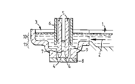
Referring to the drawings, like reference numerals are
used throughout to denote like parts. Thus connmon to all
~ four structures is a refractory lined forehearth 1
through which molten glass_flows in the direction of the
arrow 2 towards a feeder. At its end, the feeder is
constructed as a refractory lined or monolithic basin 3
having in its base 9 a glass-discharge outlet 7 closed in
-turn by a closure member ~ having in'it one, or more,
apertures 4 through which glass array streazc~, or gobs of
glass may be pressed by means of a vertically
reciprocating pair of gob plungers 5 actuated by means
not illustrated in the drawings For the sake of clarity,
the top structure, which is conventionally located above
the feed~r.and which may. for e~cample incorporate heating
means, has bean omitted.
Surrounding the plungers is a refractory hollow metering
cylinder 6 which is 5loraly rotated and which may be
raised and:low~red o lave a gap between its 7,ow~r ex~d
and the floor of basin 3 when it is desired to dispense
ahd'adjust the'fZow of-glass through the outlet
apertures.
The known structure of Figure 1 does not lead to
particularly homogeneous'ou~tput from the apertures.
however, when, in accordance with the px~sent invention,
the basin as divided ~.nto an upper portion la and a lower'
smaller cross-sectional area portion 11; it is
surprisingly found that a.mproved results ars obtained.
Preliminary experiments with structures in acGOrdance
w~.th the invention have shown that the molten glass tends
to flow gently and homogeneously through the forehearth
WO 9/20630 ~ ~ ~ ~~ ~ ~ 1PC'lf/G~92/00895
_ g _
channel into the top portion of the basin maintaining
good homogeneity and is then rapidly and symmetrically
moved down in the annular space between the cylinder S
and the outer walls of the lower portion of the basin as
molten glass is drawn through the apertures. With the
gob feeder arrangement shown, the glass has only a
relatively short dwell time in the lower space between
the basin wall and the rotating cylinder, so it stays
homogeneous while it is formed into gobs and ejected
through the apertures 4.
A particular advantage of the basin design in accordance
with the preseaxt invention is that it may be operated in
simple fashion to avoid the formation of large and
essentially stagnant volumes of molten g3.ass. Prhese tend
to form in the upper regibns of known pouring basins, and
lumps of relatively more viscous glass can tend to break
off from the stagnant regions and become entrained in,
but not homogeneously mixed with, the glass as it flows
out of the~basin, thus leading to inhomogeneities in the
products made from the glass. We haua found that such
problems may be aninimised or alleviated entirely when
operating with a basin in accordance with the present
invention by regularly varying the rotational speed of
the refractory cylinder and hence moving the location of
the stagnant regi~n. The effect is enhanced if the upper
portion of the refractory cylinder which is located in
the upper section of the basin is of larger diameter than
the lower,porti~n t~a~re~f located in the lower section of
the basin.
Further advantages of the basin structure of the present y
irwention consist in .the availability of a relatively
larger upper surface area for temperature control of the
WO 92/20630 ~ 1 ~ ~ ~ ~ U ~cric~9~ioos~s
- to -
body of glass in the basin compared to the volume of the.
basin itself as contrasted with known basin designs. The
narrower lower region, however, lends itself to fine
temperature control, for example achieved by the
~ provision of extra insulation or extra heating, thus
improving the overall controllability of the glass
dispensing process at the output easel of the forehearth.
The basic design according to the present invention
provides the advantages outlined above when used in
connection with fixed cylinderiseparate stirrer
arrangements as well as with the rotating cylinder
arrangement illustrated.
The detailed geometry and geometrical ratios gay be
varied widely writhout departing from the scope of the
present invention. In contrast to the prior art basins,
which were not d.ivi.ded into upper and lower regions,
clearly distinct from one another, the present invention,
2O by providing that division, provides a considerably
improved homogeneity of glass output together with
enhanced control possibilities:
It is within the purview of the present in~rention for the
2~ basin to be made and sold as a sepax'ate product. This
permits it to be retro-fitted on to the forehearth of an
existing furnace. ~'he manner in wrhich the basin could be
connected to a forehearth does not form part of the
subject-matter of this invonta:on, and so wi:l1 not be
30 described~herein in'any greater detail.