Note: Descriptions are shown in the official language in which they were submitted.
WO92/16082 PCT/US92/01873
- 1 - 2 1 03543
DRTVFR CIRCUIT FOR A PT.URATITY OF r.~s DISCH~RGF. LAMPS
R~ckground of the Invent;on
This invention relates to driver circuits for a
plurality of gas discharge lamps.
In a typical prior art driver circuit for a
plurality of gas discharge lamps the lamps are driven in
series directly by a voltage developed across the
secondary winding of a transformer. The voltage
developed across the transformer secondary winding must
be high enough to cause all of the lamps to strike when
the circuit is powered on. However, setting the voltage
developed across the transformer secondary winding at an
otherwise desirable high level may contravene safety
requirements and may increase operating stress on the
circuit's switching components to an unacceptable degree.
It is known to connect to the lamps capacitors which
act as starting aids, in order to increase the pre-strike
voltage applied to the lamps. However, for driving three
or more series-connected lamps, such capacitor starting
aid configurations may still have to generate secondary
winding voltages which are close to or exceed safety
limits.
Sl~mm~ry of the Invention
In accordance with a first aspect of the invention
there is provided a circuit for driving a plurality of
gas discharge lamps, the circuit comprising:
input terminals for connection to a source of
voltage supply;
WO92/16082 PCT/US92/01873
2 2t o3543
first and second output terminals for connection
across a plurality of gas discharge lamps in series;
oscillator means coupled to the input terminals for
producing a high-frequency voltage;
a transformer having a primary wind ing coupled to
the oscillator means to receive the high-frequency
voltage and having a secondary winding coupled to the
output terminals,
the improvement comprising:
a third output terminal for connection to the lamps
intermediate the first and second output terminals,
the secondary winding of the transformer having
thereon first and second points and a third point
intermediate the first and second points,
the first and third points on the secondary winding
of the transformer being coupled respectively to the
first and second output terminals, and
first capacitance means coupling the second point on
the secondary winding of the transformer to the third
output terminal.
The voltage produced by the portion of the secondary
winding between the first and third points thus drives
the lamps in series, while the pre-strike voltage
produced across the whole of the secondary winding
between the first and second points is applied between
the first and third output terminals to aid striking of
the lamp or lamps connected therebetween. After
striking, current to the third output terminal is limited
by the first capacitance means. In this way, the voltage
which needs to be produced across the whole of the
secondary winding to ensure striking of all of the lamps
may be reduced.
In accordance with a second aspect of the present
invention there is provided a circuit for driving a
plurality of gas discharge lamps, the circuit comprising:
WO92/16082 PCT/US92/01873
~ _ 3 _ 2 1 0 3 5 4 3
input terminals for connection to a source of
voltage supply;
first and second output terminals for connection
across a plurality of gas discharge lamps in seriesi
oscillator means coupled to the input terminals for
producing a high-frequency voltage;
a transformer having a primary winding coupled to
the oscillator means to receive the high-frequency
voltage and having a secondary winding coupled to the
output terminals,
the improvement comprising:
a third output terminal for connection to the lamps
intermediate the first and second output terminals,
the secondary winding of the transformer having
thereon first and second points coupled respectively to
the first and second output terminals, and
first capacitance means coupling the first point on
the secondary winding of the transformer to the third
output terminal, so as to increase pre-strike voltage
between the second and third output terminals.
The voltage produced by the secondary winding
between the first and second points thus drives the lamps
in series. Before striking, the pre-strike voltage
produced across the secondary winding between the first
and second points is applied between the second and third
output terminals to aid striking of the lamp or lamps
connected therebetween. After striking, current to the
third output terminal is limited by the first capacitance
means. In this way, the voltage which needs to be
produced across the secondary winding to ensure striking
of all of the lamps may be reduced.
In accordance with a third aspect of the invention
there is provided a circuit for driving a plurality of
gas discharge lamps, the circuit comprising:
WO92/16082 PCT/US92/01873
~ 4 ~ 21Q3543
input terminals for connection to a source of
voltage supply;
first and second output terminals for connection
across a plurality of gas discharge lamps in series;
oscillator means coupled to the input terminals for
producing a high-frequency voltage;
a transformer having a primary winding coupled to
the oscillator means to receive the high-frequency
voltage and having a secondary winding coupled to the
output terminals,
the improvement comprising:
a third output terminal for connection to the lamps
intermediate the first and second output terminals,
the secondary winding of the transformer having
thereon first and second points coupled respectively to
the first and second output terminals and having a third
point thereon adjacent the first point and intermediate
the first and second points, and
first capacitance means coupling the third point on
the secondary winding of the transformer to the third
output terminal, so as to increase pre-strike voltage
between the second and third output terminals.
The voltage produced by the secondary winding
between the first and second points thus drives the lamps
in series. Before striking, the pre-strike voltage
produced across the secondary winding between the second
and third points is applied between the second and third
output terminals to aid striking of the lamp or lamps
connected therebetween. After striking, current to the
third output terminal is limited by the first capacitance
means. In this way, the voltage which needs to be
produced across the secondary winding to ensure striking
of all of the lamps may be reduced.
WO92/16082 PCT/USg2/01873
- 5 ~ 2103543
Rr;ef Descr;ption of the Dr~wings
Six fluorescent lamp driver circuits in accordance
with the present invention will now be described, by way
of example only, with reference to the accompanying
drawings, in which:
FIG. 1 shows a schematic circuit diagram of a
first driver circuit for driving three
fluorescent lampsi
FIG. 2 shows a schematic circuit diagram of a
second driver circuit for driving three
fluorescent lamps
FIG. 3 shows a schematic circuit diagram of a
third driver circuit for driving four
fluorescent lampsi
FIG. 4 shows a schematic circuit diagram of a
fourth driver circuit for driving four
fluorescent lampsi
FIG. 5 shows a schematic circuit diagram of a
fifth driver circuit for driving three
fluorescent lampsi and
FIG. 6 shows a schematic circuit diagram of a
sixth driver circuit for driving three
fluorescent lamps.
Descr;Dtlo'n of the Preferred F~mho~iment
Referring now to Figure 1, a first driver circuit
100 for driving three fluorescent lamps 102, 104 and 106
includes output terminals 108, 110, 112 and 114 between
WO92/16082 PCT/US92/01873
- 6 - 2103543
which the lamps are connected in series. The circuit 100
has input terminals 115, 116 for connection to a 120VAC,
60Hz utility mains. The input terminals are coupled
through a conventional power supply section 117 and a
conventional inverter section 118 to a series-resonant
tank circuit formed by an inductor 120 (having a value of
approximately 1.6mH) and a capacitor 122 (having a value
of approximately 4.7~F) connected in series.
A transformer 124 has a primary winding 126,
connected in parallel with the capacitor 122, and a
secondary winding 128. The primary and secondary
windings 126 and 128 are wound on a core 130 in a total
turns ratio of approximately 1:1.9, the primary winding
126 having approximately 120 turns and the secondary
winding 128 having approximately 230 turns in total. The
ends 129A, 129B of the secondary winding 128 are
connected via respective capacitors 132, 134 (each having
a value of approximately 200pF) to the two innermost
output terminals 112 and 110 respectively. The secondary
winding 128 is tapped at two intermediate points 136 and
138 to form a central secondary winding portion 140
having approximately 170 turns and two extremity winding
portions 142 and 144 each having approximately 30 turns.
The intermediate tapping points 136 and 138 are connected
respectively to the two outermost output terminals 108
and 114. A starting aid capacitor 146 (having a value of
approximately lOOpF) is connected between the two
innermost output terminals 110 and 112.
For simplicity of illustration, lamp filament heater
windings, which would typically be provided from the same
transformer 124 in conventional manner, are not shown.
In use of the driver circuit 100, alternating mains
voltage (e.g. 120VAC, 60Hz) is applied across the input
terminals 115, 116. The inductor 120 and the capacitor
WO92/16082 PCT/US92/01873
- 7 - 2103543
122 form an LC series-resonant circuit which, energized
by the applied mains voltage via the power supply 117 and
the inverter 118, resonates at a nominal loaded frequency
of approximately 40KHz. The high-frequency voltage
produced by the resonant circuit appears across the
primary winding 126 of the transformer 124. The high-
frequency voltage produced by the resonant circuit is
conveyed by the transformer 124 and produces a high-
frequency voltage in the secondary winding 128. The
high-frequency voltage produced in the secondary winding
128 is applied to the output terminals 108, 110, 112,
114, and so across the series-connected lamps 102, 104,
106, in the following way.
Compared with a conventional lamp connection
arrangement in which the three lamps would be simply
connected in series across the whole of the secondary
winding and would each experience the same pre-struck
voltage equal to one third of the total voltage produced
across the secondary winding, in the circuit 100 the
lamps experience greatly increased pre-struck voltages,
as follows. The voltage produced across the combination
of the central portion 140 and the upper extremity
portion 142 of the secondary winding 128 is applied, via
the capacitor 132, across the single lamp 106.
Similarly, a voltage of the same value, that produced
across the combination of the central portion 140 and the
lower extremity portion 144 of the secondary winding 128,
is applied, via the capacitor 134, solely across the
single lamp 102. The voltage produced across the whole
of the secondary winding 128 (i.e. the central portion
140 and both of the extremity portions 142 and 144) is
applied across a capacitive divider formed by the
capacitors 132, 134 and 146 which are connected in
series. Since the impedance of the capacitor 146 is
approximately half of the total impedance of the
capacitive divider, the voltage which is produced across
WO92/16082 PCT/US92/01873
- 8 - 2103543
the capacitor 146 and which is applied across the lamp
104, is approximately half of the voltage produced across
the whole of the secondary winding.
Hence compared with a conventional lamp connection
arrangement in which the three lamps would be simply
connected in series across the whole of the secondary
winding and would each experience the same pre-struck
voltage equal to one third of the total voltage produced
across the secondary winding, in the circuit 100 the
lamps 102 and 106 experience a pre-struck voltage which
is approximately 2.6 times as high and the lamp 104
experiences a voltage which is 1.5 times as high.
Thus, the lamps 102 and 106, having significantly
higher voltages applied to them than the lamp 104, strike
first. Once the lamps 102 and 106 have struck, the
impedances provided by the capacitors 132 and 134 allow
only an insignificantly small amount of current to flow
in the extremity windings 142 and 144, and so cause the
three lamps 102, 104 and 106 to be driven in series
substantially entirely from the central portion 140 of
the secondary winding 128. Thus, since the lamps 102 and
106 are struck and present a low voltage drop
thereacross, substantially the whole of the voltage
produced in the central portion 140 of the secondary
winding 128 is applied across the remaining unstruck lamp
104 and causes the lamp to strike. Once the lamp 104 has
struck its impedance is far less than that of the
capacitor 146, and so the capacitor carries only an
insignificantly small amount of current.
Thus, with all of the lamps 102, 104 and 106 struck,
the impedances of the capacitors 132, 134 and 146 are far
greater than those of the lamps, and so the capacitors
have no significant effect on the steady-state function
of the circuit, allowing the three lamps 102, 104 and 106
WO92/16082 PCT/US92/01873
_ - 9 2103543
to be driven in series substantially entirely from the
central portion 140 of the secondary winding 128.
Thus, it will be appreciated that the circuit 100
allows the lamps to be driven with pre-struck voltages
greatly exceeding those in a conventional arrangement
without producing a significantly greater total secondary
winding voltage.
Referring now to FIG. 2, a second driver circuit 200
for driving three fluorescent lamps 202, 204 and 206
includes output terminals 208, 210, 212 and 214 between
which the lamps are connected in series. The circuit 200
has input terminals 215, 216 for connection to a 120VAC,
60Hz utility mains. The input terminals are coupled
through a conventional power supply section 217 and a
conventional inverter section 218 to a series-resonant
tank circuit formed by an inductor 220 (having a value of
approximately 1.6mH) and a capacitor 222 ~having a value
of approximately 4.7~F) connected in series.
A transformer 224 has a primary winding 226,
connected in parallel with the capacitor 222, and a
secondary winding 228. The primary and secondary
windings 226 and 228 are wound on a core 230 in a total
turns ratio of approximately 1:1.9, the primary winding
226 having approximately 220 turns and the secondary
winding 228 having approximately 230 turns in total. The
ends 229A, 229B of the secondary winding 228 are
connected via respective capacitors 232, 234 (each having
a value of approximately 200pF) to the two innermost
output terminals 210 and 212 respectively. The secondary
winding 228 is tapped at two intermediate points 236 and
238 to form a central secondary winding portion 240
having approximately 170 turns and two extremity winding
portions 242 and 244 each having approximately 30 turns.
The intermediate tapping points 236 and 238 are connected
WO92/16082 PCT/US92/01873
- lo- ~o3543
respectively to the two outermost output terminals 208
and 214.
For simplicity of illustration, lamp filament heater
windings, which would typically be provided from the same
transformer 224 in conventional manner, are not shown.
In use of the driver circuit 200, alternating mains
voltage (e.g. 120VAC, 60HZ) is applied across the input
terminals 215, 216. The inductor 220 and the capacitor
222 form an LC series-resonant circuit which, energized
by the applied mains voltage via the power supply 217 and
the inverter 218, resonates at a nominal loaded frequency
of approximately 40KHZ . The high-frequency voltage
produced by the resonant circuit appears across the
primary winding 226 of the transformer 224. The high-
frequency voltage produced by the resonant circuit is
conveyed by the transformer 224 and produces a high-
frequency voltage in the secondary winding 228. The
20 high-frequency voltage produced in the secondary winding
228 is applied to the output terminals 208, 210, 212,
214, and so across the series-connected lamps 202, 204,
206, in the following way.
Compared with a conventional lamp connection
arrangement in which the three lamps would be simply
connected in series across the whole of the secondary
winding and would each experience the same pre-struck
voltage equal to one third of the total voltage produced
across the secondary winding, in the circuit 200 an
increased pre-struck voltage is produced, as follows.
The voltage produced across the whole of the secondary
winding 228 (i.e. the central portion 240 and both of the
extremity portions 242 and 244) is applied across the
35 single lamp 204. The voltage produced across the upper
extremity winding 242 is applied across the single lamp
W092/l6082 PCT/US92/01873
`~ - 11 - 2 1 03543
202, and the voltage produced across the lower extremity
winding 244 is applied across the single lamp 206.
Hence compared with a conventional lamp connection
arrangement in which the three lamps would be simply
connected in series across the whole of the secondary
winding and would each experience the same pre-struck
voltage equal to one third of the total voltage produced
across the secondary winding, in the circuit 200 the
lamps 202 and 206 initially experience a lower voltage
while the lamp 204 experiences a voltage which is 3 times
as high. This causes the lamp 204 to strike rapidly and
first. Once the lamp 204 has struck the impedances
provided by the capacitors 232 and 234 allow only an
insignificantly small amount of current to flow in the
extremity windings 242 and 244, and so cause the three
lamps 202, 204 and 206 to be driven in series
substantially entirely from the central portion 240 of
the secondary winding 228. In this condition, with the
lamp 204 struck and presenting very little voltage drop
thereacross compared with the unstruck lamps 202 and 206,
the voltage produced by the central portion 240 of the
secondary winding 228 is applied across the three series-
connected lamps and results in each of the lamps 202 and
206 experiencing approximately half of this voltage.
This causes the lamps 202 and 206 to strike rapidly, and
all three lamps are then driven in series from the
central portion 240 of the secondary winding 228.
Thus, it will be appreciated that the circuit 200
allows the lamps to be struck with pre-struck voltages
greater than in a conventional arrangement, without
producing a significantly greater total secondary winding
voltage.
Referring now to Figure 3, a third driver circuit
300 for driving four fluorescent lamps 302, 304, 306 and
WO92/16082 PCT/US92/01873
- 12 ~ 2~03543
308 includes output terminals 310, 312, 314, 316 and 318
between which the lamps are connected in series. The
circuit 300 has input terminals 319, 320 for connection
to a 120VAC, 60Hz utility mains. The input terminals are
coupled through a conventional power supply section 321
and a conventional inverter section 322 to a series-
resonant tank circuit formed by an inductor 324 (having a
value of approximately 1.6mH) and a capacitor 326 (having
a value of approximately 4.7~F) connected in series.
A transformer 328 has a primary winding 330,
connected in parallel with the capacitor 326, and a
secondary winding 332. The primary and secondary
windings 330 and 332 are wound on a core 334 in a total
turns ratio of approximately 1:1.9, the primary winding
330 having approximately 120 turns and the secondary
winding 332 having approximately 230 turns in total. The
ends 333A, 333B of the secondary winding 332 are
connected via respective capacitors 336, 338 (each having
a value of approximately 200pF) to the inner output
terminals 316 and 312 respectively. The secondary
winding 332 is tapped at two intermediate points 340 and
342 to form a central secondary winding portion 344
having approximately 170 turns and two extremity winding
portions 346 and 348 each having approximately 30 turns.
The intermediate tapping points 340 and 342 are connected
respectively to the two outermost output terminals 310
and 318. A starting aid capacitor 350 (having a value of
approximately lOOpF) is connected between the innermost
output terminal 314 and the inner output terminal 316.
For simplicity of illustration, lamp filament heater
windings, which would typically be provided from the same
transformer 328 in conventional manner, are not shown.
In use of the driver circuit 300, alternating mains
voltage (e.g. 120VAC, 60Hz) is applied across the input
WO92/16082 PCT/US92/01873
- 13 - 2103543
terminals 319, 320. The inductor 324 and the capacitor
326 form an LC series-resonant circuit which, energized
by the applied mains voltage via the power supply 321 and
the inverter 322, resonates at a nomlnal loaded frequency
of approximately 40KHz. The high-frequency voltage
produced by the resonant circuit appears across the
primary winding 330 of the transformer 328. The high-
frequency voltage produced by the resonant circuit is
conveyed by the transformer 328 and produces a high-
frequency voltage in the secondary winding 332. Thehigh-frequency voltage produced in the secondary winding
332 is applied to the output terminals 310, 312, 314,
316, 318 and so across the series-connected lamps 302,
304, 306, 308 in the following way.
Compared with a conventional lamp connection
arrangement in which the four lamps would be simply
connected in series across the whole of the secondary
winding and would each experience the same pre-struck
voltage equal to one quarter of the total voltage
produced across the secondary winding, in the circuit 300
the lamps experience greatly increased pre-struck
voltages, as follows. The voltage produced across the
combination of the central portion 344 and the upper
extremity portion 346 of the secondary winding 332 is
applied, via the capacitor 336, across the single lamp
308. Similarly, a voltage of the same value, that
produced across the combination of the central portion
344 and the lower extremity portion 348 of the secondary
winding 332, is applied, via the capacitor 338, solely
across the single lamp 302. The voltage produced across
the whole of the secondary winding 332 ~i.e. the central
portion 344 and both of the extremity portions 346 and
348) is applied via the capacitors 336, 338 and 350 to
appear substantially across the inner lamp 304. Since
the other inner lamp 306 has the capacitor 350 connected
in parallel with it, the voltage produced across the lamp
WO92/16082 PCT/US92/01873
- 14 - 21 03543
306 is significantly smaller than that produced across
the lamp 304.
Hence compared with a conventional lamp connection
arrangement in which the four lamps would be simply
connected in series across the whole of the secondary
winding and would each experience the same pre-struck
voltage equal to one quarter of the total voltage
produced across the secondary winding, in the circuit 300
the lamps 302 and 308 experience a pre-struck voltage
which is approximately 3.5 times as high and the lamps
304 experiences a voltage which is approximately 4 times
as high. Thus, the inner lamp 304 is caused to strike
rapidly and first.
Once the lamp 304 has struck, the voltage across the
lamp drops substantially and the circuit becomes
equivalent to the circuit 100 of FIG. 1 which has already
been discussed. Thus, once the lamp 304 has struck, the
outer lamps 302 and 308 next strike rapidly. Once the
lamps 304, 302 and 308 have struck, the impedances
provided by the capacitors 336 and 338 allow only an
insignificantly small amount of current to flow in the
extremity windings 346 and 348, and so cause all four
lamps 302, 304, 306 and 308 to be driven in series
substantially entirely from the central portion 344 of
the secondary winding 332. Thus, since the lamps 302,
304 and 308 are struck and present a low voltage drop
thereacross, substantially the whole of the voltage
produced in the central portion 344 of the secondary
winding 332 is applied across the remaining unstruck lamp
306 and causes the lamp to strike. Once the lamp 306 has
struck its impedance is far less than that of the
capacitor 350, and so the capacitor carries only an
insignificantly small amount of current.
WO92/16082 PCT/US92/01873
- - 15 - 21 03543
Thus, with all of the lamps 302, 304, 306 and 308
struck, the impedances of the capacitors 336, 338 and 350
are far greater than those of the lamps, and so the
capacitors have no significant effect on the steady-state
function of the circuit, allowing the four lamps 302,
304, 306 and 308 to be driven in series substantially
entirely from the central portion 344 of the secondary
winding 332.
Thus, it will be appreciated that the circuit 300
allows the lamps to be driven with pre-struck voltages of
approximately 4 and 3.5 times as great as in a
conventional arrangement without producing a
significantly greater total secondary winding voltage.
Referring now to Figure 4, a fourth driver circuit
400 for driving four fluorescent lamps 402, 404, 406 and
308 includes output terminals 410, 412, 414, 416 and 418
between which the lamps are connected in series. The
circuit 400 has input terminals 419, 420 for connection
to a 120VAC, 60Hz utility mains. The input terminals are
coupled through a conventional power supply section 421
and a conventional inverter section 422 to a series-
resonant tank circuit formed by an inductor 424 (having a
value of approximately 1.6mH) and a capacitor 426 (having
a value of approximately 4.7~F) connected in series.
A transformer 428 has a primary winding 430,
connected in parallel with the capacitor 426, and a
secondary winding 432. The primary and secondary
windings 430 and 432 are wound on a core 434 in a total
turns ratio of approximately 1:1.9, the primary winding
430 having approximately 120 turns and the secondary
winding 432 having approximately 230 turns in total. The
ends 433A, 433B of the secondary winding 432 are
connected via respective capacitors 436, 438 (each having
a value of approximately 200pF) to the inner output
WO92/16082 PCT/US92/01873
- 16 - ~ o3543
terminals 412 and 416 respectively. The secondary
winding 432 is tapped at two intermediate points 440 and
442 to form a central secondary winding portion 444
having approximately 170 turns and two extremity winding
portions 446 and 448 each having approximately 30 turns.
The intermediate tapping points 440 and 442 are connected
respectively to the two outermost output terminals 410
and 418. A starting aid capacitor 450 (having a value of
approximately lOOpF) is connected between the innermost
output terminal 414 and the inner output terminal 416.
For simplicity of illustration, lamp filament heater
windings, which would typically be provided from the same
transformer 428 in conventional manner, are not shown.
In use of the driver circuit 400, alternating mains
voltage (e.g. 120VAC, 60Hz) is applied across the input
terminals 419, 420. The inductor 424 and the capacitor
426 form an LC series-resonant circuit which, energized
by the applied mains voltage via the power supply 421 and
the inverter 422, resonates at a nominal loaded frequency
of approximately 40KHz. The high-frequency voltage
produced by the resonant circuit appears across the
primary winding 430 of the transformer 428. The high-
frequency voltage produced by the resonant circuit isconveyed by the transformer 428 and produces a high-
frequency voltage in the secondary winding 432. The
high-frequency voltage produced in the secondary winding
432 is applied to the output terminals 410, 412, 414,
416, 418 and so across the series-connected lamps 402,
404, 406, 408 in the following way.
Compared with a conventional lamp connection
arrangement in which the four lamps would be simply
connected in series across the whole of the secondary
winding and would each experience the same pre-struck
voltage equal to one quarter of the total voltage
WO92/16082 PCT/US92/01873
~ - 17 - 21 03543
produced across the secondary winding, in the circuit 400
an increased pre-struck voltage is produced, as follows.
The voltage produced across the upper extremity winding
446 is applied across the single lamp 402, and the
voltage produced across the lower extremity winding 448
is applied across the single lamp 408. The voltage
produced across the whole of the secondary winding 432
(i.e. the central portion 444 and both of the extremity
portions 446 and 448) is applied, via the capacitors 436
and 438, across the two innermost lamps 404 and 406
connected in series; since the capacitor 450 is connected
in parallel with the lamp 406, very little of this
voltage appears across the lamp 406 and substantially the
whole of this voltage appears across the lamp 404.
Hence compared with a conventional lamp connection
arrangement in which the four lamps would be simply
connected in series across the whole of the secondary
winding and would each experience the same pre-struck
voltage equal to one quarter of the total voltage
produced across the secondary winding, in the circuit 400
the lamps 402, 406 and 408 initially experience lower
voltages while the lamp 404 experiences a voltage which
is approximately 4 times as high. This causes the lamp
404 to strike rapidly and first. Once the lamp 404 has
struck, the lamp 406 strikes next; once the lamp 406 has
struck its impedance is far less than that of the
capacitor 450, and so the capacitor carries only an
insignificantly small amount of current. Once the lamps
404 and 406 have struck, the impedances provided by the
capacitors 436 and 438 allow only an insignificantly
small amount of current to flow in the extremity windings
446 and 448, and so cause the four lamps 402, 404, 406
and 408 to be driven in series substantially entirely
from the central portion 444 of the secondary winding
432. In this condition, with the lamps 404 and 406
struck and presenting very little voltage drop
WO92/16082 PCT/US92/01873
21 03543
- 18 -
thereacross compared with the unstruck lamps 402 and 408,
the voltage produced by the central portion 444 of the
secondary winding 432 is applied across the four series-
connected lamps and results in each of the lamps 404 and
406 experiencing approximately half of this voltage.
This causes the lamps 404 and 406 to strike rapidly, and
all four lamps are then driven in series from the central
portion 444 of the secondary winding 432.
Thus, it will be appreciated that the circuit 400
allows the lamps to be struck sequentially with pre-
struck voltages twice as great as in a conventional
arrangement, without increasing voltage levels at other
points within the circuit or without producing a
significantly greater total secondary winding voltage.
It will be understood that by decreasing the
impedance of the capacitor 450 with respect to the
impedances of the capacitors 436 and 438, the lamp 406
could be made to strike before the outer.lamps 402 and
408, if desired.
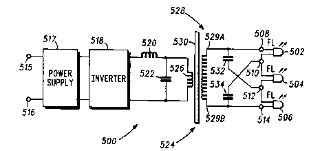
Referring now to Figure 5, a fifth driver circuit
500 for driving three fluorescent lamps 502, 504 and 506
includes output terminals 508, 510, 512 and 514 between
which the lamps are connected in series. The circuit 500
has input terminals 515, 516 for connection to a 120VAC,
60Hz utility mains. The input terminals are coupled
through a conventional power supply section 517 and a
conventional inverter section 518 to a series-resonant
tank circuit formed by an inductor 520 (having a value of
approximately 1.6mH) and a capacitor 522 (having a value
of approximately 4.7~F) connected in series.
A transformer 524 has a primary winding 526,
connected in parallel with the capacitor 522, and a
secondary winding 528. The primary and secondary
WO92/16082 PCT/US92/01873
- 19;- 2103543
windings 526 and 528 are wound on a core 530 in a total
turns ratio of approximately 1:1.9, the primary winding
526 having approximately 120 turns and the secondary
winding 528 having approximately 230 turns in total. The
ends 529A, 529B of the secondary winding 528 are
connected respectively to the two outermost output
terminals 508 and 514. The ends 529A, 529B of the
secondary winding 528 are also connected via respective
capacitors 532, 534 (each having a value of approximately
200pF) to the two innermost output terminals 512 and 510
respectively.
For simplicity of illustration, lamp filament heater
windings, which would typically be provided from the same
transformer 524 in conventional manner, are not shown.
It will be understood that the driver circuit 500 of
FIG. 5 represents a simplified version of the driver
circuit 100 described above, in which the lengths of the
extremity portions 142 and 144 are reduced to zero, the
outermost output terminals 108 and 114 are connected
directly to the ends 129A and 129B of the secondary
winding 128, and the starting aid capacitor 146 is
removed. It will be appreciated that the driver circuit
500 of FIG. 5 operates similarly to the driver circuit
100 as follows.
In use of the driver circuit 500, alternating mains
voltage (e.g. 120VAC, 60Hz) is applied across the input
terminals 515, 516. The inductor 520 and the capacitor
522 form an LC series-resonant circuit which, energized
by the applied mains voltage via the power supply 517 and
the inverter 518, resonates at a nominal loaded frequency
of approximately 40KHz. The high-frequency voltage
produced by the resonant circuit appears across the
primary winding 526 of the transformer 524. The high-
frequency voltage produced by the resonant circuit is
WO92/16082 PCT/US92/01873
.
- 20 - 2 1 0 3 5 4 3 --
conveyed by the transformer 524 and produces a high-
frequency voltage in the secondary winding 528. The
high-frequency voltage produced in the secondary winding
528 is applied to the output terminals 508, 510, 512,
514, and so across the series-connected lamps 502, 504,
506, in the following way.
Compared with a conventional lamp connection
arrangement in which the three lamps would be simply
connected in series between the ends of the secondary
winding and would each experience the same pre-struck
voltage equal to one third of the total voltage produced
across the secondary winding, in the circuit 500 the
lamps experience greatly increased pre-struck voltages,
as follows. The voltage produced across the secondary
winding 528 between its ends 529A and 529B is applied,
via the capacitor 532, across the single lamp 506.
Similarly, the same voltage developed across the
secondary winding 528 between its ends 529A and 529B is
applied, via the capacitor 534, across the single lamp
502. Also, the same voltage developed across the
secondary winding 528 between its ends 529A and 529B is
applied, via the capacitor 532 and 534, across the single
lamp 504.
Hence compared with a conventional lamp connection
arrangement in which the three lamps would be simply
connected in series across the whole of the secondary
winding and would each experience the same pre-struck
voltage equal to one third of the total voltage produced
across the secondary winding, in the circuit 100 the
lamps 102, 104 and 106 each experience a pre-struck
voltage which is approximately 3 times as high.
In fact it will be understood that the voltages
produced at the two innermost output terminals 510 and
512 are of slightly less magnitude than the voltages
WO92/16082 PCT/US92/01873
~ - 21 - 2103543
produced at the ends 529B and 529A respectively of the
secondary winding 528 due to the presence of the
capacitors 132 and 134, causing the voltage produced
across the lamp 504 to be slightly less than the voltages
produced across the lamps 502 and 504.
Thus, the lamps 502 and 506, having higher voltages
applied to them than the lamp 504, strike first. Once
the lamps 502 and 506 have struck, the impedances
provided by the capacitors 532 and 534 allow only an
insignificantly small amount of current to flow between
the ends 529A, 529B of the secondary winding 528 and the
two innermost output terminals 512 and 510 respectively,
and so cause the three lamps 502, 504 and 506 to be
driven in series from the voltage produced between the
ends 529A and 529B of the secondary winding 528. Thus,
since the lamps 502 and 506 are struck and present a low
voltage drop thereacross, substantially the whole of the
voltage produced in the secondary winding 528 is applied
across the remaining unstruck lamp 504 and causes the
lamp to strike.
Thus, it will be appreciated that the circuit 500
allows the lamps to be driven with pre-struck voltages
greatly exceeding those in a conventional arrangement
without producing a significantly greater total secondary
winding voltage.
It will be understood that it is not necessary for
the capacitors 532 and 534 to be connected to precisely
the ends 529A and 529B respectively of the secondary
winding 528 in order to increase the pre-strike voltage
across the fluorescent lamps 502, 504 and 506. For
example, it will be appreciated that the capacitors 532
and 534 may be connected to points on the secondary
winding 528 which are adjacent to the ends 529A and 529B,
WO92/16082 PCT/US92/01873
- 22 - 2 1 0 3 5 4 3
producing a lower (but still beneficial) increase in pre-
strike voltage across the lamps.
Such an arrangement is employed in the driver
circuit shown in FIG. 6, which is identical to the drlver
circuit of FIG. 5 except in only one respect: instead of
capacitors being connected directly between the lnnermost
output terminals and the ends of the secondary winding as
in FIG. 5, the capacitors 632 and 634 are instead
connected directly between innermost output terminals 612
and 610 and tapping points 629C and 629D which are
adjacent to ends 629A and 629B respectively of secondary
winding 628. In all other respects the driver circuit of
FIG. 6 is identical with the circuit of FIG. 5 and
operates in a similar manner as described above, and so
will not be described in further detail. It will be
understood that the greater the distances along the
secondary winding between the point 629C and the end 629A
and between the point 629D and the end 629B, the less
will be the increased pre-strike voltage effect compared
with that produced in the circuit of FIG. 5 discussed
above.
It will be understood that (similarly to viewing the
driver circuit 500 of FIG. 5 as a simplified version of
the driver circuit 100 of FIG. 1 in which the secondary
winding extremity portions 142 and 144 have zero lengths,
as discussed above) the driver circuit 600 of FIG. 6 may
be considered an analogous version of the driver circuit
100, in which the extremity portions 142 and 144 have
negative lengths (i.e., they extend into, rather than out
from, the central core portion 140).
Thus, comparing the driver circuit of FIG. 6 with
that of FIG. 5, it will be understood that by connecting
capacitors between intermediate points along the series
connected lamps and points on the secondary winding which
WO92/16082 PCT/USg2/01873
- - - 23 - 2 1 03543
are closer together than the points on the secondary
winding between which the lamps are connected in series,
the pre-strike voltage experienced by the lamps is
decreased (although the coupling of the capacitors in
both of these circuits still produces an increase in pre-
strike voltage). It will also be understood, comparing
the driver circuit of FIG. 1 with that of FIG. 5, that by
connecting capacitors between intermediate points along
the series connected lamps and points on the secondary
winding which are farther apart than the points on the
secondary winding between which the lamps are connected
in series, the pre-strike voltage experienced by the
lamps is increased (although the coupling of the
capacitors in both of these circuits still produces an
increase in pre-strike voltage).
Thus, it will be appreciated that the points on the
secondary winding at which capacitors are connected to
enhance the pre-strike voltage may be either: (i) at the
points on the secondary winding between which the lamps
are connected in series (as in FIG. 5), or (ii) adjacent
to the points on the secondary winding between which the
lamps are connected in series (as in FIGS. 1-4 and
FIG. 6), and that in the second case the points on the
secondary winding at which the capacitors are connected
may be either between (as in FIG. 6) or outside of (as in
FIGS. 1-4 ) the points on the secondary winding between
which the lamps are connected in series to produce an
enhanced pre-strike voltage effect.
It will be appreciated that although in FIG. 1,
FIG. 2, FIG. 5 and FIG. 6 there have been described
circuits for driving three lamps, and in FIG. 3 and
FIG. 4 there have been described circuits for driving
four lamps, the invention is not restricted to the
driving of three or four lamps. It will be understood
WO92/16082 PCT/US92/01873
- 24 - ~03543
that the invention is also applicable to circuits for
driving two lamps or for driving five or more lamps.
It will be appreciated that various other
modifications or alternatives to the above described
embodiments will be apparent to a person skilled in the
art without departing from the inventive concept of
driving a plurality of gas discharge lamps in series from
a transformer secondary winding and providing a
capacitance which couples an intermediate junction of the
series-connected lamps to an end of the secondary winding
or to a point adjacent thereto so as to increase the pre-
struck voltage applied to one or more of the lamps.