Language selection

Search

Patent 2103771 Summary

Third-party information liability

Some of the information on this Web page has been provided by external sources. The Government of Canada is not responsible for the accuracy, reliability or currency of the information supplied by external sources. Users wishing to rely upon this information should consult directly with the source of the information. Content provided by external sources is not subject to official languages, privacy and accessibility requirements.

Claims and Abstract availability

Any discrepancies in the text and image of the Claims and Abstract are due to differing posting times. Text of the Claims and Abstract are posted:

  • At the time the application is open to public inspection;
  • At the time of issue of the patent (grant).
(12) Patent: (11) CA 2103771
(54) English Title: ROCKER ARM OF THE CAM-FOLLOWER TYPE FOR OPERATING TWO VALVES
(54) French Title: CULBUTEUR DU TYPE GALET SUIVEUR POUR LE FONCTIONNEMENT DE DEUX SOUPAPES
Status: Expired and beyond the Period of Reversal
Bibliographic Data
(51) International Patent Classification (IPC):
  • F01L 1/18 (2006.01)
(72) Inventors :
  • MILLS, JESSE V. (United States of America)
(73) Owners :
  • HENLEY MANUFACTURING HOLDING COMPANY, INC.
(71) Applicants :
  • HENLEY MANUFACTURING HOLDING COMPANY, INC. (United States of America)
(74) Agent: MACRAE & CO.
(74) Associate agent:
(45) Issued: 2004-10-26
(22) Filed Date: 1993-08-10
(41) Open to Public Inspection: 1994-05-06
Examination requested: 2000-08-02
Availability of licence: N/A
Dedicated to the Public: N/A
(25) Language of filing: English

Patent Cooperation Treaty (PCT): No

(30) Application Priority Data:
Application No. Country/Territory Date
07/972,427 (United States of America) 1992-11-05

Abstracts

English Abstract


A rocker arm of the cam-follower type simultaneously
operates two valves of a cylinder of an internal combustion
engine. The rocker arm includes an intermediate portion and
two end portions. The intermediate portion has upwardly
extending side walls and end walls forming a large generally
rectangular opening at the top edges thereof. The side walls
have aligned holes carrying an axle on which is rotatably
mounted a roller which contacts an overhead cam. One end
portion of the rocker arm has a downwardly-facing recess to
engage an upper end of a lifter post. The other end portion
of the rocker arm has a long, narrow web with downwardly-facing
pads. near the ends thereof and in predetermined, spaced
relationship. The pads engage upper ends of two valve stems
for simultaneously operating valves to which the stems are
connected.


Claims

Note: Claims are shown in the official language in which they were submitted.

THE EMBODIMENTS OF THE INVENTION IN WHICH AN EXCLUSIVE
PROPERTY OR PRIVILEGE IS CLAIMED ARE DEFINED AS FOLLOWS:
1. A rocker arm of the cam-follower type for
simultaneously operating two valves of a cylinder of an
internal combustion engine, said rocker arm comprising a
one-piece, cold-formed, metal body having an intermediate
portion, a first end portion, and a second end portion,
said intermediate portion having two upright side walls
and two end walls forming an upper opening, two flat webs
structurally integral with lower portions of said upright
side walls and extending outwardly therefrom, straight
stiffening flanges extending downwardly from outer edge
portions of said webs, said upright side walls having
aligned openings, an axle received in said aligned
openings, and a roller rotatably mounted on said axle and
exposed at said opening, said first end portion of said
body having a flat wall extending outwardly beyond one of
said end walls and being functionally integral with said
webs, stiffening flanges extending around edges of said
flat wall, a central portion of said flat wall having a
downwardly-facing recess for engaging an upper end of a
lifter post, said second end portion of said rocker arm
body having a long narrow web structurally integral with
the other of said end walls of said intermediate portion,
said second end portion having outwardly-extending
projections beyond the ends of said narrow web, and said
body having downwardly-facing convex surfaces forming pads
near said projections for engaging upper ends of valve
stems of the valves.
2. A rocker arm according to claim 1 wherein said
pads are located at end portions of said flat webs.
-8-

3. In combination, an internal combustion engine
having a cylinder with at least two valves, a lifter post
having an upwardly-extending rounded end located at one
side of said valves, means for supporting said lifter
post, a cam positioned near said valves and said lifter
post and located thereabove, a rocker arm of the
cam-follower type comprising a metal body having an
intermediate portion and two end portions, said
intermediate portion having upright side walls, said
intermediate portion having two flat webs structurally
integral with lower portions of said upright side walls
and extending outwardly therefrom, straight stiffening
flanges extending downwardly from outer edge portions of
said flat webs, an axle extending between said side walls,
and a roller rotatably mounted on said axle and positioned
in contact with said cam, one of said end portions of said
body having a downwardly-facing recess to engage an upper
end of said lifter post, the other end portion of said
body having downwardly-facing curved surfaces in
predetermined spaced relationship forming pads to engage
upper ends of valve stems of said valves, and said other
end portion having outwardly-extending projections near
said pads.
4. The combination according to claim 3 wherein said
intermediate portion has two end walls forming an upper
opening with said two upright side walls.
5. The combination according to claim 3 wherein said
one end portion has a flat wall in which said
downwardly-facing recess is formed.
-9-

6. The combination according to claim 5 wherein
stiffening flanges extend downwardly from edges of said
flat wall.
7. A rocker arm of the cam-follower type for
simultaneously operating two valves of a cylinder of an
internal combustion engine, said rocker arm comprising a
one-piece, metal body having an intermediate portion, a
first end portion, and a second end portion, said
intermediate portion having two aligned openings, said
intermediate portion having two upright side walls in
which said aligned openings are located, said intermediate
portion having two flat webs structurally integral with
lower portions of said upright side walls and extending
outwardly therefrom, and stiffening flanges extending
downwardly from outer edge portions of said flat webs, an
axle received in said openings, and a roller rotatably
mounted on said axle, said first end portion of said body
having a downwardly-facing recess for engaging an upper
end of a lifter post, said second end portion of said body
having a long web, and said body having downwardly-facing
surfaces forming pads near ends of said long web for
engaging upper ends of valve stems of the valves.
8. A rocker arm according to claim 7 wherein said
second end portion has outwardly-extending projections
beyond the ends of said long web.
9. A rocker arm according to claim 7 wherein said
intermediate portion has two end walls forming an upper
opening with said two upright side walls.
-10-

10. A rocker arm according to claim 7 wherein said
first end portion has a flat wall in which said
downwardly-facing recess is formed.
11. A rocker arm according to claim 10 wherein
stiffening flanges extend downwardly from edges of said
flat wall.
-11-

Description

Note: Descriptions are shown in the official language in which they were submitted.


,II 213771
This invention relates to a rocker arm of the cam-follower
type for simultaneously operating two valves of a cylinder of an
internal combustion engine.
05 ~~ Internal combustion engines with cylinders having multiple
valves are becoming more commonplace, Such engines have at least)
two intake valves and at least two exhaust valves for each
cylinder. One type of rocker arm for operating two valves is
shown in my U,S. Patent No. 4,913,104, issued April 3, 1990.
A rocker arm of the cam-follower type according to the
present invention is capable of. simultaneously operating two
intake valves or two exhaust valves of a cylinder. The rocker
arm has a one-piece metal body made by cold-forming operations,
including stamping, extruding, coining, and back-packing: The
metal body of the rocker arm is of generally inverted U-shaped
cross section throughout much of its length. The rocker arm
includes an intermediate portion and itwo end portions. The
intermediate portion has two upwardly~extending side walls with
20. a large generally rectangular opening at the top and two end
walls extending upwardly thereto. Flat webs extend outwardly
from''the lower edges of the side walls and have downwardly-
extending stiffening flanges.
~~ 25 ~ A first end portion of tho body has a wide top, flat wall
which is structurally integral with an end wall of the inter-
mediate portion of the rocker arm and has shoxt stiffening
flanges extending downwardly from edges thereof. A central

2103771
portion of the top wall of the first end portion has a downwardly
facing xecess therein to xeceive a rounded end of a lifter post.
The second end portion of the rocker arm body has a long
05 but narrow web which is structurally integral with an end wall
of the intermediate portion of the body and extends at least to
the upright side walls o:E the intermediate portion. Two pro-
jections extend outwardly from the body at the ends o.f the web
and near each is a lower, rounded surface forming a pad to engage
i~ an upper end of a valve stem:
The side walls o.f the intermediate portion of the body have
aligned holes therein with an axle received therethrough and a
roller rotatably mounted thereon for engaging an overhead cam
through the rectangular opening.
It is, therefore, a principal object of the invent~.on to
provide a rocker arm of the cam-follower type which is capable
of simultaneously operating two valves of a cylinder of an
20. internal combustion engine.
Another object of the invention is to provide a xocker arm
of the cam-follower type having a single cam-contacting roller
and having means for engaging ends of two valve stems.
2S
Many other objects and advantages of the invention will
be apparent from the following detailed description of a preferre
30 II -3-

' 210~'l71
embodiment thereof, reference being made to the accompanyin g
drawings, in which:
Fig. 1 is a somewhat schematic view in cross section, with
parts i.n elevation, of valve-actuating mechanism including a
05 ~~ rocker arm in accordance with the invention;
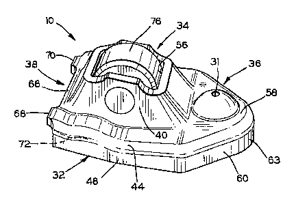
Fig. 2 is a view in perspective of the rocker arm o~ Fig. 1;
Fig. 3 is a top view of the rocker arm of Fig. 2;
Fig. 4 is a view in longitudinal cross section taken along
the lines 4-4 of Fig. 3; and
~~ Fig. 5 is a view in transverse cross section taken along
II the line 5-5 of Fig. 3.
Referring particularly to Fig. l, a rocker arm of the cam-
follower type is indicated at l0 and has one end portion received
on a rocker arm fulcrum or lifter post l2 extending upwardly
from a cylinder head l4 of an internal combustion engine. A
second end portion of the rocker arm engages upper ends of valve
s ems 16: The second valve stem is directly behind the one
shown and is not visible. The valve stems extend upwardly from
the cylinder head thxough coiled compression springs 18 located
therearound and which are seated against the cylinder head and
against retainer rings 20 mounted on 'the valve stems 16. An
overhead cam 22 engages an intermediate poxtion of the rocker
arm 10 to cause valves (not shown) located at the lower ends of
2S the valve stems 16 to open and close as the stems are moved
longitudinally by the rocker arm 10 as it is caused to pivot
by the cam.
SO ~~ -4-

...
The lifter post 12 is slidably carried in a chamber 24 of a
cylinder 26. The post is urged upwardly by oil under pressure
in the chamber 24. The oil is supplied through a small port 28
from a supply passage 30. The post 12 can yield somewhat when
05 ~~ the cam rotates, with the post moving downwardly slightly at
the high lobe of the cam 22 to provide a zero lash adjustment
for the rocker arm. The port is of a size to provide controlled
leakage of the oil from the chamber 24 to control the oil pres-
sure therein. 0x1 can also be supplied.from the passage 30 to a
~~ passage (not shown) in the lifter post 12 and up to an oil hole
31 in the rocker arm x0 for lubricating purposes.
Referring more particularly to Figs. 2-5, the rocker arm
l0 includes a one-piece, cold-formed metal body 32 which is
preferably made by cold-forming operations, including stamping,
extruding, coining; and back-packing. The rocker arm body
includes an intermediate portion 34 which engages the cam 22,
~a first end portion 36 which engages the lifter post 12; and
a second end portion 38 which engages the two valve stems 16.
The intermediate portion 34 of the rocker arm body includes
upright side walls 40 and 42 extending upwardly from flat walls
or webs 44 and 46. Short straight stiffening flanges 48 and 50
extend downwardly from and are structurally integral with outer
edges of the' webs 44 and 46. The intermediate portion 34 has end
walls 52 and 54 extending upwardly. The intermediate portion als
has a large, generally rectangular opening 56 formed at the upper
edges of the walls 40, 42, and 52, 54.
30.

~~ 2103771
The fixst end portion of the rocker arm body 34 has a wide
flat top wall 58 which is stxuctur ally integral and blends in wi
the webs 44 and 46 of the intermediate portion 34. Two slanted
stiffening flanges 60 and 62 extend downwardly from the flat
05 ~~ wall 58 and axe connected by a curved nose flange 63 which is
structurally integral therewith. A rounded recess 64 is formed
in the top flat wall 58 and faces downwardly to receive the
uppex end of the lifter post 12 on which the rocker arm 10 pivots
~~ The second portion 38 of the rocker arm body has a long,
narrow stiffening web 66 with projections 68 and 70 extending
outwardly from ends thereof. If desired, the web 66 can have a
downwardly-extendingw.flange for added stiffness. Rounded surfaces
72 and 74 form downwardly-facing pads at the second portion 38 to
engage the upper ends of the valve stems 16: These pads are
formed beyond the ends of the web 66 and near the projections 68
and 70. The pads~are also located under the webs 44 and 46 near
the ends of the downwardly-extending flanges 48 and 50:
The intermediate portion 34 of the rocker arm 10 rotatably
carries a cam-contacting roller 76 which is exposed at' the
opening 'S6 and contacts the overhead cam 22 to cause the rocker
arm to pivot on the post 12 when the cam 22 rotates. The use of
the roller minimizes friction between the cam and the rocker arm
which reduces loads and results in better fuel economy or higher
performance, as well as reduced. wear. The roller 76 is xotatably
mounted on an axle 78 which extends through two aligned circular
holes 80 in the side walls 40 and 42. The outer ends of the holes
-6-

-~~ 2103771
can have chamfers to xeceive flared ends of the axle to hold
the axle in position, as is known in the art.
From the above, it will be seen that the single rocker
05 arm 10 is all that is needed to operate two valves. This results
in lesser weight than if separate rocker arms were used. Also,
one less roller and one less cam lobe are required which reduces
costs and results in fewer moving parts and potentially less
maintenance problems. Further, space is saved in a direction
longitudinally of the engine which is often of critical
importance. With one less roller for the two valves, friction
can also be reduced.
Various modifications of the above-described embodiment
of the invention will~be apparent to those skilled in the art,
and it is to be understood that such modifications can be made
without departing from the scope of tl~e invention, if.they are
within the'spirit and the tenor of the accompanying claims.
' ' ' 25

Representative Drawing
A single figure which represents the drawing illustrating the invention.
Administrative Status

2024-08-01:As part of the Next Generation Patents (NGP) transition, the Canadian Patents Database (CPD) now contains a more detailed Event History, which replicates the Event Log of our new back-office solution.

Please note that "Inactive:" events refers to events no longer in use in our new back-office solution.

For a clearer understanding of the status of the application/patent presented on this page, the site Disclaimer , as well as the definitions for Patent , Event History , Maintenance Fee  and Payment History  should be consulted.

Event History

Description Date
Time Limit for Reversal Expired 2007-08-10
Letter Sent 2006-08-10
Grant by Issuance 2004-10-26
Inactive: Cover page published 2004-10-25
Inactive: Final fee received 2004-08-10
Pre-grant 2004-08-10
Notice of Allowance is Issued 2004-02-26
Letter Sent 2004-02-26
Notice of Allowance is Issued 2004-02-26
Inactive: Approved for allowance (AFA) 2004-02-11
Amendment Received - Voluntary Amendment 2003-11-27
Inactive: S.30(2) Rules - Examiner requisition 2003-05-28
Amendment Received - Voluntary Amendment 2000-10-06
Letter Sent 2000-08-17
Inactive: Status info is complete as of Log entry date 2000-08-17
Inactive: Application prosecuted on TS as of Log entry date 2000-08-17
All Requirements for Examination Determined Compliant 2000-08-02
Request for Examination Requirements Determined Compliant 2000-08-02
Inactive: Office letter 1998-06-10
Inactive: Office letter 1997-10-17
Inactive: Delete abandonment 1997-10-14
Deemed Abandoned - Failure to Respond to Maintenance Fee Notice 1997-08-11
Application Published (Open to Public Inspection) 1994-05-06

Abandonment History

Abandonment Date Reason Reinstatement Date
1997-08-11

Maintenance Fee

The last payment was received on 

Note : If the full payment has not been received on or before the date indicated, a further fee may be required which may be one of the following

  • the reinstatement fee;
  • the late payment fee; or
  • additional fee to reverse deemed expiry.

Please refer to the CIPO Patent Fees web page to see all current fee amounts.

Owners on Record

Note: Records showing the ownership history in alphabetical order.

Current Owners on Record
HENLEY MANUFACTURING HOLDING COMPANY, INC.
Past Owners on Record
JESSE V. MILLS
Past Owners that do not appear in the "Owners on Record" listing will appear in other documentation within the application.
Documents

To view selected files, please enter reCAPTCHA code :


To view images, click a link in the Document Description column. To download the documents, select one or more checkboxes in the first column and then click the "Download Selected in PDF format (Zip Archive)" or the "Download Selected as Single PDF" button.

List of published and non-published patent-specific documents on the CPD .

If you have any difficulty accessing content, you can call the Client Service Centre at 1-866-997-1936 or send them an e-mail at CIPO Client Service Centre.


Document
Description 
Date
(yyyy-mm-dd) 
Number of pages   Size of Image (KB) 
Representative drawing 1998-08-25 1 10
Claims 2003-11-27 4 124
Abstract 1995-04-08 1 34
Cover Page 1995-04-08 1 53
Claims 1995-04-08 5 196
Representative drawing 2004-02-12 1 14
Drawings 1995-04-08 2 56
Description 1995-04-08 6 225
Cover Page 2004-09-22 1 47
Reminder - Request for Examination 2000-04-11 1 117
Acknowledgement of Request for Examination 2000-08-17 1 178
Commissioner's Notice - Application Found Allowable 2004-02-26 1 161
Maintenance Fee Notice 2006-10-05 1 173
Correspondence 1998-06-10 1 6
Correspondence 1998-06-10 1 5
Correspondence 1998-05-20 6 153
Correspondence 2004-08-10 1 30
Fees 1996-07-05 1 37
Fees 1995-08-08 1 40