Note: Descriptions are shown in the official language in which they were submitted.
- 1 -
SELF=STANDING TOOTHBRUSH
FIELD OF THE INVENTION
The present invention relates to a toothbrush, and
more particularly to a toothbrush capable of standing in
a substantially upright position on a support surface.
BACpCGROOND OF THE INVENTION
Toothbrushes are generally stored after use in an
upright position to allow for the drainage of water.
Since most toothbrushes have relatively narrow handles,
they are not self-standing and are generally stored in a
toothbrush holder. The holder generally consists of a
support member having a plurality of holes or slots
adapted to receive and support the toothbrush handle in an
upright handle. These holders may be attached to a
bathrpom wall or medicine cabinet, or may be free standing
for placement on a countertop.
U.S. Patent No. 4,979,708 to Aoki describes a tooth-
brush holder far infants in the shape of an animated
character. The holder also contains a suction cup for
attaching the device to a flat surface.
U.S. Patent No. 1,465,642 to Keene describes a free-
standing toothbrush holder having a weighted base and a
flexible bushing for receiving the end of the toothbrush
handle opposite to the bristled head. U.S. Patent
No. 1,690,311 to Reich describes a similar holder having
an upstanding cylindrical member mounted on a weighted
base. The cylindrical member is large enough to receive
the bristled head and serves as a toothbrush cover during
travel. A resilient bushing is attached to the end of the
JDC-214
- 2 -
toothbrush handle opposite to the bristled head. After
use, this resilient bushing is inserted into the cylindri-
cal member and the brush is stored on an upright position.
U.S. Patent No. 1,899,242 to McNab describes a
toothbrush holder containing a suction cup which is
attached to the end of the handle opposite to the bristled
head. After use, the suction cup is simply attached to
the bathroom wall whereby the brush is stored in a sub-
stantially vertical position allowing for drainage. The
suction cup contains a head which fits within an aperture
formed in the end of the toothbrush. Alternatively, the
suction cup is part of an elastomeric sleeve which fits
over the toothbrush handle. Since the face of the suction
cup is in a plane substantially parallel to the toothbrush
handle, the cup must always be attached to a vertical
surface in order for the brush to be held in a vertical
position for draining. Thus, this holder is not suitable
for use on a countertop.
Suction cups have been used to support other articles
on a surface. U.S. Patent No. 1,587,874 to Sticklin and
U.S. Patent No. 2,588,990 to Sanchez, both describe the
use of suction cups on the bottom of dishes and other
receptacles to prevent against accidental tipping. U.S.
Patent No. 2,712,709 to Pulrang describes a soap dish
employing a suction cup as the mounting element.
U.S. Patent No. 1,892,140 to Folger describes the use
of a suction cup to support a collapsible tube, such as a
toothpaste tube, in an upright position on a countertop.
The collapsible tube is attached to the suction cup by
inserting the cap, which covers the threaded end of the
tube, into an aperture formed in the head of suction cup.
JDC-214
CA 02104047 2004-12-24
' 74327-61
3
Rechargeable, motorized toothbrush having a power
supply, motor and control circuitry housed within the handle
are known. These handles are generally larger than the
handles found on conventional toothbrushes. Some of these
handles have a flat bottom, which allows for the brush to
stand on its end. However, the brush is intended to be
stored in a separate housing containing the charging unit
for the rechargeable batteries.
It would be desirable to have a toothbrush which
is capable of being stored in a stable upright position
without the use of an anxiliary holder. These brushes would
be particularly useful in hotel bathrooms, where toothbrush
holders are generally not provided.
SU1~1ARY OF THE INVENTION
In a broad aspect the invention provides a
self-standing toothbrush, comprising: a head; a plurality of
bristles disposed on said head; a handle having a top
portion connected to said head and a bottom portion forming
a base; and means affixed to said base for enhancing the
stability of said toothbrush while disposed in a position
substantially perpendicular to a support surface, wherein
said means is a member dimensioned to enhance the stability
of said toothbrush while disposed in said upright position,
said member has a cross-sectional area greater than the
cross-sectional area of said base, and said member is
cup-shaped.
In another aspect the invention provides a
self-standing toothbrush, comprising: a bristled head; a
neck comprising a lower region and an upper region connected
to said bristled head; a handle having a top portion
CA 02104047 2004-12-24
74327-61
3a
connected to said lower region of said neck and a bottom
portion forming a base; said handle having a longitudinal
axis, said upper region of said neck and said bristled head
being angled relative to a line coincident with said
longitudinal axis; and a cup-shaped member comprising a head
and a rim, said head of said cup-shaped member being
permanently affixed to said base, said rim defining a
cross-section, and said cross-section being dimensioned to
enhance the stability of said toothbrush while disposed in
an substantially upright position relative to a support
surface.
BRIEF DESCRIPTION OF THE DRAWINGS
FIG. 1 is a side elevational view of the
toothbrush in accordance with the present invention shown
standing on a support surface.
FIG. 2 is a bottom perspective view of the
toothbrush of FIG. 1.
FIG. 3 is a bottom plan view of the toothbrush of
FIG. 1.
2~p~~fl~~
- 4 -
FIG. 4 is an enlarged fragmentary front view of the
handle portion ~f the toothbrush of FIG. 1.
FIG. 5 is a cross-sectional view of the handle taken
along line 5-5 of FIG. 4.
FIG. 6 is an enlarged fragmentary side view of the
handle portion of the toothbrush of FIG. 1.
FIG. 7 is a cross-sectional view of the handle taken
along line 7-7 of FIG. 6.
DETAINED DESCRIPTION OF THE PREFERRED EMBODIMENTS
Referring now to the drawings, where like reference
numerals have been used to designate like or similar
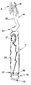
elements, there is shown in FIG. 1 a toothbrush of the
present invention having the general designation 10. The
toothbrush 10 is shown in a self-standing, substantially
upright position relative to a support surface. Tooth-
brush l0 contains a handle having the general designation
12, a neck 14 and a head 16 with a plurality of bristles
18.
The handle 12 contains a top portion 20 which is
connected via the neck 14 to the head 16. The handle 12
also contains a bottom portion 22 which forms a base. The
handle 12 contains non-slip surfaces 26 and 28 disposed on
opposed regions of the handle. The non-slip surfaces 26
and 28 contain a plurality of raised projections 27 which
form non-slip regions on the handle 12. These non-slip
regions are engaged by the user's thumb and fingers to
facilitate better manipulation of the brush. The non-slip
surfaces 26 and 28 as well as the projections 27 can be
configured in virtually any manner on the handle 12.
The neck 14 of the toothbrush 10 contains a helical
lower region 30 which is connected to the top portion 20
JDC-214
~1~~ 0~"~
- 5 -
of the handle 12. The neck 14 also contains an upper
region 32 which connects the helm?1 lower region 30 to
the head 16. The neck 14 is generally narrower than the
handle 12. The upper region 32 and the head 16 both lie
in substantially the same plane and are angled relative to
a line 1-1, which is coincident with the longitudinal axis
of the handle. This angle, identified by numeral 34 in
FIG. 1, is within the range of about 9-15° and preferably
about 12°. This angle gives the user improved access to
the distal teeth.
Turning now to FIGS. 2-3, the means for enhancing the
stability of the toothbrush l0 will be discussed in
detail. Preferably, the means is a cup-shaped member 24,
which is permanently affixed to the base 22 of the handle
12. The cup-shaped member 24 may take the form of a
suction cup, although other cup-shaped members not capable
of being vacuumed-attached to a surface may be employed.
The cup-shaped member contains a head 36 which is attached
to the base 22 of the handle 12. The cup-shaped member 24
also contains a rim 35 which engages a support surface
when the toothbrush 10 is placed in the self-standing
position. Although the wall of the cup-shaped member 24
in Fig. 2 extends outwardly from the head 36, other wall
configurations, such as cylindrical wall, may be employed.
The rim 35 of the cup-shaped member 24 defines a
cross-section having an area sufficient to stabilize the
brush 10. As shown in Fig. 2, the base 22 of the handle
12 has a cross-sectional area which is less than the
cross-section defined by the rim 35. The larger cross-
section defined by the rim 35 enhances the stability of
the brush 10. Further stability is achieved when the cup-
JDC-214
- 6 -
shaped member is a suction-cup, which is adhered to the
support surface.
While the means for enhancing the stability of the
brush 10 is shown in the form of a cup-shaped member 24,
it should be understood it may take on other configura-
tions so long as it enhances the stability of the tooth-
brush 10 while disposed in an upright position. For
instance, the rim 35 of the cup-shaped member 24 may have
a dimension, e.g., cross-sectional area or diameter, which
is less than or equal to that of the handle 12.
When the cup-shaped member 24 is a suction cup, the
brush 10 may be attached to a vertical surface, such as a
bathroom mirror, so that the handle is horizontally
disposed.
It is also advantageous in the present invention to
position the upper region 32 of the neck 14 and the head
16 so that they are disposed within a right cylinder
defined by the rim 35 of the cup-shaped member 24. If the
upper region 32 of the neck 14 and the head 16 extend
beyond this right cylinder, the toothbrush's center of
gravity moves horizontally away from the handle's longitu-
dinal axis and the brush may become unstable. As shown in
FIG. 1, by terminating the helical lower region 30 of the
neck 14 on the side of the toothbrush adjacent the non-
slip surface 26, the upper region 32 and the head 16 can
be disposed at an angle relative to the line 1-1, but
still reside within the right cylinder defined by the rim
of the cup-shaped member 24.
The handle 12, neck 14 and head 16 of the toothbrush
10 may be molded from a thermoplastic polymer, such as
JDC-214
styrene-acrylonitrile, copolymers, polypropylene, cellu-
lose acetaLP, cellulose acetate propionate, and poly-
methylmethacrylate. The handle 12, neck 14 and head 16
may be molded in conventional injection molding equipment.
The bristles 18 are inserted into the head 16 using
conventional bristling equipment e.g., Boucherie,
Zahoransky or Evans machines. The bristles 18 are fabri-
cated from various plastic materials such as polyamides,
polefins, polyesters or natural fibers, such as animal
hair. Preferably, the bristles 18 are nylon.
The non-slip surfaces 26 and 28 may be fabricated
from an elastomeric material such as neoprene, silicone
rubber or RTV silicone, and preferably from a thermoplas-
tic injection moldable rubber, such as SANTOPRENE~ rubber
from Monsanto Chemical Company. These parts may be
fabricated, ssch as by molding, in a separate operation
and then attached to the handle 12 with an adhesive or be
formed as interlocking parts which are snapped into place.
Alternatively, the non-slip surfaces 26 and 28 may be
injection molded into a series of voids formed in the
handle 12. This aspect will be disclosed in more detail
in reference to FIGS. 4-7.
The cup-shaped member 24 may be fabricated from the
materials used to form the handle 12, neck 14 and head 16,
or from the above-described elastomeric materials used to
fabricate the non-slip surfaces 26 and 28. When the cup-
shaped member 24 is a suction cup, it is fabricated from
an elastomeric material so that it has sufficient flexi-
bility to be compressed and create a vacuum. The cup-
shaped member 24 may be formed in a separate manufacturing
step from the handle 12 and then glued or mechanically
JDC-214
~i~~~ ~'7
_8_
affixed to the base 22 of the handle 12. The cup-shaped
member 24 may also be fabric~t~d simultaneously with the
molding step used to form the non-slip surfaces 26 and 28
described below.
Commercially available, fully automated processes for
forming toothbrush handles from separate or different
colored materials may be used to fabricate the toothbrush
of the present invention. One such process is described
in an article entitled "Zahoransky's Fully Automated Two-
Color Mold", Brossa Press, 1989. In the first step of the
process, the plastic material which forms the bulk of the
toothbrush 10, i.e., the handle 12, neck 14 and head 16,
is injected into the cavity of the mold. The resulting
structure is a partially formed toothbrush having a handle
with a series of void spaces. The partially formed
toothbrush is then moved into a second cavity within the
same mold where a second or different colored material is
injection into the void spaces to complete the toothbrush
handle. The second mold cavity is contoured so that the
non-slip surfaces 26 and 28 and the cup-shaped member 24
are formed during the second molding step. Generally the
first material forming the bulk of the toothbrush is
polypropylene, while the second material is SANTOPRENE~
rubber. The same material, but colored with two different
pigments, may also be used in the process to from a multi-
colored toothbrush.
Turning now to FIGS. 4-7, the handle 12 formed from
two different materials will be described in detail. As
shown in FIGS. 4 and 5, the bulk of the handle 12 is
fabricated from a polypropylene material 38. The non-slip
regions 26 and 28 and the cup-shaped member 24 are fabri-
cated from a thermoplastic rubber 40. As shown in FIG. 5,
JDC-214
- 9 -
the handle 12 contains a series of cavities 42 and 44
~ahich extend through the handle 12 and are filled T;-ith the
thermoplastic rubber 40. During the molding process,
molten thermoplastic rubber also flows toward the base
portion 22 through a pair of slots 46 and 48. The molten
thermoplastic rubber flowing through the slots 46 and 48
fills the portion of the mold cavity contoured to form the
cup-shaped member 24.
Example
In order to demonstrate the enhanced stability which
is achieved with the toothbrush of the present invention,
a series of toothbrushes were tested for their stability
when standing in an upright position on a flat, horizon-
tally disposed support surface.
Test 1
The toothbrush in FIG. 1 was fabricated using a
process similar to that described in the article entitled
"Zahoransky's Fully Automated Two-Color Mold". The bulk
of the brush was fabricated from polypropylene, while the
non-slip surfaces 26 and 28 and the cup-shaped member 24
were fabricated from SANTOPRENE~ thermoplastic rubber.
The diameter of the rim 35 of the cup-shaped member 24 was
approximately 1.6 cm and the brush length was approximate-
ly 15.8 cm. The brush was then placed on end in a self-
standing position. No downward force applied to the
brush, so there was no suction created between the cup-
shaped member 24 and the support surface. A horizontal
force was applied to the tip of the toothbrush head and
the brush tipped over after having been deflected approxi-
mately 8°, relative to vertical.
JDC-214
'~ ~. ~ ~ ~ ~'~
- 10 -
Test 2
T~~t 1 was repeated, except that a downward force was
applied to the brush so as to create a suction between the
cup-shaped member 24 and the support surface. When the
horizontal force was applied to the brush in this configu-
ration, the suction broke after about 4° of deflection and
the brush tipped over after having been deflected about 8°,
both relative to vertical. The force required to break
the suction between the cup-shaped member and the support
surface was significantly greater than the force used to
tip the brush aver in Test 1.
Test 3
Test 1 was repeated, except that the cup-shaped
member 24 was removed from the brush depicted in FIG. 1 so
that the flat polypropylene base 22 was left exposed. The
flat base 22 was then placed on the support surface so
that the brush was disposed in a self-standing position.
When the horizontal force was applied, the brush tipped
over after having been deflected about 3 to 5° relative to
vertical.
The above results demonstrate that the cup-shaped
member substantially enhances the stability of the tooth-
brush when it is disposed in a substantially upright
position relative to the support surface. The toothbrush
containing such a member can be deflected to approximately
8° relative to vertical, whereas the brush having only a
flat base tipped over after being deflected about 3 to 5°
relative to vertical.
The foregoing description and drawings are intended
to be illustrative of the present invention. Various
changes and modifications can be made to the above-de-
JDC-214 --
- 11 -
scribed embodiments without departing from the spirit and
scope of the present invention.
10
20
30
JDC-214