Note: Descriptions are shown in the official language in which they were submitted.
.L ti ':.~ U ~ ~ Cr> f .> : ~ ~ w; . .
"Express Mail" Mailing Label No. 81.25563944) Date of Deposit 3/09/93
I hereby certify that this paper or fee is being deposited with the United
States Postal Service "Express
Mail Post Office to Addressee" service under 37 CFR 1.10 on the date indicated
above and is addressed to
the Commissioner of Patents and Trademarks, Washington, D.C. 20231
Roger w. Erickson
POLYC
6944
METHOD AND APPARATUS FOR RECOVERING
MULTICOMPONENT 'VAPOR MIXTURES
Specification
0 This invention relates to a method and apparatus for
recovering multicomponent vapor mixtures, and more
particularly for recovering vapor mixtures used in
sterilizing processes.
Backcrround of the Invention
In various industrial processes multicomponent vapor
mixtures are used and after their use it may be necessary
or highly desirable to capture and recover such mixtures
for reuse or to prevent the escape of particularly
contaminating constituents to the atmosphere. For example,
many hospitals and some industrial manufacturing processes
employ a process called gas sterilization which comprises
the following steps: (1) A pressure and vacuum sealed
enclosure or vessel is loaded with articles to be
sterilized. The sterilizer and its contents are
preconditioned by evacuation down to a moderately low
pressure level, typically about 75 Torr (26 in. Hg Vac.),
backfilled with low pressure steam and then re-evacuated.
This evacuation-backfill cycle is repeated several times to
remove most of the air and to prewarm and moisten the
articles to be sterilized. (2) A sterilant gas, typically
a 12-88 weight percent mixture of ethylene oxide and CFC-12
(dichlorodifluoromethane), is introduced into the
preconditioned and evacuated enclosure until the pressure
reaches approximately 1; atmospheres. This condition is
held for a predetermined period adequate to sterilize the
articles in the enclosure. Heretofore, the now moist
sterilant gas was removed from the enclosure by evacuation
and was either discharged into the atmosphere or the sewer.
This practice created serious problems. First of all,
~~i~vt~Ja °
ethylene oxide by itself is flammable, explosi~re and toxic,
while the blanket vapor, dichlorodifluoromethane or CFC-12
damages the ozone layer in the atmosphere and is a global
warming gas. Therefore it became desirable, if not
essential, to provide a process for capturing and
recovering at least the CFC and preferably both components
of the mixture.
The aforesaid problem of capturing the vapor
constituents from a sterilizer were further aggravated by
the fact that after the initial post-sterilization
evacuation step, a continuous air flow at a controlled flow
rate was normally introduced into the sterilizer and
maintained at slightly below atmospheric pressure. This
air wash stream absorbed sterilant gases which desorbed
from the sterilized articles and the enclosure's surfaces.
Following the previous air wash step, the air flow was
stopped, the enclosure evacuated (again, to the atmosphere)
and then backfilled with air to slightly less than
atmospheric pressure, This air pulse cycle, with a pause
each time after backfilling with air, was repeated for a
number of cycles or a period of time until the sterilized
articles were satisfactorily outgassed. "
Because of the explosive potential and toxic risks of
ethylene oxide and the ozone depleting characteristics of
CFC-12, a satisfactory method for recovering and preventing
the release of such sterilizing vapor mixtures became
imperative.
The use of several known, conventional types of
apparatus and methods for recovering, disposing or
otherwise handling multicomponent vapor mixtures have
serious disadvantages and have been considered'to be
impractical.
For example, a procedure entailing the vapor
compression then cooling of the vapor mixture to condense
it has been suggested. However, in order to attain a high
capture rate of around 99%, mechanical evacuation and
compression of vapor reguires a very high pressure ratio,
2
~~i~ivtJJJ
in excess of 100 to one. High pressure ratios create high
discharge temperatures. This may cause deleterious effects
when compressing mixtures containing chemically unstable
components such as ethylene oxide. This method also lacks
the inherent ability to separate significant amounts (more
than a few percent ) of non-condensible gases such as air
at allowable release rates for captured materials. Also,
the pumping system may introduce lubricants or other
contaminants into recovered materials and requires a high
energy input. Therefore, this vapor compression procedure
is now used only for those sterilizers which do not employ
air for back-filling or air washing but use steam only.
Another suggested method for handling vapor mixtures
involved membrane separation of selected vapors. However,
membranes are limited to separating specific vapors and
must be combined with other technologies, such as catalytic
destruction or chemical scrubbing, to adequately process
mixtures for desired recovery. Also, their useful life may
be limited and require periodic replacement.
Similarly, the use of sorption onto charcoal or
molecular sieves has been considered, but sorption, at
ambient, low or cryogenic temperatures, has similar limits
as those for membranes. Sorbents can become polluted or
create acidic conditions and hence less effective over a
number of cycles of use arid require significant maintenance
or replacement.
Cryogenic condensing and separation of recyclable
materials was another possible approach to the problem of
handling vapor mixtures. However, expendable cryogens,
e.g. liquid nitrogen, require special transportation,
handling and sometimes logistics problems, thereby
entailing high operating costs, and some attendant safety
risks. Such cryogens also require supplemental separation
techniques particularly for removal of components which
freeze well above nitrogen's boiling point.
Catalytic destruction of combustible components is
another vapor handling technique, but catalytic disposer
3
-1 ~iii~~~l
units can only remove combustible portions of mixtures and
therefor must be used in combination with uther apparatus
such as membranes or scrubbers. Also, they cannot dispose
of nor convert CFCs into benign materials, and the method
in general requires a high energy input.
Chemical (typically acid) scrubbing of vapors to
remove and render benign selected components is a well know
process used for vapor control, but scrubbers remove only
those components with which the chemical reacts. Other
components such as halocarbons require additional apparatus
for recovery.
In summary, all the above prior methods and apparatus
considered for handling the moist vapor mixtures such as
those used in sterilizers entailed serious disadvantages
and failed to solve the prablem.
It is therefore.one object of the present invention to
provide an apparatus and method for capturing
multicomponent mixtures existing only in a vapor phase,
including ozone depleting and possibly hazardous materials,
and for recovering and/or recycling, such mixtures
comprising condensible vapors, non-condensible air,
moisture or their contaminants.
Another object of the invention is to provide an
apparatus for recovering multicomponent vapor mixtures
which significantly reduces the required energy input (by
at least 50% compared to a single cryogenic temperature
capture system) while retaining a capture efficiency of at
least 99% for a vapor mixture such as OxyFume-12 (88% R-12
and 12% by weight ethylene oxide) starting at a dew point
as low as -15 C and mixed with water vapor and air.
Another object of the invention is to maintain a safe
balance between the blanketing vapor and the toxic or
hazardous components of a mixture, e.g. the R-12 and
ethylene oxide of the above example, during all stages of
capture.
Other obj ects of the invention are to provide a method
and apparatus for recovering multicomponent vapor mixtures
4
~.I~li-3i.'JJ
which: (1) separates benign non-condensible gases (e. g.
air) from recyclable materials and safely disposes of such
gases without an unacceptable release of captured
componentss (2) extracts hazardous, environmentally
undesirable or valuable vapors from their point of use and
transfers them in either liquid or vapor phases as
required, from the recovery system to vessels for transport
and reclamation, without using mechanical pumping means
that might introduce contamination; (3) provides a capture
efficiency of at least 99% for a mixture comprising 88%
(weight) CFC-12 and 12% ethylene oxide; and (4) is able to
operate properly under any of three distinct modes: (a)
Evacuating the source enclosure from an initial pressure of
one to two atmospheres, when it contains almost all
condensible materials with little non-condensible air
present, down to a vacuum; (b) Pumping out (evacuating) the
source enclosure after it has been backfilled with air, the
air serving as a carrier gas for bath the residual vapors
in the apparatus and vapors desorbed from products within
the apparatus, and therefore to separate and capture
condensible vapors at a low concentration in the mixture,
and (c) Removing condensible vapors from a steady flow of
a carrier gas, typically air, flowing at a steady rate from
the source enclosure to the recovery system; and comprising
a compact integrated recovery system capable of achieving
the above objectives at lower total (acqui.sition,
installation and operating) cost and lower energy
requirements than other prior art technologies.
Brief Summar~r of the Invention
In accordance with the principles of the invention the
aforesaid objects are accomplished by an apparatus which
can be connected directly to a chamber such as a medical
instrument sterilizer which contains the vapor mixture that
is to be recovered. An outlet conduit from the mixture
chamber or sterilizer has a first branch conduit through a
capture valve to a first level cooling tank or cold trap.
5
This outlet conduit also connects to one side of a
precondition valve whose other side is connected to a '
vacuum pump. Between the precondition valve and the vacuum
pump is another branch conduit connected to a second
cooling tank or cold trap, preferably at a lower level.
The upper end of the first cooling tank or cold trap is
connected by a vapor transporting conduit to the second
cooling tank. The lower end of the first cooling tank is
connected to a conduit which transports condensate by
l0 gravity flow to the second cooling tank. The first cooling
trap has an internal coil or cooling surface which is
cooled by a first outside refrigerant source to an
operating temperature range of -5 to -40 C and the second
cold trap assembly has an internal coil which is cooled to
a range of -95 to -110 C. After a normal sterilization
process wherein the. sterilizer is filled with a vapor
mixture of steam, ethylene oxide and CFC-12, the vapor
mixture is drawn directly into the .apparatus by a cryo
pumping action and a vacuum pump. With the preconditioning
valve closed arid the capture valve open, the moist
sterilant vapor mixture flows into the first cold trap
which is at a low pressure. Volatile vapors start
condensing on the coil of the first cold trap and the steam
condenses as frost. The sterilant vapor, a mixture of two
compounds, partially condenses within the first cold trap.
The condensate formed in the first cold trap is drained
into the reservoir section of the second trap. The colder
coil or cryosurface in the second trap induces flow of
uncondensed vapor from the first cold trap to the second
cold trap arid this vapor is ultimately condensed on the
colder coil. The condensed vapor from this coil blends
with the condensate from the first trap in the reservoir of
the second trap and hence the condensed sterilant mixture
promptly returns to its original safe ratio of the blanket
material, CFC-12, to ethylene oxide. Thus, this
reconstituted mixture can be transported for reuse without
being dumped into the atmosphere.
6
~.~1~':tt7~~
Other objects, advantages and features of the
invention will become apparent from the following detailed
description of a preferred embodiment thereof, presented in
conjunction with the accompanying drawing
Brief Description of Drawing
The attached drawing is a diagrammatic representation
of an apparatus embodying principles of the invention.
Detailed Description of Embodiment
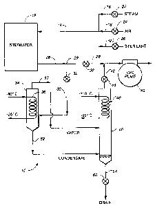
With reference to the drawing a recovery apparatus 10
is shown which withdraws a multicomponent vapor mixture
from a processing chamber which, in the example shown, is
a gas sterilizer 12. Such sterilizers are commonly used in
hospitals and laboratories for sterilizing surgical
implements and the like. In use, as previously described,
the sterilizer is filled with a sterilant gas, typically a '
12-88 weight percent mixture of moist ethylene oxide and
CFC-12 (dichlorodifluoromethane). As described below, the
apparatus 10 functions to remove and recover the gas
mixture from the sterilizer and to provide a condensate end
product comprised of the original mixture constituents in
substantially the same proportions as when first supplied
to the sterilizer.
Connected to the sterilizer 12 is an input conduit 14
which in turn is connected to three supply inputs 16, 18
and 20 for admitting either steam, air or sterilant to the
sterilizer. Each input has its own supply valve 22, 24 or
26 for controlling flow from a separate supply source (not
shown) .
An output fluid conduit 28 extends from the sterilizer
to carry the moist gas mixture from it. This conduit is
connected through a first or precondition valve 38 to a
vacuum pump 40. Branching from conduit 28 at a junction 29
is a conduit 30 which passes through a controllable second
or capture valve 32 and extends to a first cooling chamber
or trap 34. This trap has within it a coil 36 providing a
7
~;.9.~i~~U~~
cooling surface, the ends of whic.:h extend out from the
cooling trap 34. The ends of 'the coil 36 are connected to
a suitable refrigerant source (not shown) which is capable
of supplying refrigerant to the coil in a temperature range
of -5 to -40 degrees C. Such a refrigeration source may be
an apparatus such as shown in 'U. S. Patent No. 3,768,273.
At a short distance from the junction 29, the conduit
28 is connected through the precondition valve 38 and
thereafter to the vacuum pump 40. Connected to the conduit
28 between the valve 38 and the pump 40 is a branch conduit
42 which extends through a third valve 44 from a second
cooling chamber or trap 46. This trap is preferably
situated lower than the first cooling trap 34. Within the
trap 46 is a cooling coil 48 whose ends extend outside the
trap to a refrigeration source (not shown) which furnishes
refrigerant to the cool 48 at a temperature range of -95 to
-110 degrees C. Such a refrigeration source may be of the
type shown in the previously mentioned U.S. Patent.
A conduit 50 for carrying vapor from cooling trap 34
is connected to the upper end thereof and extends to
cooling trap 46, preferably at a location just below its
cooling coil 48.
To the bottom end of the cooling trap 34 a conduit 52
is connected for carrying condensate therefrom. The other
end of this condensate conduit is connected to the lower,
colder cooling trap 46 near its bottom or reservoir end so
that condensate will flow from trap 34 to trap 46 by
gravity.
Extending from the conical or dished shaped lower end
of cooling trap 46 is a conduit 54 having a drain valve 56
for removing the reclaimed condensate from the apparatus
10.
The detailed operation and method employed by the
apparatus 10 will now be described together with an
explanation of a typical sterilization process.
Sterilization process: For preconditioning,
sterilizer 12 first is evacuated by vacuum pump 40 via
8
~1~U=~~JJ~
conduit 28 and through precondition valve 38. Following
this, valve 38 then is closed. Steam is now admitted into
sterilizer 12 via conduits 16 and 14 through valve 22.
When sterilizer 12 reaches a predetermined pressure, steam
valve 22 is closed and preconditioning valve 38 is reopened
for a repeat of the evacuation step. After several such
cycles and then a last evacuation step, valve 26 opens to
admit sterilant gas into sterilizer 12 via conduits 20 and
14 until the sterilant's pressure reaches a predetermined
pressure equivalent to a dew point of about -10 to -15 C.
The gas then sterilizes the implements or products therein.
After the sterilization cycle, the recovery system begins
its capture of the gases and vapors for reclaiming and
recycling. '
Capture System Preconditioxaing: During or before the
sterilizer's preconditioning and sterilizing steps,
trapping (condensing) coils or surfaces 36 and 48 in cold
trap assemblies 34 and 46 are precooled to operating
temperature levels, between -5 to -40 C and -95 to -110 C
respectively. Vacuum pump 40 purges air from cold trap
assemblies 34 and 46 via conduit 42 and evacuation valve 44
any time a significant amount of air accumulates.
Air Purge: Accumulated air is detected by (a)
measuring the temperature of cryogenic surface 46, (b)
calculating the sterilant's vapor pressure at this
temperature and (c) comparing this pressure to the pressure
within cold trap assembly 46. The difference between the
pressure in the cold trap and the vapor pressure at
cryosurface temperature of cryosurface 46 indicates the
partial pressure of air present. Vacuum pump 40 withdraws
the air via conduit 42 and through evacuation valve 44
until the two pressures are near each other. The evacuated
air carries only trace amounts of sterilant vapor out of
cold trap assembly 46 to the vacuum pump 40 because of the
cryogenic temperature and geometry of the cryosurface 48
which permits only minimal bypass flow.
Capture cycle: After the sterilizer 12 completes its
9
~~.U~~1~5
sterilization cycle and with supply valves 22, 24 and 26
preconditioning valve 38 closed, the capture valve 32 is
opened. A mixture of moist sterilant vapor and residual
air flows from the sterilizer 12 via conduits 28 and 30
into cold trap assembly 34 which is at low pressure.
Volatile vapors start condensing on the cryosurface 36.
Almost all of the steam (water vapor) condenses in the form
of frost on surface 36. The sterilant vapor, a mixture of
two compounds which do not form an azeotrope, partially
condenses. The condensate is richer in the higher boiling
component, ethylene oxide, and vapor is richer in the more
volatile (lower boiling) component, typically a blanketing
vapor such as CFC-12. The condensate formed in cold trap
34 drains via conduit 52 to the reservoir section of cold
trap 46. Cryosurface 48 in cold trap 46, which is at a
very low temperature, induces flow of the uncondensed vapor
and residual air from cold trap 34 via conduit 50 to cold
trap 46. There this vapor condenses on cryosurface 48 and
drops into and blends with the condensate from cold trap 34
in the reservoir section of cold trap 46. Thus, the
condensed sterilant mixture promptly returns to its
ariginal safe ratio of CFC-12 to ethylene oxide.
Air Pulses Capture valve 32 is closed to isolate
sterilizer 12 from the capture system. Air admitting valve
24 is opened to backfill sterilizer 12 with air to nearly
one atmosphere pressure and then is closed. Sterilant
vapor and moisture, now desorbing from the sterilized
products and the walls of the sterilizer 12, diffuse into
the air. After a predetermined time, air admitting valve
24 is closed and capture valve 32 is opened. The capture
system then removes this air and moist sterilant mixture in
the same manner as described above except that the fluid
flowing is now principally air. Cold trap 34 precools this
fluid stream to almost the temperature of cryosurface 36
with little or no condensation of volatiles because of
their low partial pressure. This fluid stream flows via
conduit 50 to cold trap 46 where its cryosurface 40 removes
.. k
., , ,
' ' ~,:. ~ ~... .
~.y 5 .. .
. ~ ..~. .
.. . . . . ..,. . ~ ~ . '.: . - ; , , ..
~,.Lt~~~3J~
by condensation volatile vapors due to its very low
temperature. Vacuum pump 40 removes the air, now
essentially free of sterilant, via conduit 42 and through
evacuation valve 44. A predetermined number of these air
pulse cycles may be repeated or an air wash cycle may
follow.
Air Wash: This cycle is similar to the air pulse
described above except that when the sterilizer 12 is
backfilled with air until it reaches a pressure just below
one atmosphere, air admitting valve 24 remains open when
the capture valve 32 is opened. A controlled flow of air
flows into the sterilizer and vacuum pump 42, with
evacuation valve 44 open, operates continuously for a
predetermined period. This optional process provides a
flushing process for removal of absorbed sterilant from
sterilized products and sterilizer 12. Air admitting valve
24 closes at the end of the air washing period and the
capture system and vacuum pump 40 continue to operate for
removal of residual air and vapors from sterilizer 12.
Additional air pulse cycles may follow the air wash cycle
as determined necessary to remove residual sterilant vapors
from sterilizer 12 and the sterilized products therein.
Recovery and Transfer: After completion. of the
capture processes, capture valve 32 and air purge valve 44
are closed to isolate the captured moist sterilant
condensate within the capture system. The condensate in
the reservoir section of cold trap 46 and cryosurfaces 36
and 48 are heated to above room temperature until the
pressure of the condensate increases to.a suitable level
for transfer. The heat source can be electric resistance
heaters. A preferred embodiment is a modified version of
U.S. Patent No. 4,535,597. This arrangement utilizes heat
rejected from the cooling system to quickly reheat a
cryogenic surface. (See Cooling System described below).
A transport cylinder, not shown, is connected to drain
valve 56. Drain valve 56 and' the cylinder's valve are
opened to allow transfer of the now warm (moist and used)
11
1~~.(t iUJJ
sterilant liquid via conduit 54 from the capture system to
the cylinder. Drain valve 56 and the cylinder valve are
closed and the capture cycle is ready to be repeated.
Energy Savings: Dividing the cold trapping process
into two temperature levels or steps reduces the required
input power by at least one-half. Energy is saved because
a large portion of the heat load for condensing the mixture
is handled at warmer temperatures. More than one-half the
sensible and latent heat (cooling) energy required for the
total cold trapping effect is above about -30 C with the
remainder between -30 C and -95 to -105 C. The input power
required for the same refrigeration effect at the colder
level of about -100 C is three times as great as at the
warmer level of -30 C.
Safety and Condensate Management: Trapping in two
steps creates two ,condensate streams. It might be .:
considered more logical to keep these condensate streams
separate until transferring the captured materials into
storage or shipping containers, However, ethylene oxide is
a hazardous material and will burn or explode when exposed
to air and not mixed with enough blanketing gas to make the
mixture safe. The arrangement of the present invention
which provides two temperature level trapping serves to
fractionate the CFC-12 and ethylene oxide mixture causing
condensate from the warmer trap to be rich in ethylene
oxide and that from the colder trap to be rich in CFC-12.
Thus, a hazardous situation could exist if air somehow was
mixed with the condensate from the warmer trap. This
potential problem is solved in a novel. way by promptly
draining this condensate into the colder trap where the two
condensate streams mix and the remaining vapors are rich in
the blanketing material. The extra cooling required to
subcool the warmer condensate to the colder trap
temperature is not significant because it is only sensible
heat without a phase change. In this manner, a safe
balance of the component materials is maintained throughout
the two step trapping process.
12
~;i~risaJ
Cooling System: A number of refrigerating systems can
be employed for refrigerating the cold traps 34 and 46 in
this trapping system 10. Expensive expendable cryogens
require constant transport and handling and therefore are
not best suited. A single stage vapor compression
refrigerator can cool the -3U C trap and a conventional
multi-compressor cascade system can, with difficulty,
produce the necessary cooling for the -95 to -110 C trap.
A preferred cooling system is described in U.S. Patent No.
3,768,273. Fig. 1 in this patent illustrates two
refrigerant evaporators, 28 and optional 51, which operate
' at lowest and intermediate temperatures respectively. Such
a system provides the required cooling and, when modified
as mentioned the Recovery and Transfer section above, it
can provide the required reheating for transfer of the
captured materials.. In this manner, no mechanical pumps
are needed to move and possibly contaminate captured
sterilant.
While the foregoing apparatus 10 is particularly
adapted for reclaiming a sterilant gas mixture, the
principles of the present invention could also be applied
for reclaiming gas or vapor mixtures with various
constituents used in other devices.
To those skilled in the art to which this invention
relates, many ali~anges in construction and widely differing
embodiments and applications of the invention will make
themselves known without departing from the spirit and
scope of the invention. The disclosure and the description
herein are purely illustrative and are not intended to be
in any sense limiting.
WHAT IS CLAIMED IS:
13