Note: Descriptions are shown in the official language in which they were submitted.
W092/17~8 PCT/GB92/~K24-
- 210~212
P~OTO~TC ~Pr.TFI~R
This invention relates to photonic amplifiers
and especially to photonic amplifiers which are
intended for use in a long series of amplifiers.
Such series are used in telecommunications, e.g. in
optical submarine cable systems, and it is desirable
that such systems should include provision to
indicate the probable location of certain faults.
Specifically it is desirable to provide for the
approximate location of a broken link which, of
course, completely terminates any communication
across the break. Clearly, a break implies that
signal levels fall to zero. In addition to the
breakage of a link, a similar condition occurs due
to the deterioration of components. Thus, the
failure of an amplifier would be equivalent to a
break, and the deterioration of an amplifier would
result in loss of gain whereby signal levels might
fall to an unacceptably low level. Conditions such
as the total loss of signal would probably be
noticed in any system. However the location of the
fault may not be apparent in a larger system and it
is the object of this invention to provide
information which helps to locate a fault.
A photonic amplifier amplifies optical signals
using laser action, that is, signal photons
stimulate the emission of similar photons whereby
the signal is amplified. It is convenient to
distinguish between two types of photonic amplifier
by reference to the nature of the lasing medium. In
the first type, the lasing medium is a semi-
conductor and the amplifier has a complicated
~1~4~1~ PCr16B9 ~ / O O S 24
il9 FEBRUARY ~3
-- 2
structure involving several functional regions and
interfaces. In the case of a semi-conduc'tor
amplifier, the power to drive the amplification is
provided by an electric current from a suitable
electronic circuit. In the second type of
amplifier, the lasing medium is an optical fibre
which is doped with a lasing species such as Nd or
Er. In the case of a fibre amplifier, the power for
the amplification is provided in the form of pump
radiation which may have a shorter wavelength than
the signal radiation. The pump radiation produces
a population inversion in the lasing species in
accordance with the well known theory for the
operation of lasers.
In accordance with this invention a photonic
amplifier which includes a detector means and a
distress transmitter, the' ~aid- detector means
capable of detecting valid signals which include a
control tone modulated onto a traffic signal, in
normal operation, on receipt of valid signals the
detector means is adapted to disable the distress
transmitter, and the distress transmitter when
enabled to provide to an output of the amplifier an
optical distress signal which is recognisable as a
valid signal and which is modulated with information
which includes the identity of the amplifier. More
speci~ically, the default condition occurs when the
~ignal level falls to an unacceptably low level. As
mentioned above, the case where the signal falls not
merely to a low level, but to zero is of particular
interest. In accordance with the invention, a
photonic'amplifier, for use with signals modulated
with a control tone, wherein the detector means is
configured to disable the distress transmitter when
p~ r~lè.; r~ltlo~ Al~ at~~n
210~212 P~T16B 9 2 / 0 ~ 5 ~4
1~ FEBRU~RY 1993
- 2~-
control tone above a predetermined level is
detected, and to enable the distress transmitter
when control tone below the predetermined level is
Un~ Jom Pa~in~ O~lce ~t-~5~3~
W092/17~ 2 1 0 ~ 2 12 PCT/GB92/~24
detected, and wherein the distress transmitter
produces a distress signal modulated with control
tone such that said distress signal disables the
distress transmitters of similar amplifiers, to
which the amplifier may be connected. The distress
signal adopts the same signal format as the normal
signal so that subsequent amplifiers remain in the
normal configuration. It should be understood that
normal traffic signals are digitally modulated, and
therefore the distress signal can also be digitally
modulated. According to another aspect of this
invention the distress signal is digitally modulated
with the identity of the originating amplifier in
order that the location of the fault is at least
partially indicated. It is emphasised that, because
the distress signal adopts the same signal format as
the normal signal, only one amplifier of the series
will adopt the distress mode and this simplifies the
decoding of the distress information modulated onto
the distress signal.
Usually an amplifier includes an automatic gain
control, i.e. AGC. An AGC is generally used because
it is good engineering practice to maintain the
output of an amplifier at a predetermined level. If
the level of the received signal falls, e.g. if any
of the faults mentioned above occur, there is a
danger that the AGC will be driven into an overload
condition as it tries to achieve the impossible. It
is therefore good practice that an AGC be provided
with overload protection in order to reduce the risk
of damage to any of the circuitry. For the purposes
of the present invention, it is possible to utilise
the overload protection of the AGC as the indication
of the default condition. According to one
W092/17~ 21 0 ~ PCT/GB92/~K24
-- 4
embodiment of this invention the distress signal is
initiated when the overload protection of the AGC
comes into operation. In a second embodiment the
distress signal is initiated when the input to the
AGC falls below a preset level.
Many optical telecommunication systems utilise
a control tone which is a low frequency signal which
is amplitude modulated onto the optical signal in
addition to the digital modulation to carry the
traffic. Frequencies of a few kilohertz, e.g. 5 -
30 KHz, are suitable for use as the control tone.
One of the reasons for using the control tone is
that there can be several optical signals present in
the system. For instance it is possible that the
system may contain optical noise as well as the
opticai signal and, in a default case, all the
optical energy may be noise. It can be difficult to
distinguish one optical signal from another and the
detection of the control tone provides a convenient
way of recognising that the traffic signal is
present, and measuring the level of the control tone
is a convenient way of measuring the level of the
traffic signal. In fact, the AGC of many fibre
amplifiers operates by keeping the level of the
control tone constant, rather than by acting
directly on the signal. At the originating station,
the ratio of modulation to traffic signal is
maintained constant, and under these conditions
maintaining a constant level of control tone has the
effect of maintaining a constant traffic signal
level. With systems of this nature the AGC will
saturate if the level of the control tone drops and
this saturation will initiate the default condition
described above. In other words the distress mode
WO92/17~ . PCT/GB92/~K24
210~12
is initiated when the level of the control tone
drops to an unacceptable level. It will be
appreciated that it is also possible to actuate the
distress mode by direct measurement of a control
tone, as well as the indirect techni~ue of relying
on the AGC. EP Patent Specification 331 304
describes an AGC for semi-conductor amplifiers.
This AGC operates without breaking into the optical
circuit, and it mentions the use of a control tone
which is modulated onto the optical signals.
As mentioned above, it is an important feature
of this invention that the distress signal has the
same format as the normal signal. In the case of a
system which uses a control tone it is, therefore,
important that the distress signal be modulated with
the same control tone as is used in a normal signal.
Subsequent amplifiers, which receive the distress
signal, will therefore receive a normal control tone
and they will therefore remain in the normal
configuration. EP Patent Specification 331304
(mentioned above) has a default configuration in
which the semi-conductor amplifier provides a
distress signal when the traffic signal becomes
unacceptably weak. However the normal control tone
is not utilised in the distress configuration, and
therefore all subsequent amplifiers adopt a distress
configuration. This is an important difference
between the distress configuration described in
EP331304 and the distress configuration of this
invention.
A single optical linkage is constituted by at
least one optical fibre together with as many
amplifiers as may be necessary. It will be
W092/17~ PCT/GB92/~K~
~l 0~12
-- 6
appreciated that telecommunication systems,
especially submarine systems, are required to
transmit traffic over substantial distances, e.g. up
to 5,000 kilometres or even higher. After a
distance of about lOO kilometres an optical fibre
attenuates the signal to a level at which it is
becoming difficult to detect and, therefore, it is
necessary to amplify the signal. Therefore
amplifiers are spaced at distances of lOO
kilometres, or less if more cautious design
parameters are used. It will be noted that,
depending on the length of the link, there may be
only one or two amplifiers in the series or a
substantial number, e.g. 50 or more. If a fault
occurs, e.g. if one of the optical fibres breaks,
the amplifier after the break will adopt the
distress mode and transmit a distress signal which
includes its identity and this helps to establish
the location of the break. In addition, the
distress signal will keep all subsequent amplifiers
in the normal mode. It should also be noted that,
in most cases, the single linkage described is
capable of transmitting information in one direction
only. Therefore the submarine system will include
another linkage for transmitting information in the
reverse direction. The photonic amplifiers
according to the invention are usually incorporated
into repeaters which, for submarine systems,
comprise a watertight, tubular hull which is
connected at both ends to submarine cables. The
hull contains a plurality of amplifiers together
with a power supply for driving the amplifiers. The
power is derived from electric conductors
constituted in the submarine cables. The repeater
usually contains an even number of amplifiers, e.g.
W092/17~ PCT/GB92/~
210~
6 or 8, in order to provide the same traffic
capacity in both directions.
The invention will now be described by way of
example, with reference to the accompanying drawings
ln which:-
Figure 1 is a block schematic diagram of a fibreamplifier including a distress caller, in
accordance with the invention;
Figure 2 illustrates a pair of telecommunication
linkages for two-way communication; and
Figure 3 is a repeater which includes eight
amplifiers in accordance with the invention;
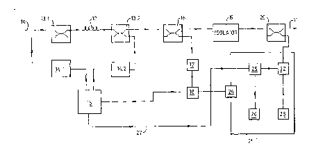
The photonic amplifier shown in Figure 1 has an
input port 10 which takes the form of an optical
fibre adapted for connection to a transmission
fibre, so that the amplifier can receive signals.
The amplifier also includes an output port 11 which
also takes the form of an optical fibre. The output
port 11 is also adapted for connection to a
transmission fibre in order that amplified signals
may be transmitted to the rest of the system, e.g.
to more amplifiers as illustrated in Figure 1. It
should be noted that the transmission fibres are not
shown in Figure 1 because the transmission fibres
are not part of the amplifier.
A fibre amplifier medium 12 interconnects the input
and output ports 10 and 11. This is a conventional
Er doped fibre and it requires pump radiation to
provide the power for amplification.
WO92/17~8 21 0 1 2 I 2 PCT/GB92/~24
The pump arrangements are constituted by
multiplexers 13.1 and 13.2 which are situated at
opposite ends of the fibre 12. The multiplexers
13.1 and 13.2 are connected to pumps 14.1 and 14.2
and these pumps take the form of semi-conductor
lasers which provide pump radiation at a wavelength
suitable for producing a population inversion in the
Er dopant in the fibre 12. The electrical drive to
the pumps 14.1 and 14.2 is provided and controlled
by a control unit 15. The provision of two pumps
constitutes a redundancy feature to prolong the life
of the amplifier should one of the pumps fail. The
control unit 15 selects one of the pumps, usually
14.1, to provide the pump radiation and it also
controls the intensity of the radiation in order to
control the gain in the amplifier. The control unit
preferably includes monitoring circuits to
ascertain the operational status of the amplifier,
e.g. to detect if both pumps 14.1 and 14.2 have
failed.
Three components are located between the multiplexer
13.2 and the output port 11. These are a splitter
16, an isolator 19, and a multiplexer 20. The
splitter 16 which provides 90% of the output of the
amplifier to the output port 11 and 10% to control
circuitry to be described below. The splitter 16 is
connected to the output port 11 via the isolator 19
and the multiplexer 20. The multiplexer 20 allows
both the output of the fibre and the distress
transmitter 21 (described below) to be provided to
the output port 11. In normal use the isolator 19
prevents the reflection of traffic signals back into
the amplifier 12. Such reflections are possible
and, if permitted, they would cause the amplifier to
WO92/17~8 210 ~ 2 12 PCT/GB92/~24
go into oscillation and generate unacceptable noise.
The isolator 19 reduces these reflections
sufficiently to prevent oscillation. In the
distress mode, the isolator 19 prevents distress
signals from the multiplexer 20 arriving at the
splitter 16.
An AGC includes an optical detector 17 which
receives 10% of the output of the fibre 12 from the
splitter 16. The detector 17 converts its optical
input into an electrical signal. However the
detector 17 is not wavelength sensitive and,
therefore, it converts not only traffic signals but
also noise into the same electrical signal. In
addition, the detector 17 will receive 10% of the
output of pump 14.1 and this optical input will also
be converted into the electric signal. However the
traffic signal is modulated with a control tone of
10 kHz and this tone is not present in the noise or
the pump radiation. Therefore the 10 kHz component
of the output of the detector 17 represents the
traffic signal. If the amplitude of the 10 kHz tone
falls to zero this indicates that the traffic signal
has vanished. The output of the detector 17 passes
to an electronic processor 18 which includes a band
pass filter for the 10 kHz tone. The pass band of
the filter should be wide enough to allow for drift
but it should be not so wide that unwanted noise
will pass the filter. Thus the output of band pass
filter represents the traffic signal, even though
pump radiation and other noise is detected by the
optical detector 17.
The level of the control tone is passed to the pump
control unit 15 which operates to maintain the level
W092/17~8 PCT/GB92/~K24
2104~1~
-- 10 -
of the control tone at a preset value. If the level
falls below the preset value the control unit 15
increases the power to the pump 14 whereby the
intensity of pump radiation is increased. This
increases the gain in the amplifier 12 which has the
effect of increasing the level of the control tone
to the preset value. Similarly, if the level of the
control tone exceeds a preset value, the control
unit 15 reduces the power to the pump and thereby
reduces the level of control tone into the preset
value. Thus the processor 18 and the control unit
15 constitute an AGC means which keeps the level of
control tone constant. Since the first transmission
unit provides a constant percentage of modulation,
the effect is that the traffic signals are
maintained at a preset level, and the circuit
operates as an AGC. Because it uses control tone,
the extraneous effects of noise on the AGC are
minimised.
The control unit 15 includes a limiter to prevent
excessive power being provided to the pumps, i.e. to
prevent the pumps being damaged by overload. The
power limiter comes into operation because the level
of control tone from the processor 18 has fallen
below a threshold level. For example, the level of
control tone may have fallen to zero because the
transmission fibre providing input to the input port
10 has been broken. The fact that the limiter has
come into operation is, therefore, an indication of
a serious malfunction upstream of the splitter 16.
Therefore the control unit 15 provides a warning
signal on the line 27 which is connected to a
distress transmitter which will now be described.
W092/17~8 2 1 0 4 2 12 PCT/GB92/~24
The distress transmitter 2l comprises an optical
transmitting element 22, which may be either a laser
or an LED, which when enabled produces optical
signals suitable for transmission through the
system. It may be convenient to use an LED which
produces a wide band optical signal, so that, if
drift occurs, some part of the signal will be within
the bandwidth of the system. This helps to ensure
that the distress signals are transmitted. If a
narrow bandwidth laser is used then it is important
to ensure that the wavelength produced by the laser
remains within the bandwidth of the system. In any
case, the transmitting element 22 produces a
distress optical signal which is transmitted onward
through the output port ll. The drive circuit of
the transmitting element 22 includes an electronic
oscillator 23 which produces a control tone of lO
kHz. Thus the optical signal produced by the
transmitting element 22 has the correct system
format and the control tone will be utilised by
subsequent amplifiers so that their AGC's remain
fully operational and transmit the signal. In
addition the presence of the control tone will
prevent subsequent amplifiers adopting the distress
configuration.
In addition to the control tone which is amplitude
modulated onto the output of the transmitting
element 22, the distress transmitter includes a
digital modulator 25 which digitally modulates the
distress signal with information which includes the
identity of the amplifier (stored in store 26). The
digltal modulatlon is repeated over and over again
as long as the distress condition lasts. The
repeated digital message comprises a package header
WO92/17~8 PCT/GB92/~24
210~
to identify the beginning of each repetition, and a
packet trailer for identifying the end of each
repetition. In between the header and trailer there
is located an identification word to identify the
amplifier which originates the distress message.
(If 8 bit words are used this provides 256 different
identification words. This would be sufficient to
provide a distinctive identification for every
amplifier in a chain about 20,000 km long. It is
unlikely that a chain of such length would ever be
needed.)
In addition to the identification, the digital
message may contain other codes to indicate the
nature of a fault. For example a special code could
be included to indicate that both pumps had failed.
It will be appreciated that the failure of both
pumps 14 would mean that there is no gain in the
amplifier 12, and hence the default condition would
develop. To provide this extra facility, a digital
modulator 25 is connected to the control unit 15 by
a line 27. This actuates the modulator 25 to
include a status word, defining the operative state
of the amplifier in any distress message. If the
amplifier itself is defective, the status word
indicates that the fault is located in the
amplifier. If the amplifier is operable, the status
word indicates that the fault occurs before the
input port 10, e.g. in the transmission fibre.
The power to operate the components (22, 23, 25 and
26) of the distress transmitter 21 is provided via
switching means 24. The switching means 24 is
operatively connected to processor 18. As long as
the level of the control tone is above a
W092/17~8 2 10 ~ 2 12 PCT/GB92/~K24
- 13 -
predetermined level, the switching means 24 is "off"
and the distress transmitter 21 is dlsabled because
it has no power. If the level of control tone falls
below the predetermined level, the switching means
24 is "on" and the distress transmitter 21 receives
power whereby it is enabled to transmit a distress
message as described above. So long as the level of
control tone remains low, power is supplied to pump
14.1 or 14.2 at a safe maximum level. This means
that the amplifier is retained in an operative
state, so that, when traffic or distress messages
are received, the processor 18 will again detect
control tone above the predetermined level. Thus
the switching means 24 will be returned to the "off"
configuration, the transmission of a distress
message will cease, and normal operation will be
resumed. Thus the processor 18 can switch from
"normal" to ''distressll operation, and from
"distress" operation to "normal" operation as
necessary. This ability will be utilised when the
amplifier is first switched on.
A submarine system may require a substantial number
of amplifiers, e.g. a long system will require 40 or
50 amplifiers. Using amplifiers as shown in Figure
1 lt is possible and convenient that all the
amplifiers have identical circuitry which clea: y
simplifies the production of the system. In fact
that only difference between the amplifiers is the
identify word which is stored in the storage
location 26. It is a simple matter to load the
identity when the amplifiers are being assembled
into the system.
WO92/17~ - PCT/GB92/~K~
~104~
- 14 -
Figure 2 shows a single optical linkage suitable for
telecommunications. The linkage comprises three
amplifiers 43, 44 and 45 each of which is as shown
in Figure 1. In fact all three amplifiers are
identical except for the identification stored in
location 26. Amplifier 43 is connected to amplifier
44 by an optical fibre 48 and amplifier 44 is
connected to amplifier 45 by an optical fibre 49.
Traffic is transmitted into the line by a laser 42
which is connected to amplifier 43 by a fibre 47.
Traffic initiated by the laser 42 is received at a
detector 46 which is connected to amplifier 45 by a
fibre 50. The laser 42 is located on one side of a
body of water whereas the detector 46 is located on
the other side of the body. Fibres 47, 48, 49 and
50 will usually be 80 - 100 km long so that the
complete link is about 300 - 400 km long. Thus,
even with only four amplifiers the link provides
transmission across a substantial body of water.
The chain could be extended to include 50 or more
amplifiers, in which case the link would provide
communication across a substantial ocean.
The laser 42 is connected by a suitable switching
centre, to the public switched network of its land
area. It receives telecommunications traffic on the
line 40 and this traffic is digitally modulated onto
the optical output of laser 42 so that the traffic
is transmitted across the link. The bias current to
laser 42 is modulated with a 10 kHz tone by the
oscillator 41, and, therefore, all the optical
signals in the link are modulated with this tone.
This tone is used to operate the AGC of each
amplifier 43, 44, and 45 and this feature has been
described above with reference to Figure 1. The
W092/17~ PCT/GB92/~24
2104212
-- 15 --
detector 46 converts the optical signals into
electrical signals which are provided onto a line 51
into a public switched network. Thus the link shown
in Figure 2 provides connection between the two
public switched networks.
As is usual in telecommunications practice, the
traffic in the line 51 is monitored by equipment 52,
which can distinguish between the presence and
absence of traffic on the line 51. The monitoring
equipment 52 would also detect the case where, owing
to a malfunction in line 40 the traffic is being
scrambled. This equipment operates because it can
recognise various synchronisation codes and various
parity checks which are included in the traffic.
The operation of the link shown in Figure 2 can now
be described.
Under normal operation traffic from the line 40 and
control tone from the oscillator 41 are both
transmitted along the whole line until detected by
the detector 46. The control tone from the
oscillator 41 actuates all the AGC's and thereby
keeps the line under satisfactory operation. The
traffic is validated by the monitoring equipment 52
and it is distributed to the public switched network
via the line 51 and no alarms are given. If a fault
occurs, e.g. if the fibre 48 breaks, then the
traffic disappears because it cannot be transmitted
through the break. The monitoring equipment 52 will
detect the absence of traffic and issue an alarm.
In addition, amplifier 44 will receive no control
tone from the oscillator 41 and, therefore, the
amplifier will adopt the distress configuration and
transmit a distress signal modulated with control
W092/17~ ~ 10 4 ~1~ PCT/GB92/~24
tone. Therefore amplifier 45 will receive control
tone and it will remain in the normal configuration
and transmit the distress signal via fibre 50 to the
detector 46. The optical signal will be modulated
with a digital distress signal from amplifier 44 but
this will not conform to the traffic specification
and, therefore, the alarm state will remain
operative. On examining the output from the
detector 46 the distress message from amplifier 44
will be recognised. If the distress packet
indicates pump (or other) failure in amplifier 44
the location of the problem has been diagnosed. If
the distress packet indicates that the amplifier 44
is still operable this is an indication that fibre
48 is broken. In either case the distress package
provides a valuable diagnostic aid in ascertaining
the location of the fault. It should be noted that
loss of traffic will initiate an alarm even if the
amplifiers do not include distress signalling. The
invention is concerned with indicating the location
of the fault.
It will be appreciated that the linkage shown in
Figure 2 is a one-way linkage because the AGC's of
the amplifiers are only capable of operating in one
direction. In order to provide two-way
communication between the terminals, it is necessary
to have a second line as shown in Figure 2 but
having its direction reversed. Because the
lndividual linkages are one-way, it is usual for a
telecommunications system to include an even number
of linkages so that half are used in one direction
and half in the other. This arrangement provides
equal traffic capacity in both directions.
WO92/17~ PCT/GB92/~24
2ln42i2
- 17 -
An amplifier cannot be placed directly in the ocean
because it needs to be protected. This protection
is achieved by placing the amplifiers in a
protective hull, and the hull usually contains a
plurality of amplifiers. Figure 3 constitutes a
diagramatic illustration of a repeater.
The repeater 66 usually consists of a cylindrical,
tubular hull which is about 0.5 - 2m long and about
200 - 500mm in diameter. To a large extent, the
maximum dimensions of a repeater are controlled by
the equipment carried on cable laying ships. As
shown in Figure 3, the repeater 66 is represented by
a rectangle which contains four amplifiers, each of
which is as described in Figure 1. More
specifically, the repeater 66 contains amplifiers
60A and 60B for transmission in one direction, and
amplifiers 60X and 60Y for transmission in the
opposite direction. The repeater 66 also contains
a power unit 61 which is connected to each of the
amplifiers to provide the electric power needed for
operation. The repeater 66 is connected at its two
ends to two submarine cables which contain a
plurality of transmission fibres, an electric
conductor and tensile wires to provide tensile
strength. The tensile wires are connected to the
hull of the repeater 66 so that, during laying, it
is supported on the tensile wires and the optical
and electrical components are not damaged. The
input ports lOA and lOB of amplifiers 60A and 60B
are connected to transmission fibres 62A and 62B in
one of the submarine cables, similarly the output
ports llX an~ o~ am~l~fiers 60X and 60Y are
connected to transmission fibres 62X and 62Y which
are contained in the same submarine cable as fibre
~10~ P~S~B ~ 2 i D 0~ 2~
il2 MAY 1993
- 18 -
62A and 62B. Similarly, at the other end of the
repeater, output fibres llA and llB are connected to
transmission fibres 63A and 63B and input fibres lOX
and lOY are connected to transmission fibres 63X and
63Y. These are all contained in the other submarine
cable to which the repeater 66 is attached. In
addition, the power unit 61 is attached to the
electrical conductors of the two submarine cables 64
and 65. Thus the power unit 61 receives its power
from the submarine cables and it receives power from
both sides. If one cable is cut, the amplifiers in
the repeater 66 still remain active because it still
receives power from the other side. It should be
noted that the transmission fibres and the
conductors all enter the repeater through watertight
bulk heads. T~hus the interior of the repeater 66
provides a satisfactory working environment for all
its amplifiers even when ~hè repeater is located on
the sea bed, possibly at depths of as much as 5 km.
Figure 3 shows four amplifiers in the repeater but
larger numbers, e.g. six or eight (i.e. three or
four in each direction) are more usual. It is
convenient for all the amplifiers in the same
repeater to have the same identification. When a
break in a fibre occurs between two adjacent
repeaters both repeaters will lose the tone control
with the result that distress signals will be sent
to both,ends of the line. Thus it is possible to
construct a submarine optical telecommunications
system having from 3 to 60 repeaters.
J
m ~atent~ ~ Sl~T~71J~