Note: Descriptions are shown in the official language in which they were submitted.
210433~
SPECIFICATION
CONTINUOUS SCRAP PREHEATING
JOHN A. VALLOMY
BACKGROUND OF THE INVENTION
This invention relates to the continuous
preheating of a principally metallic charge to form a
molten steel product. More particularly, it relates to
continuous preheating of organic compound contaminated
charge materials for continuous steelmaking in an
associated electric arc furnace (EAF) which reduces noxious
emissions generated by the furnace. Some regions of the
world have very strict emission standards. The present
invention addresses the problem steelmaking facilities have
in complying with these standards.
Continuous steelmaking is particularly
advantageous in those regions where there is a
concentration of production, or ready availability, of
scrap and/or direct reduced iron (DRI), and where electric
energy is both available and economical.
Non-metallics from metal-containing charge
materials often cause environmental problems, particularly
when burned at low temperatures, which results in
incomplete combustion. Under such conditions, the electric
arc steelmaking furnace produces noxious emissions,
including dioxins. These dioxins form in the furnace or in
dust collection ducts from combustion of plastics from
pipes and cars, synthetic fibers, paints, cutting oils from
turnings, and the like. Dioxins form at temperatures
between about 300 and 520~C, with the most favourable
temperature for forming such compounds being about 420 to
470~C. Dioxins generally form in the presence of chlorine.
The reaction is catalyzed by the presence of copper or
other catalyst. In general, the temperature required for
dioxin creation is from about 320 to 520~C. Dioxins form
readily when combustion takes place at low temperatures.
The use of chlorinated compounds in iron and steel
processes and recycled scrap material contaminated with
2~337
-- 2
cutting oils and plastics containing chlorine, such as PVC,
provides all the factors required for the formation of the
chlorinated aromatic compounds polychlorinated dibenzo
dioxins (PCDD) and polychlorinated dibenzo furans (PCDF).
Such harmful compounds are not produced during
continuous scrap preheating and feeding in the present
process, because the organic matter in the scrap charge is
combusted at high temperatures before it reaches the
furnace, and the atmosphere within the preheater is
carefully controlled. The incineration chamber following
the preheater provides sufficiently high temperature,
sufficient turbulence, and an excess of oxygen which
results in dioxins and precursors being destroyed. If the
destruction of dioxins at this stage is complete, formation
later on in the system is not possible.
Historically, the operation of an electric arc
steelmaking furnace has been an intermittent operation,
wherein the sequence followed is: charging of steel scrap
and/or direct reduced iron, pig iron, slag formers and
alloying elements; ignition or establishment of an electric
arc between the electrodes in the furnace to create melting
conditions for melting the charge and forming a molten
metal bath covered by a molten slag; refining for a period
of time during which the molten metal portion of the bath
is refined to form steel having a desired composition and
quality; and periodically raising the electrodes to remove
them from contact with the bath and interference with the
tapping procedure; and then tapping the molten metal. In
addition, slag can be removed by a deslagging, or slag-off,
operation as required.
The present invention is particularly well suited
for use in the continuous steelmaking process described in
my US Patents 4,543,124 and 4,609,400.
21~4337
-- 3
SUMMARY OF THE INVENTION
The present invention is a method and apparatus
for continuously preheating charge materials for the
continuous refining of steel in an associated steelmaking
furnace. Iron-bearing scrap in shredded, sheared or
granular form, direct reduced iron, commercial scrap, or a
mixture thereof, generally containing organic materials or
compounds, form the principal part of the charge, which is
passed continuously on a conveyor through a dynamic seal at
the material entry end of a preheating chamber then through
a gas exhaustion section, a heating section and a feed
discharge section of the chamber. Heat is provided by
chemical and sensible heat from the off-gas from a
steelmaking furnace, preferably an electric arc furnace,
provided sufficient oxygen is injected into the furnace to
create sufficient carbon monoxide (CO) in the furnace
off-gas to achieve the desired preheating temperature of
the scrap from combustion of the hot CO. Oxygen is
provided by injection of combustion air into the scrap
preheater, as required. If insufficient oxygen is injected
into the furnace to provide the necessary heat for
preheating the scrap to the desired temperature, additional
heat is provided from available fuel through burners in the
preheater hood whereby the heat obtained from the carbon
monoxide from the furnace is augmented to create sufficient
combustion gas to achieve the desired scrap preheating
temperature.
Air may be used to cool the conveyor during
preheating to preheat the air for injection into the
preheater, and to cool the portion of the conveyor in
contact with the charge. The process utilizes the carbon
monoxide generated from oxygen injection into the molten
metal bath within the associated electric arc steelmaking
furnace, or other available fuel, or a combination thereof,
as the source of heat for scrap preheating in the
preheating chamber.
21~433~
-- 4
The preheating chamber has an associated
secondary gas-treating chamber at the material entry end to
ensure thermal incineration of any residual combustible
matter. The organic matter in the scrap charge is
combusted at high temperatures and the atmosphere within
the preheater is carefully controlled, preventing or
limiting the formation of noxious emissions, such as
dioxins or furans, among others, in the preheater. The
products of combustion and associated off-gases are removed
in the gas transition section. The atmosphere in the
preheating chamber is progressively changed from an
oxidizing atmosphere at the gas transition section to a
reducing atmosphere at the mixture discharge section. By
providing excess oxygen of 3-4% with 2 seconds residence
time at 900 to 1100~C, in the associated gas treating
chamber, any furans and dioxins are incinerated in the gas
removed from the preheater prior to the continuous
discharge of the mixture into a steelmaking furnace.
The apparatus of the invention includes conveyor
means, having a charge material entry end and a material
discharge end, support means for said conveyor means, a
cover over a portion of said conveyor means forming a
heating chamber with said support means, said heating
chamber comprising sequentially a gas transition zone, a
heating zone, and a feed mixture discharge zone, gas seal
means at the material entry end of said conveyor means to
the heating chamber, means for connecting and sealing the
heating chamber to a steelmaking furnace, means for
introducing heat to the interior of said heating chamber,
means for removing off-gases at the material entry end of
said heating chamber, and means for heating removed
off-gases to a high temperature and for holding such
temperature for a predetermined time.
21~337
-- 5
OBJECTS OF THE INVENTION
It is the principal object of this invention to
provide a method and apparatus for the continuous
preheating of charge materials to an electric steelmaking
furnace.
It is also an object of this invention to provide
a method and apparatus which will preheat a desired
quantity of scrap at a controlled rate, while complying
with local environmental regulations.
It is also an object of this invention to provide
a method and apparatus for reducing noxious emissions from
an associated EAF during continuous preheating of charge
materials.
It is another object of this invention to provide
an efficient continuous charge preheater which will utilize
off-gases from the associated steelmaking furnace to
provide a portion of the heat required for preheating.
It is another object of this invention to provide
apparatus for preheating a furnace charge, which will
simultaneously reduce or eliminate noxious gases.
BRIEF DESCRIPTION OF THE DRAWINGS
The foregoing and other objects will become more
readily apparent by reference to the following detailed
description and the appended drawings, in which:
Figure 1 is an elevational cross section of the
invented apparatus, including the furnace connection.
Figure 2 is a top view of the apparatus for
preheating charge materials in a continuous steelmaking
operation, in accordance with the invention.
Figure 3 is a vertical cross section of the
apparatus of Figure 1 as utilized in the present invention.
Figure 4 is a schematic representation of the
entire apparatus for preheating charge materials and
preventing emission of noxious gases in a continuous
steelmaking operation, in accordance with the invention.
21 04337
-- 6
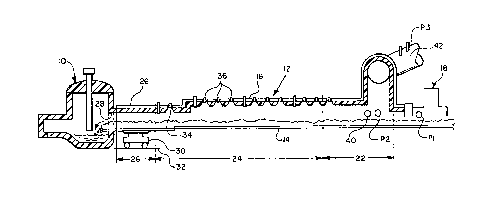
DETAILED DESCRIPTION
Referring now to the drawings, an electric arc
steelmaking furnace 10 has an associated elongated
preheating chamber 12, preferably a vibrating channel, for
introducing charge materials, both metallics and
non-metallics, into the furnace. The furnace 10, although
shown as a three-phase electric arc furnace, alternatively
- can be a direct current electric furnace, a plasma- furnace
or an induction furnace. The chamber 12 has an elongated
support 14 covered by a mating elongated hood 16,
preferably refractory-lined, and generally in accordance
with my US Patent 4, 609, 400
The heating chamber 12 has a dynamic seal 18
at the charge material entry end, and from the charge
material entry end the heating chamber includes
sequentially a gas transition section or zone 22, one or
more heating sections or zones 24, and a material discharge
section 26. Furnace 10 has an off-gas exit orifice 28.
The discharge section of the chamber is mounted on a
connecting car 30 for telescoping axial movement into
engagement with the furnace opening 18 which effectively
seals the stationary chamber 12 to the furnace 10, which
may be tiltable. The connecting car feeds the scrap from
the heater to the furnace at the proper location within the
furnace. The connecting car is advantageously mounted on
a track 32.
Furnace off-gas from furnace 10, the temperature
of which is usually about 1300~C, enters the refractory
lined scrap heating chamber 12 through material discharge
opening 28. The furnace off-gas provides heat to the
charge in the scrap heater chamber in two manners, by both
the sensible and chemical heat contained in the furnace
off-gas. Near the material discharge end of the heating
chamber 12, a safety burner 34 is mounted for igniting
combustible gases which have not reached the temperature of
combustion. The safety burner is used only when the
2i~433~
-- 7 --
temperature within the heating zone 24 is below the flash
point temperature of the furnace off-gas.
Heating sections 24, 24A, 24B, etc, are provided
with air injectors 36 in the respective hood 16 of each
section. Any desired number of heating sections may be
employed, and they may be of the same or varying lengths.
The air injectors direct air or oxygen enriched air for gas
combustion downwardly against the scrap beneath them. As
shown in Figure 2, multiple air injectors or ports A, B, C,
D, etc., may be provided within the hood of each heating
section for good control of the combustion air injection.
Air injectors are used if there is sufficient carbon
monoxide in the furnace gas produced to preheat the scrap
to the desired temperature. Alternatively, these hoods may
be provided with burners in addition to air injectors. The
steelmaking furnace can operate without oxygen injection,
in which case little or no CO is produced to use as fuel in
the scrap heater. In such case, burners utilizing
available fuel are utilized instead of air injectors to
produce the desired scrap heating in the heating zone 24.
Combustion air distribution is controlled to
obtain even combustion throughout the preheating chamber.
An oxygen sensor 40 which is located in the gas transition
section 22 of the elongated scrap preheating chamber 12
determines the amount of oxygen in the off-gas about to
exit the chamber 12. This sensor 40 controls the
introduction of air through injectors 36 to allow the
operation to progressively change the atmosphere within the
scrap heating chamber from reducing at the mixture
discharge end to oxidizing in the gas transition zone; that
is, first reducing in character to avoid re-oxidation of
the feed material, then the oxygen in the gas mixture is
progressively increased to 3 to 5~ excess oxygen, thus
assuring that combustion of all combustible matter is
complete within the scrap heating chamber. Since the air
is injected evenly throughout the whole length of the
21~433~
-- 8
heating zone 24 the atmosphere is changed gradually and
evenly along the entire length of the heating chamber, with
no dramatic change in any portion, thus maintaining even
distribution of combustion to preheat the scrap.
Non-metallic combustible matter in the charge is burned
off, and the charge is heated to at least 500~C, and to a
maximum temperature of approximately 800 to 1000~C.
Oxygen sensor 40, which is preferably a multiple
gas analyzer, regulates the adjustment of combustion
air-injectors and/or burners and the rate of combustion in
the chamber 12. Near the oxy-fuel burner 68, the heating
gas composition includes about 3 to 5% excess oxygen. A
small amount of air enters the gas transition zone 22
through the dynamic seal 18. This is controlled by
adjustment of pressure Pl in the dynamic seal 18, pressure
P2 in the gas transition zone 22, and pressure P3 in the
secondary gas treating chamber. Flow of gas through the
secondary gas treating chamber and pressure in the system
are controlled by damper 70. When the flue gas reaches the
gas transition zone, its composition includes a minimum of
3~ excess oxygen.
The scrap charge enters the preheater chamber 12
on a conveyor through dynamic gas seal 18. Preheater
off-gas handling equipment is connected to the chamber 12
near and above gas seal 18. The hot off-gas treating
system includes an elongated refractory-lined secondary
combustion chamber or thermal incinerator 42, a gas
passageway connecting the incinerator to the chamber 12, a
waste heat boiler 50 or gas quenching unit, a fan or blower
52, a bag house 54, and associated piping. Pipe 56, which
connects gas pipe 58 between the boiler and bag house, is
also connected to the ventilating system 60 of the building
in which the steelmaking furnace is located.
An oxygen sensor 66 is provided within the
thermal incinerator to determine the fuel-oxygen ratio
required by burner 68 for adding additional heat or oxygen
2 1 ~) ~ 3 3 r~
g
to the off-gas entering the thermal incinerator. Burner 68
is an oxy-fuel burner in the gas transition section to
maintain both the temperature of the gas and the oxygen
level within the pre-established limits.
Referring now to Figures 2 and 3, which depict
the preferred embodiment of the charge preheater apparatus,
vibrating channel 44 acts as the conveyor. The dynamic
seal 18 at the material entry end of the conveyor is formed
by a chamber using air to prevent escape of flue gases from
the scrap heating chamber to the atmosphere at that
location by admitting a certain controlled low volume of
alr .
The term "scrap" as used throughout this
specification and claims means charge material for
continuous melting, including ferrous scrap, pig iron and
direct reduced iron in pellet or briquette form. Scrap may
be separated by grades of purity, shredded or sheared to
suitable size, if necessary for continuous feeding into the
furnace, and stored by grade until required for feeding.
Scrap defined as "commercial grade" by the Iron and Steel
Scrap Institute (ISSI) is preferred. Pig iron is
granulated or broken into appropriate size for feed stock.
Charge material is selected from the stored scrap
material and other feed stock, weighed and fed onto the
conveyor. The charge material is preheated in chamber 12,
by passing furnace off-gas through and over it,
counter-current to the flow of the charge into the furnace.
The steelmaking furnace operates continuously at
full power for an extended period of time up to
approximately six or seven days during which time only
minor lining repairs are made to the furnace. Slag in the
furnace is kept in the foaming condition during all phases
of the process, including the tapping phase, and full power
is maintained to the furnace during tapping. Foaming slag
is caused mainly by the liberation of C0 within the bath
and the slag. The carbon necessary for reaction with the
2104337
-- 10 --
oxygen in the charge is injected into the slag or
slag-metal interface of the bath in the form of powdered
carbon or coke through one or more underbath tuyeres. If
there is insufficient oxygen present in the bath, oxygen
can also be injected through underbath tuyeres to effect
the necessary reaction with carbon to promote a foaming
slag. Carbon and/or oxygen may be injected into the bath
at any time. The carbon injection and the oxygen injection
promote the formation of carbon monoxide. About 70 to 75%
of the C0 produced in the furnace passes out of the furnace
into the scrap preheating chamber as fuel in the furnace
off-gas.
In order to assure that all combustion of off-gas
is completed upon its exit from the preheating chamber, it
is necessary to have a residence time of 2.0 seconds at a
temperature of 900 - 1100~C in the secondary combustion
chamber. By providing excess oxygen of 3-5% in the
incineration chamber with at least 2 seconds gas residence
time at 900 to 1100~C, harmful emission levels of dioxins
are incinerated.
Given the presence of the necessary chemical
constituents, dioxins and furans may form in the presence
of catalysts, such as copper or iron, when off-gas is
cooled after incineration. To prevent such formation, it
is important that the gases pass through the 300 - 500~C
range quickly, i.e. in the waste heat boiler or gas
quencher, to lower the gas temperature rapidly below this
range.
To complete the system and ensure that the vast
majority of emissions are treated, a building ventilation
system 60 is provided to collect secondary gas emissions
from the furnace and other gaseous and particulate matter
from the building. Gases from the ventilation system pass
through pipe 58 to pipe 56 where they are mixed with the
waste heat boiler flue gases, then enter bag house 54
210~3~7
through blower 52, for cleaning prior to discharge of the
cleaned cooled gases to the atmosphere.
In operation, iron-bearing material and other
feed materials are mixed as desired, the mixture is
continuously passed through a dynamic seal into an
elongated heating chamber having sequentially a feed
mixture entry end, a gas transition section, a heating
section and a feed mixture discharge section. An
associated electric arc steelmaking furnace which is fed by
the mixture of feed materials generates carbon monoxide
off-gas, which is removed into the heating chamber and
combusted therein. The off-gas is generated by reaction of
carbon in the bath (from feed materials and/or carbon
injected into the bath) with oxygen injected into the bath.
The heat of combustion and the sensible heat of the furnace
off-gas combined heat the chamber and the mixture therein
by the hot off-gases passing through and over the mixture
within the chamber. A progressively changing atmosphere is
maintained within the heating chamber, from reducing at the
mixture discharge end to oxidizing in the gas transition
section. The products of combustion and associated
off-gases are removed from the gas transition section of
the chamber into an associated refractory lined secondary
gas-treating chamber communicating with the gas transition
section. The temperature of the removed products of
combustion and associated off-gases is maintained at a
temperature in the range of 900 to 1100~C for a period of
at least 2 seconds in the secondary gas-treating chamber,
then cooled and discharged. The heated feed mixture is
discharged continuously and directly into the associated
steelmaking furnace.
When using the CO from the furnace as fuel to
preheat the scrap, an excess of combustion air is
introduced to the scrap preheating chamber in relation to
the CO. After a few seconds, the air supply is controlled
to maintain the desired excess of oxygen in the gas
2104337
- 12 -
transition section 22. It is desirable to maintain a
sufficient velocity of air to reach the top of the scrap on
the conveyor.
SUMMARY OF THE A~l~V~MENT OF THE
OBJECTS OF THE INVENTION
From the foregoing, it is clear that I have
invented a method and apparatus for the continuous
preheating of charge materials for use in conjunction with
the operation of an electric steelmaking furnace, which
allows continuous preheating of scrap materials and
continuous or semi-continuous charging, while avoiding the
production and emission of noxious gases, while maintaining
good control over both quality and product chemistry.