Language selection

Search

Patent 2104552 Summary

Third-party information liability

Some of the information on this Web page has been provided by external sources. The Government of Canada is not responsible for the accuracy, reliability or currency of the information supplied by external sources. Users wishing to rely upon this information should consult directly with the source of the information. Content provided by external sources is not subject to official languages, privacy and accessibility requirements.

Claims and Abstract availability

Any discrepancies in the text and image of the Claims and Abstract are due to differing posting times. Text of the Claims and Abstract are posted:

  • At the time the application is open to public inspection;
  • At the time of issue of the patent (grant).
(12) Patent: (11) CA 2104552
(54) English Title: COLLAPSING FRAME FOR MOVING TUBES OF PLASTIC MATERIAL
(54) French Title: CADRE A EFFONDREMENT POUR TUBES EN MOUVEMENT CONTENANT DES SUBSTANCES EN PLASTIQUE
Status: Expired and beyond the Period of Reversal
Bibliographic Data
(51) International Patent Classification (IPC):
  • B29C 53/20 (2006.01)
  • B29C 53/10 (2006.01)
(72) Inventors :
  • PLANETA, MIREK (Canada)
(73) Owners :
  • MIREK PLANETA
(71) Applicants :
  • MIREK PLANETA (Canada)
(74) Agent: GOWLING WLG (CANADA) LLP
(74) Associate agent:
(45) Issued: 2000-02-29
(22) Filed Date: 1993-08-20
(41) Open to Public Inspection: 1994-03-17
Examination requested: 1997-02-24
Availability of licence: N/A
Dedicated to the Public: N/A
(25) Language of filing: English

Patent Cooperation Treaty (PCT): No

(30) Application Priority Data:
Application No. Country/Territory Date
07/945,781 (United States of America) 1992-09-16

Abstracts

English Abstract


A collapsing frame for collapsing a moving tube of
plastic material from a circular cross section to a
flattened form has a pair of frame members positionable on
diametrically opposite sides of the tube to converge towards
each other in the direction of movement of the tube so as to
collapse the tube by engagement of the tube therewith. Each
frame member has mounted thereon for engagement by the tube
a series of longitudinally spaced roller assemblies mounted
for free rotation about axes substantially transverse to the
direction of movement of the tube. Each roller assembly
comprises at least one rotatable roller having a peripheral
surface oriented to tend to move the tube at an outwardly
inclined angle to the direction of movement of the tube.


Claims

Note: Claims are shown in the official language in which they were submitted.

I CLAIM:
1. A collapsing frame for collapsing a moving tube of
plastic material from a circular cross section to a
flattened form, said frame comprising;
a pair of frame members positionable on diametrically
opposite sides of the tube to converge towards each other in
the direction of movement of the tube so as to collapse the
tube by engagement of the tube therewith;
each frame member having mounted thereon for engagement
by the tube a series of longitudinally spaced roller
assemblies mounted for free rotation about axes
substantially transverse to the direction of movement of the
tube;
each roller assembly comprising a series of
independently rotatable rollers each having a peripheral
surface oriented to tend to move the tube at an outwardly
inclined angle to the direction of movement of the tube, and
each roller having a diameter in the range 12.5mm to 25mm
and a length in the range of 12mm to 5cm.
2. A collapsing frame according to claim 1, wherein each
roller has a helically contoured peripheral surface to tend
to move the tube at an outwardly inclined angle to the
direction of movement of the tube.
3. A collapsing frame according to claim 1 wherein said
rollers are mounted on axles which extend in a direction
-7-

substantially transverse and rearwardly inclined to the direction
of movement of the tube to tend to move the tube at an
outwardly inclined angle to the direction of movement of the
tube.
4. A collapsing frame according to claim 1 comprising
central rollers in a medial area mounted on axles which extend
perpendicularly to the direction of movement of the tube, and
side rollers on each side of the central rollers, said side rollers
being mounted on axles which extend in opposed directions
substantially transverse and rearwardly inclined to the direction
of movement of the tube to tend to move the tube at an
outwardly inclined angle to the direction of movement of the
tube.
8

Description

Note: Descriptions are shown in the official language in which they were submitted.


~~.d~55~
COLLAPSING FRAME FOR MOVING TUBES OF PLASTIC MATERIAL
This invention relates to collapsing frames for moving
tubes of plastic material.
When thin plastic film is extruded in the form of a
tube, which is then frequently expanded to produce thinner
tube by feeding air under pressure to the interior of the
tube, the tube is subsequently collapsed to a flattened form
to enable it to be more readily handled, for example for
feeding the tube to a storage roll or bag-making machine.
The tube is usually collapsed from a circular
cross-section to a flattened form by feeding the tube
through a collapsing frame comprising two frame members
which are inclined symmetrically and oppositely towards the
tube in the direction of travel thereof to provide a
gradually narrowing passage between the frame members from
which the collapsing tube is feed to the nip of a pair of
rollers which complete the flattening. The collapsing takes
place against the force exserted by the internal air
pressure within the tube which presses the tube against the
frame members of the collapsing frame.
U.S. Patent No. 4,533,309 (Planeta) Issued August 6,
1985, teaches a collapsing frame having mounted thereon for
engagement with the tube a plurality of parallel roller
assemblies mounted for free rotation about respective
parallel axes that are perpendicular to the direction of
tube movement, each roller assembly comprising a plurality
of independently rotatable rollers, each providing a surface

2104552
having a low coefficent of friction with the material of the
tube, mounted side-by-side with one another to provide a
substantially continuous surface of engagement with the
tube, said independently rotatable rollers constituting
means effective to permit different parts of the tube in
contact with the same roller assembly to have different
speeds in the direction of movement of the tube.
Although the collapsing frame described in the above
patent was a substantial improvement in prior collapsing
frames for minimizing wrinkling of the tube during
flattening, some tubes collapsed by the frames such as those
described in the above patent are not as sufficiently
wrinkle free as is desired.
It is therefore an object of the present invention to
provide an improved collapsing frame which still further
minimizes wrinkling when a tube of thin plastic material is
collapsed.
According to the present invention, each frame member
has mounted thereon for engagement by the tube a series of
longitudinally spaced roller assemblies mounted for free
rotation about axes substantially transverse to the
direction of movement of the tube, each roller assembly
comprising at least one rotatable roller having a peripheral
surface oriented to move the tube at an outwardly inclined
angle to the direction of movement of the tube.
The rollers may have a helically contoured surface to
tend to move the tube at the outwardly inclined angle.
- 2 -

.~ ~I~455~
Alternatively or additionally, the rollers may be mounted on
an axle which extends in a direction substantially
transverse and rearwardly inclined to the direction of
movement of the tube.
Embodiments of the invention will now be described, by
way of example, with reference to the accompanying drawings,
of which:
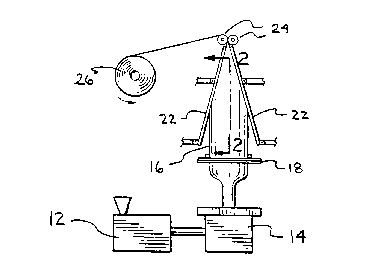
Figure 1 is a diagrammatic side view of an installation
for manufacturing thin plastic film in a tubular form and
showing use of a collapsing frame;
Figure 2 is a front view, partially broken away, of a
collapsing frame member in accordance with one embodiment of
the invention (for clarity the majority of the roller
assemblies have been indicated by chain-dotted lines);
Figure 3 is a front view on an enlarged scale of the
central portion of a roller assembly indicated by the circle
3 in Fig.2;
Figure 4 is a similar view of a roller assembly in
accordance with a further embodiment of the invention; and
2U Figure 5 is a similar view (on a smaller scale) of a
still further embodiment.
Referring to the drawings, Figure 1 shows an
installation for manufacturing thin plastic film in tubular
form. Plastic material, usually in pellet form, is fed to
an extruder 12 from which molten plastic material is
extruded and fed to a die assembly 14 which has a circular
annular oriface (not shown) in which the plastic material
emerges in the form of an outwardly moving tube 16 of
- 3 -

._ 21~4.~5~
circular cross section. The tube 16 is cooled by air from a
surrounding air ring 18 and at the same time air is fed to
the interior of the tube 16 at a pressure sufficiently high
to cause the tube to increase in diameter and become
thinner. The maximum diameter of the expanded tube 16 is
determined by the internal air pressure and also by a sizing
frame surrounding the tube.
The molten plastic forming the upwardly moving tube
solidifies, and the tube is then progressively collapsed to
the required flattened form by a collapsing frame comprising
a pair of flat rectangular frame members 22 mounted on
diametrically opposite sides of the tube 16 so that they
converge towards each other in the direction of movement of
the tube 16. The frame members 22 are contacted by the
moving tube 16 which is progressively flattened thereby and
fed between two driven rollers 24 which complete the
collapsing and flattening of the tube 16. The collapsed
flattened tube 16 is then wound onto a storage roller 26.
Figure 2 shows a collapsing frame member 22 in
2U accordance with one embodiment of the invention. The frame
member 22 has a rectangular frame 30 having mounted thereon
a series of longitudinally spaced roller assemblies 32
mounted for free rotation about axes perpendicular to the
direction of the movement of the tube 16.
Each roller assembly 32 has a series of independently
rotatable rollers 34a, 34b, rotating on a common axle 35
extending perpendicularly to the direction of the movement
of the tube 16. As shown more clearly in Figs. 3, the
- 4 -

zs~~.~~z
rollers 34a on the left hand side of the longitudinal centre
line 36 of the frame member 22 have a raised helically
contoured peripheral surface 38 which tends to move the tube
16 at an outwardly inclined angle to the longitudinal centre
line 36 as the tube 16 moves upwardly over the frame members
22.
Similarly, the rollers 34b on the right hand side of
the longitudinal centre line 36 have a raised helically
contoured peripheral surface 40 which tends to move the tube
16 at an outwardly inclined angle to the longitudinal centre
line 36 as the tube 16 moves upwardly over the frame members
22.
It has been found that the above arrangement reduces
the tendency of the tube 16 to becomes wrinkled as it is
flattened by the collapsing frame member 22.
Figure 4 shows an alternative arrangement. Each roller
assembly 42 comprises rollers 44a, 44b with cylindrical
peripheral surfaces. The rollers 44a on the left hand side
of the longitudinal centre line 36 are mounted on axles 46
which are substantially transverse to but rearwardly
inclined to the direction of travel of the tube 16.
Similarily, the rollers 44b on the right hand side of the
longitudinal centre line 36 are mounted on axles 48 which
are substantially transverse but rearwardly inclined to the
direction of movement of the tube 16. This arrangement also
reduces the tendency of the tube 16 to become wrinkled as it
is flattened by the collapsing frame member 22.
Figure 5 shows another alternative arrangement. Each
- 5 -

~~c~~~~z
roller assembly 52 comprises rollers 54a, 54b, 54c with
cylindrical peripheral surfaces. The central rollers 54a in
the medial area, i.e, immediately adjacent and on both sides
of the longitudinal centre line 36, are mounted on central
axles 56 which extend perpendicularly to the direction of
movement of the tube 16. The left hand side rollers 54a are
mounted on axle 58 which extend from the left hand ends of
the central axles 56 in a rearwardly inclined direction, and
the right hand rollers 54c are mounted on axles 60 which
extend from the right hand ends of the central axles 56 in a
rearwardly inclined direction. This arrangement also
reduces the tendency of the tube 16 to become wrinkled as it
is flattened by the collapsing frames members 22.
The rollers 44a, 44b of Fig.4 and the rollers 54a, 54b
54c of Fig.5 may be provided with raised helically contoured
peripheral surfaces as in Fig.l if desired.
Preferably, the rollers are of diameter in the range
12.5mm to 25mm and are of length in the range of l2mm to 5cm.
Other embodiments of the invention will be readily
apparent to a person skilled in the art, the scope of the
invention being defined by the appended claims.
- 6 -

Representative Drawing
A single figure which represents the drawing illustrating the invention.
Administrative Status

2024-08-01:As part of the Next Generation Patents (NGP) transition, the Canadian Patents Database (CPD) now contains a more detailed Event History, which replicates the Event Log of our new back-office solution.

Please note that "Inactive:" events refers to events no longer in use in our new back-office solution.

For a clearer understanding of the status of the application/patent presented on this page, the site Disclaimer , as well as the definitions for Patent , Event History , Maintenance Fee  and Payment History  should be consulted.

Event History

Description Date
Inactive: IPC expired 2019-01-01
Time Limit for Reversal Expired 2009-08-20
Letter Sent 2008-08-20
Inactive: IPC from MCD 2006-03-11
Grant by Issuance 2000-02-29
Inactive: Cover page published 2000-02-28
Inactive: Final fee received 1999-11-30
Pre-grant 1999-11-30
Notice of Allowance is Issued 1999-06-10
Letter Sent 1999-06-10
Notice of Allowance is Issued 1999-06-10
Inactive: Status info is complete as of Log entry date 1999-06-08
Inactive: Application prosecuted on TS as of Log entry date 1999-06-08
Inactive: Approved for allowance (AFA) 1999-05-28
All Requirements for Examination Determined Compliant 1997-02-24
Request for Examination Requirements Determined Compliant 1997-02-24
Application Published (Open to Public Inspection) 1994-03-17

Abandonment History

There is no abandonment history.

Maintenance Fee

The last payment was received on 1999-07-21

Note : If the full payment has not been received on or before the date indicated, a further fee may be required which may be one of the following

  • the reinstatement fee;
  • the late payment fee; or
  • additional fee to reverse deemed expiry.

Patent fees are adjusted on the 1st of January every year. The amounts above are the current amounts if received by December 31 of the current year.
Please refer to the CIPO Patent Fees web page to see all current fee amounts.

Fee History

Fee Type Anniversary Year Due Date Paid Date
MF (application, 4th anniv.) - standard 04 1997-08-20 1997-07-03
MF (application, 5th anniv.) - standard 05 1998-08-20 1998-06-26
MF (application, 6th anniv.) - standard 06 1999-08-20 1999-07-21
Final fee - standard 1999-11-30
MF (patent, 7th anniv.) - standard 2000-08-21 2000-07-18
MF (patent, 8th anniv.) - standard 2001-08-20 2001-07-05
MF (patent, 9th anniv.) - standard 2002-08-20 2002-06-06
MF (patent, 10th anniv.) - standard 2003-08-20 2003-06-25
MF (patent, 11th anniv.) - standard 2004-08-20 2004-07-27
MF (patent, 12th anniv.) - standard 2005-08-22 2005-07-08
MF (patent, 13th anniv.) - standard 2006-08-21 2006-08-17
MF (patent, 14th anniv.) - standard 2007-08-20 2007-07-27
Owners on Record

Note: Records showing the ownership history in alphabetical order.

Current Owners on Record
MIREK PLANETA
Past Owners on Record
None
Past Owners that do not appear in the "Owners on Record" listing will appear in other documentation within the application.
Documents

To view selected files, please enter reCAPTCHA code :


To view images, click a link in the Document Description column. To download the documents, select one or more checkboxes in the first column and then click the "Download Selected in PDF format (Zip Archive)" or the "Download Selected as Single PDF" button.

List of published and non-published patent-specific documents on the CPD .

If you have any difficulty accessing content, you can call the Client Service Centre at 1-866-997-1936 or send them an e-mail at CIPO Client Service Centre.


Document
Description 
Date
(yyyy-mm-dd) 
Number of pages   Size of Image (KB) 
Representative drawing 1998-08-16 1 4
Representative drawing 2000-01-31 1 6
Claims 1994-04-17 2 46
Drawings 1994-04-17 2 56
Description 1994-04-17 6 226
Abstract 1994-04-17 1 22
Description 1999-05-18 6 227
Claims 1999-05-18 2 53
Commissioner's Notice - Application Found Allowable 1999-06-09 1 165
Maintenance Fee Notice 2008-09-30 1 172
Maintenance Fee Notice 2008-09-30 1 171
Fees 2003-06-24 1 28
Correspondence 1999-11-29 1 39
Fees 1997-07-02 1 48
Fees 2001-07-04 1 31
Fees 2002-06-05 1 34
Fees 1998-06-25 1 45
Fees 1999-07-20 1 40
Fees 2000-07-17 1 40
Fees 2004-07-26 1 33
Fees 2005-07-07 1 30
Fees 2006-08-16 1 31
Fees 2007-07-26 1 32
Fees 1996-07-31 1 48
Fees 1995-05-22 1 45
Prosecution correspondence 1997-02-23 1 43
Examiner Requisition 1999-03-17 2 47
Prosecution correspondence 1999-04-18 2 83
Prosecution correspondence 1998-10-07 2 101