Language selection

Search

Patent 2104553 Summary

Third-party information liability

Some of the information on this Web page has been provided by external sources. The Government of Canada is not responsible for the accuracy, reliability or currency of the information supplied by external sources. Users wishing to rely upon this information should consult directly with the source of the information. Content provided by external sources is not subject to official languages, privacy and accessibility requirements.

Claims and Abstract availability

Any discrepancies in the text and image of the Claims and Abstract are due to differing posting times. Text of the Claims and Abstract are posted:

  • At the time the application is open to public inspection;
  • At the time of issue of the patent (grant).
(12) Patent Application: (11) CA 2104553
(54) English Title: CLAMPING AND COUPLING MEANS
(54) French Title: METHODE DE BRIDAGE ET DE COUPLAGE
Status: Deemed Abandoned and Beyond the Period of Reinstatement - Pending Response to Notice of Disregarded Communication
Bibliographic Data
(51) International Patent Classification (IPC):
  • F16L 55/172 (2006.01)
  • F16L 21/06 (2006.01)
  • F16L 33/04 (2006.01)
(72) Inventors :
  • KRAUSZ, ELIEZER (Israel)
(73) Owners :
  • ELIEZER KRAUSZ
(71) Applicants :
(74) Agent: AVENTUM IP LAW LLP
(74) Associate agent:
(45) Issued:
(22) Filed Date: 1993-08-20
(41) Open to Public Inspection: 1994-02-27
Availability of licence: N/A
Dedicated to the Public: N/A
(25) Language of filing: English

Patent Cooperation Treaty (PCT): No

(30) Application Priority Data:
Application No. Country/Territory Date
102,960 (Israel) 1992-08-26

Abstracts

English Abstract


ABSTRACT
The invention relates to clamping, coupling and
connecting means to be used, and with pipes of different
materials, and also with hose like fluid conduits of plastics,
rubber or like materials. The clamp relates to the kind known
as clamp couplings, and are used also, but not exclusively, for
the repair of metal or synthetic material conduits which have
sprung a leak, especially in cases where the immediate and speedy
repair is mandatory in order to avoid loss of the respective
fluid, be it liquid or gaseous, and the possible environmental
damage which might be a consequence of such leak. In its
broadest aspects, such means comprise a relatively wide metal
band provided with a tightening arrangement, the band being
designed to be placed around a pipe or hose, such that, by means
of the unique tightening arrangement, could be tightened around
the conduit.


Claims

Note: Claims are shown in the official language in which they were submitted.

The embodiments of the invention in which an exclusive
property or privilege is claimed are defined as follows:
1. A clamp coupling and repairing means for fluid conducting
pipe- and hose conduits comprising a relatively wide metal band
(in relation to the diameter of the respective conduit), such band
being bent to form a circular, sleeve like structure, the two free
edges of which being extended and bent radially outwardly over a
reinforcement body, throughgoing holes being provided in the said
outwardly extended edge portions, a screw bolt passed through the
said holes and nuts screwed on said bolts pressing the said extended
portions against one another, so spanning fast the said sleeve
around the respective conduit.
2. The means claimed in claim 1, characterised thereby that said
two extended portions are not parallel to each other, the free edges act as
turning axis or counter point,
3. The means claimed in claims 1 and 2, characterised by the
position of two plate members laid against the two extending portions.
4. The means as claimed in claim 1, characterised by the extension
portions which enclose a rigid material body provided with through-
going bore.
5. The means as claimed in claim 4, characterised by a semi spherical
plate placed over said extensions.
6. The means as claimed in claims 4 and 5, where a slot is provided
in one of the extensions to facilitate the placing and releasing of
said sleeve.
- 6 -

Description

Note: Descriptions are shown in the official language in which they were submitted.


1091-6 ,~ 3
CLAMPING AND COUPLING MEANS
FIELD OF INVENTION
The present invention relates to clamping, coupling and
connectlng means to be used with pipes of different materials and
also with hose like fluid conduits of plastics, rubber or like
materials,
There are known and exist many types of conduits for fluids,
such as water pipes, sewage pipes, gas, oil pipes and others as well
as hose like conduits, these latter are composed of pipe or hose
sections which are connected to each other by various connecting means.
There are known also in the trade a large number of connecting
and coupling means of different configurations and build,
The present invention relates to the kind known as clamp couplings,
and are used also, but not exclusively for the repair of metal or
synthetic material conduits which have sprung a leak, especial~y in
cases where the immediate and speedy repair is mandatory in order to
avoid loss of the respective fluid, be it liquid or gaseous,~and the
possible environmental damage which might be a.consequence Pf such leak~
In its broadest aspects such means comprise a relatively wide metal
band provided with.a tightening arrangement, the said band being designed
to be placed around a rubber or like band and around a pipe or hose.
The present invention relates to such clamping and coupling means
of the type referred to - and more particularly to - the tightening or
fastening means thereof

t45~3
,
OBJECTS ` OF TWE `PRESENT - INV EI~TI ON
. . . _
It is an object of the invention to provide coupling means for
repair of pipes
It is a further object of the invention to provide a coupling
which could be easily-fitted on the damaged place and easily tighten~d
around it,
It is yet a further object of the invention to provide such coupling
which could also be used for connecting two pipe ends~
SUMMARY OF INVENTION
Accord;ng to the invention there is provided a clamp coupling and
repairing means which comprises a relatively wide metal band which is
bent to form a sleeve like structure, the two free edges of whlch being
extended and bent outwardly over a reinforcement body, said two outwardly
extend;ng portions are not parallel to each other and incline towards
the edge thereof, a plate or p1ates member is laid against said
extending portion, throughgQing holes being provided in said plates
and said outwardly extended portions, screw bolts passed through said
holes and nut screwed on said bolts.
DESCRIPTION OF DRAWINGS AND PREFERRED EMBODIMENT
The invention will now be described with reference to the annexed
drawings in which: .
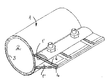
Fig~ 1 is a perspective view of the new means, wh;le
/

Fig~ 2 is a cross section thereof~
Fig, 3 is a plan view thereof~
Figs~ 4 and 5 illustrate end and plan views without some parts,
Fig, 6 is an end view of an embodiment of the inventlon, while
Fig, 7 is a further embodiment of the new means,
Turning first to Fig, l, the clamping and coupling means comprise
the metal band 1, In practice, when actually used, the band is placed
in a sleeve like manner around the tWD pipe ends to be connecte~
preferably with the interposition of a packing 3, or around the conduit
which has sprung a leak, at the damaged part thereof, whereupon both
free edge portions 1' of the sleeve 1 are extended and bent radially
outwardly of the circular space 2 of the sleeve 1.
Extensions 1' are further bent radially enclosing two complementary
plates 4 reinforcing said extensions. Extensions 1' are preferably
provided wlth bulge like protrusions 5, in the centre of which there is
provided a hole 9 where a plurality of nuts and bolts 6 is provided.
The bolts passing through plates 4 and extension 1' and through semi-
spherical protrusions 5. A further plate 7 is provided to enable
apply;ng pressure on said extension~
By tightening bolts 6, section 1' are drawn together in an obvious
manner, Spherical protrusions 5 enable said nuts and bolts to remain
parallel to each other, whether said means are in an "open" position
or "closed" position.

As can be seen, the two extension portions 1' are not parallel
to each other but incli~e such that by tightening bolts 6 the free
edge of said extension engages each other acting as an axis which
enables the tightening properly, In order to place the new means
over a given pipe slots 8 are provided in extension 1' which enables
the insertion of said extension without removing bolt.6~
Fig. 6 illustrates an embodiment of the means according to the
invention where instead of the spheric bulge 5 extensions 1' are bent
;n a wavy line forming a continuous longitudinal convex bulge, while
the free edges are adapted to engage when bolt 6 is tightened~
Fig, 7 illustrates a further embodiment of the invention, Like;
wise sleeve 1 is provided with free edge portions 1', how.ever these
being extended and bent around a rigid body 10 , Bolts 6 pass through
bores 10' and through semi spherical pressure plate 7; One side of
extension 1' is provided with a slot 8 which enables the placing or
re1easing of the sleeve without.removing bolt 6 only by passing sald
slot 8,
By tlghtening bolt 6.sections 1' are drawn together in an obvious
manner~ 5emi spherical pressure plates 7 enable said nut to remain
in the same position. By the tightening of the extreme edges 1`' of
extension .1' it establishes contact and acts as an axis~

5 3
As can he seen from the descri~tfon, the new coupling means
according to the tnvention are unique in their construc~ion by
providing an axls or pfvoting point which enables the tightening
of the coupling means and which acts as counter pofnt,

Representative Drawing
A single figure which represents the drawing illustrating the invention.
Administrative Status

2024-08-01:As part of the Next Generation Patents (NGP) transition, the Canadian Patents Database (CPD) now contains a more detailed Event History, which replicates the Event Log of our new back-office solution.

Please note that "Inactive:" events refers to events no longer in use in our new back-office solution.

For a clearer understanding of the status of the application/patent presented on this page, the site Disclaimer , as well as the definitions for Patent , Event History , Maintenance Fee  and Payment History  should be consulted.

Event History

Description Date
Inactive: Adhoc Request Documented 2018-06-06
Appointment of Agent Requirements Determined Compliant 2018-05-18
Revocation of Agent Requirements Determined Compliant 2018-05-18
Inactive: IPC from MCD 2006-03-11
Time Limit for Reversal Expired 2001-08-20
Application Not Reinstated by Deadline 2001-08-20
Deemed Abandoned - Failure to Respond to Maintenance Fee Notice 2000-08-21
Inactive: Abandon-RFE+Late fee unpaid-Correspondence sent 2000-08-21
Application Published (Open to Public Inspection) 1994-02-27

Abandonment History

Abandonment Date Reason Reinstatement Date
2000-08-21

Maintenance Fee

The last payment was received on 1999-08-19

Note : If the full payment has not been received on or before the date indicated, a further fee may be required which may be one of the following

  • the reinstatement fee;
  • the late payment fee; or
  • additional fee to reverse deemed expiry.

Please refer to the CIPO Patent Fees web page to see all current fee amounts.

Fee History

Fee Type Anniversary Year Due Date Paid Date
MF (application, 4th anniv.) - small 04 1997-08-20 1997-08-20
MF (application, 5th anniv.) - small 05 1998-08-20 1998-06-19
MF (application, 6th anniv.) - small 06 1999-08-20 1999-08-19
Owners on Record

Note: Records showing the ownership history in alphabetical order.

Current Owners on Record
ELIEZER KRAUSZ
Past Owners on Record
None
Past Owners that do not appear in the "Owners on Record" listing will appear in other documentation within the application.
Documents

To view selected files, please enter reCAPTCHA code :


To view images, click a link in the Document Description column. To download the documents, select one or more checkboxes in the first column and then click the "Download Selected in PDF format (Zip Archive)" or the "Download Selected as Single PDF" button.

List of published and non-published patent-specific documents on the CPD .

If you have any difficulty accessing content, you can call the Client Service Centre at 1-866-997-1936 or send them an e-mail at CIPO Client Service Centre.


Document
Description 
Date
(yyyy-mm-dd) 
Number of pages   Size of Image (KB) 
Drawings 1994-02-27 4 56
Claims 1994-02-27 1 29
Abstract 1994-02-27 1 20
Cover Page 1994-02-27 1 12
Descriptions 1994-02-27 5 111
Representative drawing 1999-07-12 1 10
Reminder - Request for Examination 2000-04-25 1 117
Courtesy - Abandonment Letter (Maintenance Fee) 2000-09-18 1 184
Courtesy - Abandonment Letter (Request for Examination) 2000-10-02 1 171
Fees 1997-08-20 1 40
Fees 1998-06-19 1 47
Fees 1999-08-19 1 35
Fees 1996-08-19 1 40
Fees 1995-08-02 1 38