Language selection

Search

Patent 2104577 Summary

Third-party information liability

Some of the information on this Web page has been provided by external sources. The Government of Canada is not responsible for the accuracy, reliability or currency of the information supplied by external sources. Users wishing to rely upon this information should consult directly with the source of the information. Content provided by external sources is not subject to official languages, privacy and accessibility requirements.

Claims and Abstract availability

Any discrepancies in the text and image of the Claims and Abstract are due to differing posting times. Text of the Claims and Abstract are posted:

  • At the time the application is open to public inspection;
  • At the time of issue of the patent (grant).
(12) Patent: (11) CA 2104577
(54) English Title: DEVICE FOR MEASURING A GAS FLOW, AND METHOD FOR USING THE DEVICE
(54) French Title: DISPOSITIF DE MESURE D'UN ECOULEMENT GAZEUX ET METHODE PERMETTANT D'UTILISER LE DISPOSITIF
Status: Expired and beyond the Period of Reversal
Bibliographic Data
(51) International Patent Classification (IPC):
  • G01F 01/68 (2006.01)
  • G01F 01/684 (2006.01)
  • G01P 05/10 (2006.01)
  • G01P 05/12 (2006.01)
(72) Inventors :
  • JOHANSSON, ANDERS (Sweden)
  • GUSTAVSSON, LENNART (Sweden)
(73) Owners :
  • ABB FLAKT AB
(71) Applicants :
  • ABB FLAKT AB (Sweden)
(74) Agent: SMART & BIGGAR LP
(74) Associate agent:
(45) Issued: 2001-10-23
(86) PCT Filing Date: 1992-03-19
(87) Open to Public Inspection: 1992-10-01
Examination requested: 1998-12-11
Availability of licence: N/A
Dedicated to the Public: N/A
(25) Language of filing: English

Patent Cooperation Treaty (PCT): Yes
(86) PCT Filing Number: PCT/SE1992/000169
(87) International Publication Number: SE1992000169
(85) National Entry: 1993-08-20

(30) Application Priority Data:
Application No. Country/Territory Date
9100867-2 (Sweden) 1991-03-22

Abstracts

English Abstract


A device for measuring a gas flow (F) has a measuring body (1) in the form of
a cylinder, and a heating means (12) for
heating the measuring body. A slot (5) extends axially into the cylinder from
one end thereof so as to divide a first portion of the
cylinder into two symmetrical halves (6a, 6b). The heating means (12) is
disposed in a second cylinder portion which is not di-
vided by the slot (5). A temperature sensor (13) is arranged in the second
cylinder portion, and a temperature sensor (14, 15) is
arranged in each cylinder half (6a, 6b). For measuring a gas flow (F), the
measuring body (1) is so disposed in the gas flow that
the slot (5) extends at right angles to the gas flow with one half (6a) facing
the gas flow and with the other half (6b) facing away
from the gas flow. The measuring body (1) is heated by the heating means (12)
to a temperature exceeding the ambient tempera-
ture by a predetermined value. The temperature is measured in each of the two
symmetrical cylinder halves (6a, 6b), whereupon
the gas flow is calculated on the basis of the measured temperatures.


Claims

Note: Claims are shown in the official language in which they were submitted.

7
CLAIMS
1. A device designed for measuring a gas flow (F) and
having a measuring body (1) to be placed in the gas flow,
and a heating means (12) for heating the measuring body in
relation to the environment, characterised in
that the measuring body (1) is in the form of a cylinder
which is symmetrical with respect to a plane of symmetry
extending through the axis of the cylinder, that a slot
(5), containing said plane of symmetry, extends axially a
certain distance into the cylinder from one end thereof, so
as to divide a first portion of the cylinder into two
halves (6a, 6b) which are symmetrical with respect to said
slot (5), that the heating means (12) is provided at a
distance from the bottom (10) of the slot (5) in a second
portion of the cylinder which is not divided by the slot
(5), that a temperature sensor (13) is provided in said
second portion of the cylinder adjacent the bottom (10) of
the slot (5) for measuring the temperature to which the
measuring body (1) is heated by the heating means (12), and
that a temperature sensor (14, 15) is provided in each of
the symmetrical cylinder halves (6a, 6b) adjacent said one
end of the cylinder for measuring the temperature in the
respective half.
2. Device as claimed in claim 1, charac -
terised in that the measuring body (1) is in the
form of a straight circular cylinder.
3. A method for using the device as claimed in claim 1
for measuring a gas flow ( F ), characterised
by so disposing the measuring body (1) in the gas flow (F)
that the slot (5) extends at right angles to the gas flow
with one half (6a) facing the gas flow and with the other
halt (6b) facing away from the gas flow, heating the
measuring body (1) by the heating means (12) to a tempera-
ture exceeding the ambient temperature by a predetermined
value, measuring the temperature in each of the two sym-
metrical cylinder halves (6a, 6b), and calculating the gas
flow on the basis of the measured temperatures.

Description

Note: Descriptions are shown in the official language in which they were submitted.


i
V~!.,'~~92/16848 ~ ~ ,, r' PCT/SE92/00169
DEVICE FOR MEASURING A GAS FLOW, AND METHOD FOR USING THE
DEVICE
The present invention relates to a device designed
far measuring a gas flow and having a measuring body to be
placed in the gas flow, and a heating means for heating
the measuring body in relation to the environment. The
invention also relates to a method for using the device.
A typical spray booth line for painting car bodies is
divided into a plurality of successive sections which by
means of fans are supplied with vertical supply air flows
through filter roofs provided in the sections. In those
sections where the car bodies are sprayed with paint,
exhaust air flows polluted with paint particles and
solvents are evacuated by means of fans. In order that
polluted air should not spread horizontally from the spray
sections to the other sections, it is vital that the
horizontal air flows between the sections be directed
towards the spray sections. It is also vital that the
horizontal air flows be small in relation to the supply
and exhaust air flows so as not to create secondary eddies
in the spray sections or entail that paint particles are
transferred from one car body to another. The horizontal
air flows are suitably regulated by such a speed control
of the supply air fans that the size and the direction of
the horizontal air flows will become as desired. To permit
carrying out this control in optimum fashion, the horizon-
tal air flows must be accurately measured.
Thermal flow transducers, i.e. transducers having a
measuring body which should be placed in the flow to be
measured, and a means for heating the measuring body, and
relying in different ways on the fact that the flow cools
the heated measuring body, are known in various designs.
However, none of the prior-art flow transducers can be con-
sidered to comply with the requirements 1-3 which are list-
ed below and which must be placed on a flaw transducer to
be used in a spray booth line of the type described above.

i
WO 92/16848 M PCT/S E92/00169
210 4~'~ ~I ::
1) Since a spray booth line is classified as explos-
ive environment, the measuring body of the flow transducer
may only be heated to a temperature which but insignifi- '
cantly exceeds the ambient temperature.
2) The flow transducer must be relatively insensitive '
to deposits of paint and other chemicals on the measuring
body.
3) The flow transducer must have a high sensitivity
in the range around zero, especially in the range -2 m/s -
+2 m/s.
The main object of the present invention is to pro-
vide a flow transducer meeting these requirements.
This object is achieved by means of a device which is
of the type described by way of introduction and which
according to the present invention is characterised in
that the measuring body is in the form of a cylinder which
is symmetrical with respect to a plane of symmetry extend-
ing through the axis of the cylinder, that a slot, con-
taining said plane of symmetry, extends axially a certain
distance into the cylinder from one end thereof, so as to
divide a first portion of the cylinder into two halves
which are symmetrical with respect to said slot, that the
heating means is provided at a distance from the bottom of
the slot in a second portion of the cylinder which is not
divided by the slot, that a temperature sensor is provided
in said second portion of the cylinder adjacent the bottom
of the slot for measuring the temperature to which the
measuring body is heated by the heating means, and that a
. temperature sensor is provided in each of the symmetrical
cylinder halves adjacent said one end of the cylinder for
measuring the temperature in the respective half.
The measuring body preferably is in the form of a
straight circular cylinder.
Another object of the present invention is to provide
a suitable method for using this device.

WO 92/16848 ~ ~ ~ PCT/SE92/00169
C'~V;:i E
3
According to the invention, this object is achieved
by a method which is characterised by so disposing the
measuring body in the gas flow that the slot extends at
right angles to the gas flow with one half facing the gas
flow and with the other half facing away from the gas
flow, heating the measuring body by the heating means to a
temperature exceeding the ambient temperature by a pre-
determined value, measuring the temperature in each of the
two symmetrical cylinder halves, and calculating the gas
flow on the basis of the measured temperatures.
The invention will now be described in more detail
with reference to the accompanying drawing.
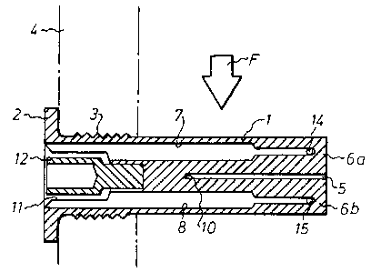
Fig. 1 is an axial longitudinal section of a measur-
ing device according to the present invention.
Fig. 2 is an axial longitudinal section of the
measuring device at right angles to the section in Fig. 1.
Fig. 3 is an end view showing the measuring device,
with the heating means removed, from the left in Fig. 1.
Fig. 4 is an end view showing the measuring device
from the right in Fig. 1.
The measuring device shown in the drawing has a
measuring body 1 formed as a single piece and consisting
of brass. The measuring body 1 is in the form of a
straight, circular cylinder which at one end has a circum-
ferential flange 2 and a grooved portion 3 located inward-
ly of the flange. The flange 2 and the grooved portion 3
are used for fixing the device in a wall 4, through which
the device extends into a gas flow F, e.g. an air flow,
that is to be measured.
At its end opposite the flange 2 the measuring body 1
has a diametrical slot 5 extending axially from this end a
certain distance into the measuring body 1. Thus, the slot
5 divides a portion of the cylinder into two similar
halves 6a and 6b. As appears from Fig. 1, the measuring
body 1 is so disposed in the gas flow F that the slot 5
will extend at right angles to the gas flow, with one
cylinder half 6a facing the gas flow and with the other

WO 92/16848 ~~ ~ ~ PCT/SE92/00169
~;..,
:...4 1
4
cylinder half 6b facing away from the gas flow. 3
Three axially directed.shoulder bores 7, 8 and 9,
whose centre lines are located at the same distance from
the axis of the cylinder and offset 90° with respect to v
each other (see Fig. 3), extend into the measuring body 1
from its flanged end. The shoulder bores 7 and 8 are
located diametrically opposite each other, and the
connecting line between their centre lines is perpen-
dicular to the slot 5 (see Fig. 3). The shoulder bores 7
and 8 each extend equally far into one cylinder half 6a
and 6b, respectively, to a position just inside the
slotted end of the measuring body 1. The shoulder bore 9
is located opposite the slot 5 (see Fig. 3). However, it
does riot extend as far as the slot, but ends a short
distance from the bottom 10 of the slot (see Fig. 2).
A shoulder bore 11 extends along the axis of the
cylinder some distance into the measuring body 1 from the
flanged end thereof. The inner, narrower portion of the
bore 11 is threaded (not shown). A heating means 12 is
screwed into the shoulder bore 11 and, additionally, is
fixed therein by means of an epoxy glue having good ther-
mal conductivity. The heating means 12, containing a heat-
ing resistor (not shown), is adapted to heat the measuring
body 1 to a temperature exceeding the ambient temperature
by a predetermined, relatively low value, e.g. 10°C.
The temperature of the measuring body 1 is measured
by means of a temperature sensor 13 disposed at the bottom
of the shoulder bore 9. In this case, the temperature sen-
sor 13 is a resistance thermometer with a platinum resis-
tance wire having a resistance of 100 n at 0°G.
The temperature of the two cylinder halves 6a and 6b
is measured by means of two temperature sensors 14 and 15
disposed at the bottom of the shoulder bores ? and 8,
respecitvely. Each of the temperature sensors 14 and 15
here consists of two resistance thermometers, each having a
platinum resistance wire of a resistance of 100 !1 at 0°C.

WO 92/16848 O a '~~ PCT/SE92/00169 a
The shoulder bores 7, 8 and 9 are filled with epoxy
glue having good thermal conductivity. The four resistance
thermometers in the temperature sensors 14 and 15 are
connected in a measuring bridge via connecting wires (not
5 shown) running from the sensors to the outside of the
measuring body 1 via the epoxy glue in the shoulder bores
7 and 8. The connecting wires (not shown) of the tempera-
ture sensor 13 similarly run from the sensor to the out-
side of the measuring body 1 via the epoxy glue in the
bore 9.
When the measuring device is to be used, the measur-
ing body 1 is placed in the gas flow F in the manner shown
in Fig. 1. The measuring body 1 is heated to a temperature
which is 10°C above the ambient temperature, which is
measured by a separate temperature transducer. The gas
flow F cools the measuring body 1, the cylinder half 6a
facing the gas flow F being cooled to a greater extent
than the other cylinder half 6b. The temperature differ-
ence between the two cylinder halves 6a and 6b is measured
by means of the temperature sensors 14 and 15, whereupon
the gas flow is calculated on the basis of the measured
temperature difference.
Theoretically, this temperature difference dT is a
function of seueral parameters:
dT = f(aAl/KA2,Q,T)
where a is the coefficient of heat transfer between the
measuring body 1 and the gas, K is the heat conductivity
of the measuring body 1, A1 is the area of the circum-
ferential surface of the portion of the measuring body 1
through which the slot 5 extends, A2 is the cross-sec-
tional area of the measuring body 1, Q is the gas flow,
and T is the difference between the temperature of the
measuring body 1 and the ambient temperature. dT is
proportional to aAl/KA2. Since A1 = rc~d~L, where d is the
diameter of the measuring body 1 and L is the depth or
axial length of the slot 5, and A2 = n d2/4, it is
possible in actual practice to increase the sensitivity of

WO 92/16848 ~~ ~~ ~ PCT/SE92/00169
l
6
the measuring device by increasing, within certain limits,
the depth L of the slot 5 and/or decreasing the diameter d
of the measuring body 1.
The invention is not restricted to the embodiment
described above, but may be modified in several different
ways within the scope of the accompanying claims. For
instance, the measuring body is not necessarily a straight,
circular cylinder, but may be a cylinder otherwise design-
ed. However, the cylinder should be symmetrical with re-
:.
spect to a plane of symmetry extending through the axis of
the cylinder, such that the slot can divide a portion of
the cylinder into two halves which are symmetrical with
respect to the slot.
20
30

Representative Drawing
A single figure which represents the drawing illustrating the invention.
Administrative Status

2024-08-01:As part of the Next Generation Patents (NGP) transition, the Canadian Patents Database (CPD) now contains a more detailed Event History, which replicates the Event Log of our new back-office solution.

Please note that "Inactive:" events refers to events no longer in use in our new back-office solution.

For a clearer understanding of the status of the application/patent presented on this page, the site Disclaimer , as well as the definitions for Patent , Event History , Maintenance Fee  and Payment History  should be consulted.

Event History

Description Date
Inactive: IPC from MCD 2006-03-11
Time Limit for Reversal Expired 2003-03-19
Letter Sent 2002-03-19
Grant by Issuance 2001-10-23
Inactive: Cover page published 2001-10-22
Inactive: Final fee received 2001-07-12
Pre-grant 2001-07-12
Notice of Allowance is Issued 2001-02-20
Letter Sent 2001-02-20
Inactive: Approved for allowance (AFA) 2001-02-02
Inactive: RFE acknowledged - Prior art enquiry 1999-01-06
Inactive: Status info is complete as of Log entry date 1999-01-06
Inactive: Application prosecuted on TS as of Log entry date 1999-01-06
Amendment Received - Voluntary Amendment 1999-01-05
All Requirements for Examination Determined Compliant 1998-12-11
Request for Examination Requirements Determined Compliant 1998-12-11
Application Published (Open to Public Inspection) 1992-10-01

Abandonment History

There is no abandonment history.

Maintenance Fee

The last payment was received on 2001-02-01

Note : If the full payment has not been received on or before the date indicated, a further fee may be required which may be one of the following

  • the reinstatement fee;
  • the late payment fee; or
  • additional fee to reverse deemed expiry.

Patent fees are adjusted on the 1st of January every year. The amounts above are the current amounts if received by December 31 of the current year.
Please refer to the CIPO Patent Fees web page to see all current fee amounts.

Fee History

Fee Type Anniversary Year Due Date Paid Date
MF (application, 6th anniv.) - standard 06 1998-03-19 1998-02-23
Request for examination - standard 1998-12-11
MF (application, 7th anniv.) - standard 07 1999-03-19 1999-02-17
MF (application, 8th anniv.) - standard 08 2000-03-20 2000-02-16
MF (application, 9th anniv.) - standard 09 2001-03-19 2001-02-01
Final fee - standard 2001-07-12
Owners on Record

Note: Records showing the ownership history in alphabetical order.

Current Owners on Record
ABB FLAKT AB
Past Owners on Record
ANDERS JOHANSSON
LENNART GUSTAVSSON
Past Owners that do not appear in the "Owners on Record" listing will appear in other documentation within the application.
Documents

To view selected files, please enter reCAPTCHA code :


To view images, click a link in the Document Description column. To download the documents, select one or more checkboxes in the first column and then click the "Download Selected in PDF format (Zip Archive)" or the "Download Selected as Single PDF" button.

List of published and non-published patent-specific documents on the CPD .

If you have any difficulty accessing content, you can call the Client Service Centre at 1-866-997-1936 or send them an e-mail at CIPO Client Service Centre.


Document
Description 
Date
(yyyy-mm-dd) 
Number of pages   Size of Image (KB) 
Representative drawing 1998-11-18 1 10
Abstract 1995-08-16 1 70
Claims 1994-04-29 1 43
Drawings 1994-04-29 1 20
Description 1994-04-29 6 235
Representative drawing 2001-10-02 1 10
Reminder - Request for Examination 1998-11-22 1 116
Acknowledgement of Request for Examination 1999-01-05 1 172
Commissioner's Notice - Application Found Allowable 2001-02-19 1 164
Maintenance Fee Notice 2002-04-15 1 179
PCT 1993-08-19 9 292
Correspondence 2001-07-11 1 39
Fees 1997-02-24 1 70
Fees 1996-02-26 1 72
Fees 1995-02-20 1 50
Fees 1994-02-24 1 54