Language selection

Search

Patent 2104705 Summary

Third-party information liability

Some of the information on this Web page has been provided by external sources. The Government of Canada is not responsible for the accuracy, reliability or currency of the information supplied by external sources. Users wishing to rely upon this information should consult directly with the source of the information. Content provided by external sources is not subject to official languages, privacy and accessibility requirements.

Claims and Abstract availability

Any discrepancies in the text and image of the Claims and Abstract are due to differing posting times. Text of the Claims and Abstract are posted:

  • At the time the application is open to public inspection;
  • At the time of issue of the patent (grant).
(12) Patent: (11) CA 2104705
(54) English Title: DRILLING DEVICE FOR A ROCK DRILL
(54) French Title: DISPOSITIF DE FORAGE POUR PERFORATRICE DE ROCHES
Status: Expired and beyond the Period of Reversal
Bibliographic Data
(51) International Patent Classification (IPC):
  • E21B 06/00 (2006.01)
  • B25D 09/12 (2006.01)
  • B25D 09/22 (2006.01)
  • B25D 16/00 (2006.01)
(72) Inventors :
  • MUNDJAR, MARJAN (Switzerland)
(73) Owners :
  • SIG SCHWEIZERISCHE INDUSTRIE-GESELLSCHAFT
(71) Applicants :
  • SIG SCHWEIZERISCHE INDUSTRIE-GESELLSCHAFT (Switzerland)
(74) Agent: LAVERY, DE BILLY, LLP
(74) Associate agent:
(45) Issued: 2003-08-05
(22) Filed Date: 1993-08-24
(41) Open to Public Inspection: 1994-03-01
Examination requested: 2000-06-05
Availability of licence: N/A
Dedicated to the Public: N/A
(25) Language of filing: English

Patent Cooperation Treaty (PCT): No

(30) Application Priority Data:
Application No. Country/Territory Date
4-232.294 (Japan) 1992-08-31

Abstracts

English Abstract


The invention concerns a rock drill (2) for activating a
rotatable and reciprocable drill steel assembly (Fig. 1). A
reversible motor (50) is coupled to a striking bar (3) for
rotating the drill steel. The striking bar is struck by a
percussion piston (10). A rotary fluid valve (15) is operat-
ing the piston. A disconnectable coupling (37,38,43) in nor-
mal operation couples both the valve (15) and the striking
bar (3) with the motor (50). In special modes the motor
operates only the percussion piston, e.g. for retracting a
drill rod, or only rotates the striking bar (3), e.g. for
connecting and disconnecting drill rods.


Claims

Note: Claims are shown in the official language in which they were submitted.

What is claimed is:
1. A drilling device for a drill steel, comprising:
- a housing (2);
- a striking bar (3) for holding a rear end of said drill
steel, said striking bar being supported in said housing
(2) for rotation around an axis of said striking bar and
for reciprocal movement along said axis;
- a reversible first fluid motor (50, 60) having an output
shaft (49, 62) coupled to said striking bar (3) for
rotating said striking bar;
- a percussion piston (10) for striking said striking bar
(3), said piston being reciprocatingly received in a
cylinder (14);
a fluid valve (15) connected to said cylinder (14) for
reciprocating said piston (10) by periodic pressure
changes; and
- a disconnectable first mechanical coupling (37, 38)
between said output shaft (49, 62) and said fluid valve
(15) for coupling a valve member of said fluid valve (15)
with said output shaft.
2. The drilling device according to claim 1, further including
a disconnectable second mechanical coupling (38, 37)
connecting said output shaft (49) with said striking bar
(3).
3. The drilling device according to claim 1, further comprising
a second fluid motor (50) coupled to said fluid valve (15).
4. A drilling device for a drill steel, comprising:
- a housing (2);
- a striking bar (3) for holding a rear end of said drill
steel, said striking bar being supported in said housing

for rotation around a striking bar axis and for
reciprocal movement along said axis;
- a reversible first fluid motor (50, 60) having a first
output shaft (49, 62);
- a percussion piston (10) for striking said bar (3), said
piston being reciprocatingly received in a cylinder (14)
of said housing;
- a fluid valve (15) connected to said cylinder (14) for
controlling periodic pressure changes within said
cylinder to reciprocate said piston;
- a fixed-ratio transmission (38, 43; 38, 37) connecting
said first output shaft (49, 62) to said striking bar to
rotate said striking bar and connecting said first output
shaft (49, 62) to said fluid valve (15) for controlling a
reciprocation frequency of said percussion piston, said
transmission being selectively engageable; and
- means for selectively engaging said transmission.
5. The drilling device according to claim 4, wherein said
transmission includes rotary gears selectively engaged by
relative axial sliding of said gears to selectively mesh and
disconnect teeth of said gears.
6. The drilling device according to claim 4, wherein said
transmission further comprises:
- a fixed-ratio first transmission (38, 43) connecting said
first output shaft (49, 62) to said fluid valve (15) for
controlling a reciprocation frequency of said percussion
piston, said first transmission being selectively
engageable; and
- a fixed-ratio second transmission (38, 37) connecting
said first output shaft (49, 62) to said striking bar to
rotate said striking bar, said second transmission being
selectively engageable.

7. The drilling device according to claim 6, wherein said first
transmission and said second transmission include rotary
gears and are selectively engaged by relative axial sliding
of said gears to selectively mesh and disconnect teeth of
said gears.
8. The drilling device according to claim 6, wherein said means
for selectively engaging includes means for selectively
engaging said first transmission and said second
transmission.
9. The drilling device according to claim 8, wherein said means
for selectively engaging said first transmission and said
second transmission allows for engaging the first
transmission but not the second transmission;
allows for engaging the second transmission but not the
first transmission; and
allows for engaging simultaneously the first transmission
and the second transmission.
10. The drilling device according to claim 9, wherein said first
transmission and said second transmission include rotary
gears and are selectively engaged by relative axial sliding
of said gears to mesh and disconnect teeth of said gears.
11. The drilling device according to claim 4, further
comprising:
- a second motor (50);
- and a second output shaft (62) coupled to said second
motor (50);
- said second output shaft (49) directly coupled to said
fluid valve for controlling a reciprocation frequency of
said percussion piston;
- said first output shaft (62) is directly coupled to said
striking bar to rotate said striking bar;

- said transmission connects said first output shaft (62)
to said fluid valve (15) for controlling a reciprocation
frequency of said percussion piston and connects said
second output shaft (49) to said striking bar to rotate
said striking bar; and
- said means for selectively engaging includes means for
disengaging said second output shaft (49) from said
striking bar, whereby said second output shaft will not
rotate said striking bar through said transmission.
12. The drilling device according to claim 11, wherein said
transmission includes rotary gears selectively engaged by
relative axial sliding of said gears to selectively mesh and
disconnect teeth of said gears.
13. A drilling device for a drill steel, comprising:
- a housing (2);
- a striking bar (3) for holding a rear end of said drill
steel, said striking bar being supported in said housing
(2) for rotation around its axis and for reciprocal
movement along its axis;
- a reversible first fluid motor (60) with an output shaft
(62) coupled to said striking bar (3) for rotating said
striking bar;
- a percussion piston (10) for striking said striking bar
(3) and reciprocatingly received in a cylinder (14);
- a fluid valve (15) connected to said cylinder (14) for
reciprocating said piston (10); and
- a disconnectable first coupling (37,38) between said
output shaft (62) and said fluid valve (15);
- further comprising a second fluid motor (50) coupled to
said fluid valve (15).

Description

Note: Descriptions are shown in the official language in which they were submitted.


CA 02104705 2000-08-04
1
OM/ru
Drilling Device for a Rock Drill
Background of the invention
This invention relates to a drilling device for a rock drill
with a rotary drive for the drill steel and a percussion
mechanism.
A hydraulic rock drill is known through U.S. Patent No.
4,064,950 in which the control valves for percussion power
and rotation speed are located in the control panel apart
from the rock drill itself. Furthermore, the percussion
apparatus and the rotation motor have separate hydraulic
circuits. The maximum percussion power is adjusted by a
pressure relief valve in the hydraulic circuit of the
percussion mechanism and the maximum rotation power is
adjusted by a pressure relief valve in the hydraulic circuit
of the rotary mechanism.

2
With such drilling devices it sometimes happens that the
drill steel gets jammed and cannot be rotated further. When
under such conditions the percussion mechanism continues to
strike the drill steel, it can happen that the latter is
driven into the rock and cannot be retracted any more.
In the German Offenlegungsschrift No. 34 39 268 a similar
drilling device has been proposed where the percussion
mechanism and the hydraulic motor are arranged in series.
This device does not have the drawback mentioned above:
When the hydraulic fluid cannot flow through the motor
because the motor is stopped by the drill then no flow passes
through the percussion mechanism. Therefore, percussion stops
when the drill rod gets jammed. However, this prior art
device has other drawbacks: The sum of the power output of
the hydraulic motor and the percussion mechanism is constant
but the power distribution between the two is indetermined.
In Swiss Patent No. 559 088 it was proposed to directly
couple the percussion frequency with the rotation rate of the
motor. However, with this proposal it is not possible to
operate the percussion mechanism and the motor independently.

3
Summary of the invention
The object of the present invention is to create a drilling
device which does not have the drawbacks mentioned above.
The drilling device of the present invention has a housing in
which a striking bar is rotatably and reciprocably supported.
The output shaft of a reversible fluid motor is coupled to
the striking bar for rotating the drill steel. A percussion
piston reciprocatingly received in a cylinder strikes on to
the striking bar. A rotary fluid valve is connected to the
cylinder. A releasable coupling selectively couples the out-
put shaft with the rotary valve.
The rotary valve may have an additional independent drive
motor or a second releasable coupling may be arranged bet-
ween the output shaft and the striking bar. During normal
operation the rotary valve is directly coupled with the out-
put shaft of the drill motor. The percussion frequency is
exactly proportional to the rotation rate of the drill steel.
The angle which the drill head shifts between two successive
blows by the percussion, piston is always the same regardless
of the rotation rate. It,can be shown that this represents
about the optimum adjustment of percussion frequency to the

4
~~.~~~~~U~
rotation rate which varies as the drill steel on its advance
encounters rock formations of different properties and hard-
ness.
This automatic internal adjustment of the percussion fre-
quency, therefore, guarantees maximum drill performance in
different rock formations.
If the drill steel for some reason gets jammed in the rock
then the percussion stops immediately. It is therefore
possible to reverse the direction of force on the drill steel
and retract it. This saves considerable time and drilling
equipment.
When retracting a drill steel which is assembled from a
number of sections, these sections must be disconnected
successively. To that end, the rear e:nd of a following
section still partly inserted in the drill bore is clamped.
The 'threaded connection between that section and the previous
section that is still clamped in the drilling device, can now
be rattled loose by independently operating only the percus-
sion mechanism. The previous section can now be unscrewed by
operating the drill motor in the proper rotation sense which
is contra to the drilling mode.
All these operations must be performed under remote control
because generally operators are not permitted near the drill-

5
t;:~~~.~ ~~~~
ing process because of safety reasons due to the hazard of
falling rock.
For the above reasons the drilling device according to the
present invention guarantees an optimum use of the rock
drills under various rock conditions. At the same time it
allows remote control of coupling and uncoupling in the event
of long hole drilling.
brief description of the drawings
Embodiments of the present invention will now be described
with reference to the drawings, in which
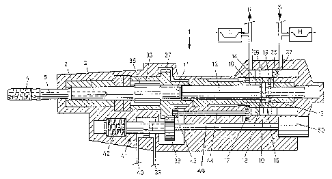
Fig. 1 shows a longitudinal section through a first
embodiment,
Fig. 2 shows a detail of the rotary valve, and
Fig. 3 shows a longitudinal section through a second
embodiment.
detailed description of preferred eanbodiments
The drilling device 1 according to Fig. Z comprises a housing
2 which reciprocatingly and rotably activates a striking bar
3. On its forward end, the striking bar 3 may have a male

6
w~~'-~ ~~
thread 4 for connecting the drill steel (not shown). The
striking bar 3 also has an internal bore 5 for supplying a
flushing fluid to the drill face via a connection (not shown)
to the housing 2.
Coaxial with the striking bar a percussion piston 10 is
reciprocatingly received in the housing 2. In operation the
front face 11 of the piston rod 12 of piston 10 strikes
against the rear face of the striking bar 3. The piston 10
slides in a bore 13 of a cylinder 14. The cylinder 14 is
notably supported in housing 2 and forms part of a rotary
valve 15. On its forward end it bears gear teeth 16 linking
with a pinion I7. The cylinder 14 has two sets of openings
18, 19 in two radial planes, The openings 18, 19 are regul-
arly spaced in the circumferential direction, and the open-
ings 18 are angularly offset against the openings 19.
The outer surface 20 of the cylinder Z4 bears against a
cylindrical, meander shaped second valve member 25 of rotary
valve 15. A developed projection on the outer cylindrical
surface 26 of part of valve member 25 and cylinder 14 is
shown in Fig. 2. One axial face 27 and therefore half of the
slots 28 of the meander is pressurised with supply pressure
and connected to a high pressure hydraulic accumulator H and
to a supply line S. The other axial face 29 and the other
slots 30 are connected to a low pressure accumulator L and a
return line R.

7
E~~~ ~ ~~~
The above is a somewhat simplified description of rotary
valve 15. A more detailed description is contained in Swiss
Patent No. 559 088.
In operation the valve member 25 remains fixed with housing
2. When the cylinder 14 rotates the openings 18 communicate
alternatively with the supply arid the return and the openings
19 alternatively with the return and the supply so that
piston 10 reciprocates and hits on to the striking bar with a
frequency proportional to the rotation rate of cylinder 14.
The striking bar 3 has a splined shaft section 35 which
communicates with a splined bushing 36 connected to a gear
37. Gear 37 communicates with a further gear 38 which can be
axially shifted from the normal position shown in Fig. 1 in
two switch positions by supplying one: or the other input line
39, 40 of a hydraulic cylinder 41 with pressure fluid. When
pressure is released from both input:. 39, 40 the gear 38
returns to the neutral position by a centering spring 42. In
the neutral position the gear 38 links with gear 37 and a
pinion 43 which is coupled to pinion 17 by a shaft 44.
The internal bore of gear 38 is splined and sits on the
splined end of an output shaft 49 of a reversible hydraulic
motor 50. When gear 38 is shifted in its one end position it
links with pinion 43 only and therefore only the percussion

8
~~.Ut~ ~~~
mechanism is in operation. This mode of operation is useful
for transferring impacts to the threaded ends between two
drill steels for loosening the coupling. When the gear 38 is
shifted to the opposite end position it links exclusively
with gear 37 so that the drill steel is rotated and the per-
cussion mechanism is not operative. This mode of operation is
useful for connecting and disconnecting drill rods and in
some particular rock formations, far rotational drilling
only.
In normal application, however, the gear 38 is in the neutral
position shown in Fig. 1 so that the percussion frequency is
proportional to the rotation rate of the drill rod. This
proportionality provides optimum performance in most drilling
applications, irrespective of the rock conditions.
In the embodiment shown in Fig. 3 lil!;e parts are designated
with like reference numerals so that a detailed description
of those parts need not be repeated.
The basic difference between the two embodiments is that in
the Fig. 3 embodiment percussion and drill rotation can addi-
tionally be performed with individual motors 50, 60. To that
end, a pinion 61 on an output shaft 62 of hydraulic motor 60
links with gear 37. Gears 37, 38 normally link so that motor
60 is the main motor. In normal operation motor 50 is idling,
its two lines being connected to the return:

9
:~.lU-:~'l~~
If pressure is applied to input 39 the piston 41 pulls gear
38 out of engagement with gear 37. The rotary valve 15 can
now either be kept at rest (no percussion), or it can be
operated at a frequency independent of the rotation rate of
the drill rod by operating motor 50 via gears 63, 17. This
may be of advantage in some particular rock formations.
The embodiment of F'ig. 3 is therefore somewhat more versatile
whereas the embodiment of Fig. 1 is less expensive.

Representative Drawing
A single figure which represents the drawing illustrating the invention.
Administrative Status

2024-08-01:As part of the Next Generation Patents (NGP) transition, the Canadian Patents Database (CPD) now contains a more detailed Event History, which replicates the Event Log of our new back-office solution.

Please note that "Inactive:" events refers to events no longer in use in our new back-office solution.

For a clearer understanding of the status of the application/patent presented on this page, the site Disclaimer , as well as the definitions for Patent , Event History , Maintenance Fee  and Payment History  should be consulted.

Event History

Description Date
Inactive: IPC deactivated 2011-07-27
Inactive: IPC from MCD 2006-03-11
Inactive: First IPC derived 2006-03-11
Inactive: IPC from MCD 2006-03-11
Time Limit for Reversal Expired 2005-08-24
Letter Sent 2004-08-24
Grant by Issuance 2003-08-05
Inactive: Cover page published 2003-08-04
Inactive: Final fee received 2003-05-20
Pre-grant 2003-05-20
Letter Sent 2003-04-10
Notice of Allowance is Issued 2003-04-10
Inactive: Approved for allowance (AFA) 2003-03-31
Amendment Received - Voluntary Amendment 2000-08-04
Inactive: Status info is complete as of Log entry date 2000-06-22
Letter Sent 2000-06-22
Inactive: Application prosecuted on TS as of Log entry date 2000-06-22
All Requirements for Examination Determined Compliant 2000-06-05
Request for Examination Requirements Determined Compliant 2000-06-05
Application Published (Open to Public Inspection) 1994-03-01

Abandonment History

There is no abandonment history.

Maintenance Fee

The last payment was received on 2003-05-21

Note : If the full payment has not been received on or before the date indicated, a further fee may be required which may be one of the following

  • the reinstatement fee;
  • the late payment fee; or
  • additional fee to reverse deemed expiry.

Patent fees are adjusted on the 1st of January every year. The amounts above are the current amounts if received by December 31 of the current year.
Please refer to the CIPO Patent Fees web page to see all current fee amounts.

Fee History

Fee Type Anniversary Year Due Date Paid Date
MF (application, 4th anniv.) - standard 04 1997-08-25 1997-07-09
MF (application, 5th anniv.) - standard 05 1998-08-24 1998-06-23
MF (application, 6th anniv.) - standard 06 1999-08-24 1999-06-18
Request for examination - standard 2000-06-05
MF (application, 7th anniv.) - standard 07 2000-08-24 2000-06-20
MF (application, 8th anniv.) - standard 08 2001-08-24 2001-06-18
MF (application, 9th anniv.) - standard 09 2002-08-26 2002-08-12
Final fee - standard 2003-05-20
MF (application, 10th anniv.) - standard 10 2003-08-25 2003-05-21
Owners on Record

Note: Records showing the ownership history in alphabetical order.

Current Owners on Record
SIG SCHWEIZERISCHE INDUSTRIE-GESELLSCHAFT
Past Owners on Record
MARJAN MUNDJAR
Past Owners that do not appear in the "Owners on Record" listing will appear in other documentation within the application.
Documents

To view selected files, please enter reCAPTCHA code :


To view images, click a link in the Document Description column (Temporarily unavailable). To download the documents, select one or more checkboxes in the first column and then click the "Download Selected in PDF format (Zip Archive)" or the "Download Selected as Single PDF" button.

List of published and non-published patent-specific documents on the CPD .

If you have any difficulty accessing content, you can call the Client Service Centre at 1-866-997-1936 or send them an e-mail at CIPO Client Service Centre.

({010=All Documents, 020=As Filed, 030=As Open to Public Inspection, 040=At Issuance, 050=Examination, 060=Incoming Correspondence, 070=Miscellaneous, 080=Outgoing Correspondence, 090=Payment})


Document
Description 
Date
(yyyy-mm-dd) 
Number of pages   Size of Image (KB) 
Representative drawing 2003-03-31 1 24
Description 2000-08-03 9 232
Drawings 2000-08-03 3 100
Claims 2000-08-03 4 146
Abstract 1994-03-29 1 21
Drawings 1994-03-29 3 106
Claims 1994-03-29 2 42
Description 1994-03-29 9 263
Representative drawing 1998-08-24 1 38
Reminder - Request for Examination 2000-04-25 1 117
Acknowledgement of Request for Examination 2000-06-21 1 177
Commissioner's Notice - Application Found Allowable 2003-04-09 1 160
Maintenance Fee Notice 2004-10-18 1 173
Correspondence 2003-05-19 1 31
Fees 2003-05-20 1 35
Fees 1997-07-08 1 48
Fees 1998-06-22 1 46
Fees 2001-06-17 1 40
Fees 2002-08-11 1 38
Fees 1999-06-17 1 42
Fees 2000-06-19 1 39
Fees 1996-07-15 1 41
Fees 1995-07-06 1 42