Language selection

Search

Patent 2105058 Summary

Third-party information liability

Some of the information on this Web page has been provided by external sources. The Government of Canada is not responsible for the accuracy, reliability or currency of the information supplied by external sources. Users wishing to rely upon this information should consult directly with the source of the information. Content provided by external sources is not subject to official languages, privacy and accessibility requirements.

Claims and Abstract availability

Any discrepancies in the text and image of the Claims and Abstract are due to differing posting times. Text of the Claims and Abstract are posted:

  • At the time the application is open to public inspection;
  • At the time of issue of the patent (grant).
(12) Patent Application: (11) CA 2105058
(54) English Title: MULTICYCLINDER TWO-STROKE ENGINE INTAKE MANIFOLD
(54) French Title: COLLECTEUR D'ADMISSION DE MOTEUR A DEUX TEMPS A PLUSIEURS CYLINDRES
Status: Deemed Abandoned and Beyond the Period of Reinstatement - Pending Response to Notice of Disregarded Communication
Bibliographic Data
(51) International Patent Classification (IPC):
  • F02B 25/26 (2006.01)
  • F02B 75/02 (2006.01)
  • F02M 35/10 (2006.01)
(72) Inventors :
  • SCHLUNKE, CHRISTOPHER KIM (Australia)
  • SEEBER, KENNETH PHILLIP (Australia)
  • HOUSTON, RODNEY ALEXANDER ROWNEY (Australia)
  • SAYER, CHRISTOPHER NEVILLE FRANCIS (Australia)
(73) Owners :
  • ORBITAL ENGINE COMPANY (AUSTRALIA) PTY. LIMITED
(71) Applicants :
(74) Agent: SMART & BIGGAR LP
(74) Associate agent:
(45) Issued:
(86) PCT Filing Date: 1992-03-20
(87) Open to Public Inspection: 1992-10-01
Examination requested: 1999-03-04
Availability of licence: N/A
Dedicated to the Public: N/A
(25) Language of filing: English

Patent Cooperation Treaty (PCT): Yes
(86) PCT Filing Number: PCT/AU1992/000119
(87) International Publication Number: WO 1992016726
(85) National Entry: 1993-08-27

(30) Application Priority Data:
Application No. Country/Territory Date
PK 5250 (Australia) 1991-03-22

Abstracts

English Abstract

2105058 9216726 PCTABS00016
A multicylinder two-stroke cycle internal combustion engine (10)
comprises an individual crankcase cavity (18) for each cylinder
to receive the incoming air charge for that cylinder and a
cylinder block (11) with at least two cylinders having co-operating
crankcase cavities (18) provided with valve controlled intake ports
(19) in a common wall (31) of the cylinder block (11). An air
induction manifold (25) is detachably mounted to the common wall (31)
to form a single air induction cavity (27), at least part of
which is formed within the cylinder block (11), and has a single
main inlet port for regulation of air inflow to the induction cavity
(27). Individual passages (33) communicating each crankcase
cavity inlet port (19) with the air induction cavity (27) are formed
in the manifold (25). Acceptable performance with limited
increase in the overall physical dimensions of the engine (10) can thus
be obtained.


Claims

Note: Claims are shown in the official language in which they were submitted.

PCT/AU/92/00119
THE CLAIMS DEFINING THE INVENTION ARE AS FOLLOWS:
1. A multi-cylinder two stroke cycle internal combustion engine
comprising a cylinder block having at least two cylinders therein, an individualcrankcase cavity for each cylinder to receive the incoming air charge for the
respective cylinder, said crankcase cavities each having respective valve
controlled intake ports in a common wall of the cylinder block, an air inductionmanifold detachably mounted to said common wall of the cylinder block to form
therewith a single air induction cavity communicating with each crankcase cavityinlet port, at least part of said air induction cavity being formed within the cylinder
block, and at least one inlet port in said manifold for the entry of air to saidinduction cavity.
2. A multi-cylinder engine as claimed in claim 1, wherein said
cylinder block further comprises:
a planar face with a first opening communicating with an internal
cavity within the confines of the block, said internal cavity being closed apartfrom said first opening to form part of said induction cavity opening, and
respective second openings in the block forming or communicating with said air
intake ports to the respective crankcase cavities.
3. A multi-cylinder engine as claimed in claim 2 wherein said
manifold comprises a planar face complementary to the cylinder block planar
face and having formed therein complementary first and second openings so
that when said respective planar faces are in abutting relation said first and
second openings of the cylinder block planar face are in register with said
complementary first and second openings of the manifold planar face.
4. A multi-cylinder engine as claimed in any one of claims 1 to 3,
wherein individual passages are formed in said induction manifold to provide
the communication between the cavity and the respective intake ports.

PCT/AU92/000119
5. A multi-cylinder engine as claimed in claim 4 wherein said
passages formed in said manifold communicating each crankcase cavity inlet
port with the air induction cavity are of a length determined to be tuned to theoperation of the engine in a selected speed range.
6. A multi-cylinder engine as claimed in claim 4 or 5 wherein a
substantial portion of the length of said passages communicating each
crankcase cavity inlet port with the air induction cavity if formed within the
confines of the manifold.
7. A multi-cylinder engine as claimed in claim 6 wherein the level of
the manifold intake passage is not higher than the level of a cylinder head
mounted on the cylinder block.
8. A multi-cylinder internal combustion engine comprising a cylinder
block having at least two cylinders therein, an air induction manifold mounted on
said block to define therewith, a single air induction cavity with at least partthereof formed within the confines of the cylinder block, at least one inlet port in
said manifold for the entry of air to said cavity, and a respective passage
communicating said cavity independently with each cylinder of the engine.
9. A multi-cylinder engine as claimed in claim 8 wherein the engine
operates on the four stroke cycle.

Description

Note: Descriptions are shown in the official language in which they were submitted.


WO 92/16726 2 ~ 3 PCl/Al)92/00119
'' ' 1 ! '
MULTICYLINDER ~WO-STF~OKE ENGINE INTAKE MANIFOL~
This invention relates to the construction of the induction manifold
through which the incoming air is distributed to the respective crankcase cavities of a
5 multi-cylinder crankcase compression two stroke cycle engine.
In many multi cylinder ~wo stroke cycle engines, individual
carburettors are provided to regulate the fuel and air supply to the respective
crankcase cavities from which the fuel and air is supplied to the respective cylinders
of the engine. In fuel injected engines it is customary to provide an air induction
10 manifold having a single air iniet, with each crankcase cavity of the engine
communicating directly with the interior of the manifold through a respective
one-way valve.
In a two stroke cycle multi-cylinder engine it is known that from the
point o~ view of performance considerations, where the intake of air to the cylinders
15 is provided from a common manifold, the common manifold should have a capacity at
least equal to the total swept volume o~ the engine, and preferably 1.2 to 1.~ times the
total swept volume of the engine. The provision of a manifold of this capa ity
curren~ly substantially increases the overall physical dimensions of the engine
assembly together with increases in weight and material costs.
It is therefore the object of the present invention to provide a two
stroke cycle multi-cylinder engine having an air intake manifold construction that has
an air capacity appropriate for acceptable performance with limited increase in the
overall physical dimensions of the engine.
With this object in view, there is provided a multi-cylinder two
2~ stroke cycie internal combustion engine comprising a cylinder block having at least
two cylinders therein, an individual crankcase cavity for each cylinder to receive Ihe
incoming air charge for the respective cylinder, said crankcase cavities each having
respective valve controlled intake ports in a common wall of the cylinder block, an air
induction manifold detachably mounted to said common wall of the cylinder block to
3 0 form therewith a single air induction cavity communicating with each crankcase
cavity inlet port, at least part of said air induction cavity being formed within the
cylinder block, and at least one inlet port in said manifold for the entry of air to said
induction cavity.

W092/1fi726 ~a~0~3..~` PCr/~U92/00~19
Preferably individual passages are formed within the induction
manifold to provide the communication between air induction cavity and the respective
intake ports.
Conveniently, the cylinder block has a planar face wilh a first opening
5 therein communicaling with an internal cavity within the confines of the block, that
cavity being closed apart from said first opening, and respective second openings
therein forming, or communicating with, said air intake ports to the respective
crankcase cavities. The manifold may also have a planar face complementary to the
cylinder block planar face, and complementary first and second openings therein so
10 that with said respective planar faces in abutting relation the two first openings and
the respective second openings in the cylinder block and manifold are in registration
with one another.
The incorpora!ion of part of the required air capacity of the induction
manifold within the cylinder block reduces the overall dimension of the engine
15 assembly in width and/or height across the induction manifold without a sacrifice in
the capacity of the air induction cavity and a consequent detraction in engine
performance. There is also a resultant saving in material and weight.
The present invention is also applicable to engines operating on cycles
other than the two stroke cycle, such as on the four stroke cycle, and thus the
20 invention includes a multi cylinder internal combustion engine comprising a cylinder
block having at least two cylinders therein, an air induction manifold mounted on said
block to define therewith a single air induction cavity with at least part thereof
formed within the confines of the cylinder block, at least one inlet port in said
manifold for the entry of air to said cavity, and a respective passage to communicate
2 5 said cavity independently with each cylinder of the engine.
The invention wiil be more readily understood from the Sollowing
description of one practical arrangement of the engine as illustrated in the
accompanying drawings.
In the drawings:
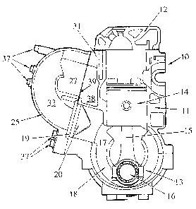
3 0 Figure 1 is a side view of an engine with 1he induction manifold fitted
thereto;
Figure 2 is a sectional view along line 2-2 in Figure 1 with the
addition of the cylinder head and crankcase;
Figure 3 is side view of the cylinder block with the induction manifold
3 ~ removed;
,: . . : .,.............. ,., ., ~ ~.
':.
. . .

WO 92/16726 ~ 8 PCI/AU92/00119
' ! . .
"... ..
Figure 4 is an internal view of the induction manifold removed from
tKe engine.
Referring now to the drawings and particularly Figures 2 and 3 the
engine 10 is of the generally conventional two stroke cycle construction having a
5 cylinder block 11 with three inline cylinders a cylinder head 12 and crankcase 13.
Each piston 14 is coupled by a conventional connecting rod 15 to the crankshaft 16
with the crankcase 13 and lower portion of the cylinder block 11 forming
intermediate walls 17 dividing the crankcase into respective compartments 18 for the
engine to operate on the conventional crankcase compression system.
1 û Each crankcase compartment 18 has an individual inlet port 19 in
which is fitted a conventional reed valve assembly 20 that only permits a flow of air
into the crankcase compartment when the pressure in the compartment is below that
within the manifold 25. Each individual air inlet port 19 is in direct communication
wi~h the main induction chamber 27 of the manifold 25. A rnain intake passage 23 is
15 provided at one end of the manifold communicating with the main induction chamber
27 and having a conventional throttle valve (not shown) mounted therein.
The cyiinder block 11 has an opening ~9 in the wall 31 ~hereof of a
shape to complement the shape of the open side 32 of the manifold 25. The cavi~y 38
provided within the cylinder biock is accessible through the opening 39 in the side
2 0 wall 31 of the cylinder block and is closed against access to atmosphere other than
through the main induction chamber 27 and main air intake passage 23.
The common wall 31 of the cylinder block has a planar surface 35
which extends completely about the periphery of the opening 39 and abou~ each of the
crankcase compartment inlet ports 19. The manifold 25 has a complem2ntary planar2 5 surface 36 which extends completely about the periphery of ~he open side 32 of the
manifold and about each of the passages 33 in the manifold that communicate with the
inlet ports 19 of the crankcase compartments. The manifold is sealably attached to the
cylinder block by the bolts 37 preferably with a gasket therebetween.
Internal passages 33 are formed integral with the manifold 2~ and
3 û located within the chamber 27. Each passage providing communication between the
main induction chamber 27 and the respective inlet ports 19 in the planar face 35 of
the cylinder block.
The passages 33 are of a length determined to be "tuned to the
operation of the engine in a selected speed range to provide improved intake of air to
3 5 the crankcase compar1ments. As seen in FigurP 4 a substantial portion of the length
.

WO 92/16726 PCI/AU9~/001 t9
2~ ~0~3 ~
of the passages 33 is located within the confines of the manifold. This assists in
minimising the overall dimensions of the engine and manifold assembly, particularly
by enabling lhe manifold to be located closer to the cylinder block and the inlet ports to
the respective crankcase compartments while still being of the required tuned length.
This arrangement of the passages 33 within and as part of the manifold
permits simple alteration of the actual length of the passages by merely varying lhe
height of the upper edge 30 of the respective passages 33. Thus the same basic
manifold casting can be used to meet a range of tune~ length inlet of the inlet passages
33, with the heights of the manifold with respect to the engine block unchanged.10 Further the height of the manifold can be reduced to a level not higher than the
cylinder head. Further, as part of the required internal volume of the inductionchamber 27 is provided within the cylinder block, a reduction in overall width of ~he
cylinder block-induction manifold assembly is achieved without reduction in the
required internal volume.
, . ' :'

Representative Drawing
A single figure which represents the drawing illustrating the invention.
Administrative Status

2024-08-01:As part of the Next Generation Patents (NGP) transition, the Canadian Patents Database (CPD) now contains a more detailed Event History, which replicates the Event Log of our new back-office solution.

Please note that "Inactive:" events refers to events no longer in use in our new back-office solution.

For a clearer understanding of the status of the application/patent presented on this page, the site Disclaimer , as well as the definitions for Patent , Event History , Maintenance Fee  and Payment History  should be consulted.

Event History

Description Date
Inactive: IPC from MCD 2006-03-11
Application Not Reinstated by Deadline 2003-11-24
Inactive: Dead - No reply to s.30(2) Rules requisition 2003-11-24
Deemed Abandoned - Failure to Respond to Maintenance Fee Notice 2003-03-20
Inactive: Abandoned - No reply to s.30(2) Rules requisition 2002-11-25
Inactive: S.30(2) Rules - Examiner requisition 2002-05-23
Inactive: Delete abandonment 2000-05-02
Deemed Abandoned - Failure to Respond to Maintenance Fee Notice 2000-03-20
Inactive: Status info is complete as of Log entry date 1999-03-19
Inactive: Application prosecuted on TS as of Log entry date 1999-03-19
Request for Examination Requirements Determined Compliant 1999-03-04
Inactive: RFE acknowledged - Prior art enquiry 1999-03-04
All Requirements for Examination Determined Compliant 1999-03-04
Application Published (Open to Public Inspection) 1992-10-01

Abandonment History

Abandonment Date Reason Reinstatement Date
2003-03-20
2000-03-20

Maintenance Fee

The last payment was received on 

Note : If the full payment has not been received on or before the date indicated, a further fee may be required which may be one of the following

  • the reinstatement fee;
  • the late payment fee; or
  • additional fee to reverse deemed expiry.

Please refer to the CIPO Patent Fees web page to see all current fee amounts.

Fee History

Fee Type Anniversary Year Due Date Paid Date
MF (application, 6th anniv.) - standard 06 1998-03-20 1998-02-24
MF (application, 7th anniv.) - standard 07 1999-03-22 1999-02-18
Request for examination - standard 1999-03-04
MF (application, 8th anniv.) - standard 08 2000-03-20 2000-02-25
MF (application, 9th anniv.) - standard 09 2001-03-20 2001-02-21
MF (application, 10th anniv.) - standard 10 2002-03-20 2002-02-18
MF (application, 2nd anniv.) - standard 02 1994-03-21
Owners on Record

Note: Records showing the ownership history in alphabetical order.

Current Owners on Record
ORBITAL ENGINE COMPANY (AUSTRALIA) PTY. LIMITED
Past Owners on Record
CHRISTOPHER KIM SCHLUNKE
CHRISTOPHER NEVILLE FRANCIS SAYER
KENNETH PHILLIP SEEBER
RODNEY ALEXANDER ROWNEY HOUSTON
Past Owners that do not appear in the "Owners on Record" listing will appear in other documentation within the application.
Documents

To view selected files, please enter reCAPTCHA code :


To view images, click a link in the Document Description column. To download the documents, select one or more checkboxes in the first column and then click the "Download Selected in PDF format (Zip Archive)" or the "Download Selected as Single PDF" button.

List of published and non-published patent-specific documents on the CPD .

If you have any difficulty accessing content, you can call the Client Service Centre at 1-866-997-1936 or send them an e-mail at CIPO Client Service Centre.


Document
Description 
Date
(yyyy-mm-dd) 
Number of pages   Size of Image (KB) 
Representative drawing 1998-11-20 1 12
Representative drawing 2002-05-28 1 13
Abstract 1995-08-17 1 69
Description 1994-07-01 4 167
Cover Page 1994-07-01 1 21
Claims 1994-07-01 2 79
Drawings 1994-07-01 4 84
Claims 1999-04-12 2 83
Reminder - Request for Examination 1998-11-23 1 116
Acknowledgement of Request for Examination 1999-03-04 1 173
Courtesy - Abandonment Letter (R30(2)) 2003-02-03 1 167
Courtesy - Abandonment Letter (Maintenance Fee) 2003-04-17 1 176
PCT 1993-08-27 10 331
Correspondence 2000-05-02 5 180
Fees 1997-02-20 1 63
Fees 1996-02-29 1 50
Fees 1995-03-17 1 50
Fees 1994-03-14 1 37