Language selection

Search

Patent 2105825 Summary

Third-party information liability

Some of the information on this Web page has been provided by external sources. The Government of Canada is not responsible for the accuracy, reliability or currency of the information supplied by external sources. Users wishing to rely upon this information should consult directly with the source of the information. Content provided by external sources is not subject to official languages, privacy and accessibility requirements.

Claims and Abstract availability

Any discrepancies in the text and image of the Claims and Abstract are due to differing posting times. Text of the Claims and Abstract are posted:

  • At the time the application is open to public inspection;
  • At the time of issue of the patent (grant).
(12) Patent: (11) CA 2105825
(54) English Title: INTERNALLY FLASHED SIDING CHANNEL
(54) French Title: GOUTTIERE INTERNE POUR REVETEMENT EXTERIEUR
Status: Expired and beyond the Period of Reversal
Bibliographic Data
(51) International Patent Classification (IPC):
  • E06B 01/00 (2006.01)
  • F24F 13/08 (2006.01)
(72) Inventors :
  • VAGEDES, MICHAEL (United States of America)
(73) Owners :
  • RICHWOOD BUILDING PRODUCTS, INC.
  • MASTIC HOME EXTERIORS, INC.
(71) Applicants :
  • RICHWOOD BUILDING PRODUCTS, INC. (United States of America)
  • MASTIC HOME EXTERIORS, INC. (United States of America)
(74) Agent: MACRAE & CO.
(74) Associate agent:
(45) Issued: 2002-10-29
(22) Filed Date: 1993-09-09
(41) Open to Public Inspection: 1994-11-22
Examination requested: 2000-06-02
Availability of licence: N/A
Dedicated to the Public: N/A
(25) Language of filing: English

Patent Cooperation Treaty (PCT): No

(30) Application Priority Data:
Application No. Country/Territory Date
065,623 (United States of America) 1993-05-21

Abstracts

English Abstract

A channel for lapped siding includes an elongated nailing strip and an abutment strip with an upper cover strip. This provides a generally C-shaped cross-section. Inside the channel is a rectangular tab that extends at an angle away from the nailing strip up to the cover strip. The channel is nailed to a building. Lapped siding is also nailed to the building with edges of the siding positioned in the channel. The edge of the siding is slit horizontally to allow the tab to intersect the edge of the siding. Any water that gets into the channel will run along this tab away from the building wall to an exterior surface of the siding. This keeps the water from flowing behind the siding.


French Abstract

Un canal de parement à recouvrement comprend une bande de clouage allongée et une bande d'appui avec une bande de recouvrement supérieure. Ceci permet d'obtenir une section transversale généralement en forme de C. À l'intérieur du canal se trouve une patte rectangulaire qui s'étend selon un angle s'écartant depuis la bande de clouage jusqu'à la bande de recouvrement. Le canal est cloué à un bâtiment. Le parement à recouvrement est également cloué au bâtiment avec les bords du parement positionnés dans le canal. Le bord du parement est fendu horizontalement pour permettre à la patte de croiser le bord du parement. L'eau qui entre dans le canal longera cette patte à distance de la paroi du bâtiment à une surface extérieure du parement. Cela permet d'empêcher l'eau de s'écouler derrière le parement.

Claims

Note: Claims are shown in the official language in which they were submitted.

-8-
1. An abutment channel for lapped siding comprising:
a first narrow planar strip, said first strip adapted to be
nailed to the side of a building with a first side of said strip against said
building;
a second narrow planar strip extending from an edge of said
first strip whereby said strip acts as an abutment for siding nailed to said
building;
a rectangular tab having a first edge bonded to a second side
of said first strip and a second adjacent edge bonded to a side of said
second strip;
said tab extending at an angle away from said first strip
towards an outer edge of said second strip.
2. The abutment channel for lapped siding claimed in claim 1
further comprising a cover strip extending from said second strip parallel to
said first strip.
3. The abutment channel for lapped siding claimed in claim 2
wherein said tab extends at an angle of from about 20° to about
70° from
said first strip.
4. The abutment channel for lapped siding claimed in claim 3
wherein said angle is about 45°.

-9-
5. An abutment channel for lapped siding claimed in claim 1
further comprising a third strip extending at about a 90° angle from
said
second strip wherein said tab extends to an inner side of said third.
6. The abutment channel claimed in claim 2 wherein said
channel is a door frame channel.
7. The abutment channel claimed in claim 2 wherein said
channel is a window frame channel.
8. The abutment channel claimed in claim 2 wherein said
channel is a corner channel.
9. The abutment channel claimed in claim 5 comprising a
plurality of tabs spaced along said channel.
10. The abutment channel claimed in claim 5 wherein said
channel is an integral part of a vent.
11. The abutment channel claimed in claim 1 further comprising
a lip upwardly extended from said tab opposite said first strip.
12. The abutment channel claimed in claim 5 wherein said
channel is an integral part of a mounting for an electrical fixture.

-10-
13. A building having an exterior wall, having a channel and
siding nailed against said outer wall with an edge extending into said
channel;
said channel including a first elongated narrow planar strip
nailed to the side of said building;
a second elongated narrow planar strip extending from an
edge of said first strip whereby said second strip acts as an abutment for
said siding nailed to said building;
a third strip extending from said second strip;
a rectangular tab having a first edge bonded to a second side
of said first strip and a second adjacent edge bonded to a side of said
second strip with a third edge opposite said first edge bonded to an inside
surface of said third strip;
a section of said siding intersecting said tab, said siding
having a slit permitting an edge of said siding to intersect said tab whereby
water flowing down said channel is directed away from said building by
said tab to an exterior side of said siding.

Description

Note: Descriptions are shown in the official language in which they were submitted.


EXi'ItES: A1L NU. x82183401815
2I~~$w
Internaltv Flashed Sidine Channel
Background of the Invention
Lap siding is installed on a building by nailing the siding to
the exterior surface of the building wall. Particularly with vinyl and
aluminum siding, channels are used to cover the ends of the siding. 'Thus,
when siding abuts a door frame, window frame, building corner, or edge of
a vent, a channel is provided to cover the cut end of the siding. The
channel can be a separate article or can mold into an article.
These channels have a C-shaped cross-section formed from
three elongated narrow strips, a nailing strip, an abutment strip which
extends up from the nailing strip and then a covering strip which extends
parallel to the nailing strip. The siding is nailed to the exterior of the
building ;with the cut ends extending into these channels. The purpose of
this is to provide some play in the sizing of the pieces of siding. This
reduces the required accuracy. If the siding is cut a half inch too short, the
channel will cover this and the tinal product has a very professional,
finished appearance.

~~.~J~';
-2-
Unfortunately, water can flow from upper horizontal portions
of a channel into the vertical channel. Once in the vertical channel, the
water can run down the channel and back behind the siding. This, of
course, causes moisture damage to the wall of the building and can even
damage the interior of the building. Further, if enough water accumulates
behind the siding and freezes, it will cause the siding to separate from the
building.
Summary of the Invention
It is an object of the present invention to provide a siding
channel which eliminates the damage caused by water flowing down the
channel. Further, it is an object of the present invention to provide such a
channel which directs water flowing down the channel away from the house
so that the water cannot accumulate behind the siding.
The objects and advantages of the present invention are
provided by a C-shaped siding channel which includes a nail strip, an
abutment strip, and a cover strip wherein a tab or web extends from the
nail strip, along the abutment strip, to the cover strip providing internal
flashing for the channel. Thus, water flowing down the channel will flow
along the tabs away from the house. The siding is installed with the edges
of the siding coming as close as possible to the abutment edge. Where the
siding edge intersects a tab, a small horizontal slit is cut in the siding.
The
siding is simply slipped over the tab so that the tab extends along the slit
in
the edge of the siding.

2~'~j~?
-3-
Accordingly, when water flows down the channel, it will
contact the tab, flow away from the building out to the exterior side of the
siding, and down the side of the siding where it will run to the ground.
This will keep the water from accumulating from behind the siding and
causing damage to the house and the siding.
The objects and advantages of the present invention will be
further appreciated in light of the following detailed description and
drawings in which:
Brief Description of the Drawings
Fig. 1 is a perspective view of a house incorporating siding
channels of the present invention;
Fig. 2 is an enlarged portion of Fig, 1 taken at encircled area
2; and
Fig. 3 is a perspective view similar to Fig. 2 of an alternate
embodiment of the present invention.
Detailed Descri~~ tn ion
The present invention is a siding channel 10 which is nailed
to an outer wall surface 12 of a house 11. As shown in the Figure 1,
channel 10 surrounds and is part of an eave vent 13. In eave vent 13, the
phantom-lined area 19 designates the slats of the vent. However, the
channel can also be present around a door, window or can be a corner
channel, a channel surrounding a mounting t"~xture for a light, a close dryer
vent opening, a basement vent opening, and the like. In these
embodiments, the phantom-lined area would, for example, designate a

-4-
portion of the mounting fixture, vent or would be open in the case of a
door frame. In all of these embodiments, the channel is the same. It is
simply part of a different building product. Or in the case of the door
frame or corner strip, the channel is the complete product.
Channel 10 is a left vertical channel which runs down from a
horizontal channel 14. There is also a right channel 10A which is a mirror
image of channel 10 and only channel 10 is described.
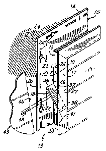
As shown in Fig. 2, the channel 10 includes a nail strip 15
with a siding abutment strip 16 extending away from the nail strip and a
cover strip 17 which extends from the abutment strip 16 parallel to the nail
strip 15. There are one or more tabs 18 which extend from the nail strip
15 along the abutment strip 16 to the cover strip 17. These tabs are
present only on vertical channels.
As shown more particularly in Fig. 2, the nail strip 15 which
is about 1.5 inches wide, includes a base side 20 which faces or contacts
the building wall 12 and an outer side 21 facing away from the building.
Likewise, there are a plurality of nail holes or slots 22 extending through
this nail strip 15 adapted to receive the shanks of nails 23. Nail strip 15
likewise includes tirst edge 24 which faces the siding and a second edge
,,
25. The abutment strip 16 typically extends about .75 inches at about a
90° angle out from the second edge 25 of the nail strip 15. It includes
an
inside surface 26, again being the side that faces the siding. The cover
strip 17 then extends about .75 inches away from the abutment strip 16 at
the upper edge 27 of the abutment strip 16.

-s-
Channel 10 includes one or more of tabs 18. Each tab
includes a first edge 36 which is bonded to the outer surface 21 of nail strip
15. The adjacent second edge 37 of tab 18 extends along the inside surface
26 of abutment strip 16. The third edge 38 of tab 18 is opposite the first
edge and is bonded to the inside surface 28 of cover strip 17. As shown,
cover strip 17 is about .25 inches wider than tab 18.
As shown in Fig. 2, the tab extends at an angle 41 down and
away from the nail strip 15. This angle should be from 20 to 70' and
preferably is about 45°. Obviously it must be less than 90°. The
channel
when installed is generally part of a vent, window, or other fixture. The
tab will be located on a vertical channel near a horizontal channel. For a
rectangular channel surrounding a vent, a tab is located within two inches
of a corner. For an octagonal vent, the tab is located on vertical sides.
For a door frame, a tab is located near the corners on the vertical channels.
Additional channels can be located along the vertical channels.
To install the channel of the present invention and siding
associated with the channel, the channel 10 is first nailed to the wall 12
with nails extending through the holes 22 in the nail strip I5. The siding
45 is then cut to size so that the inside edge 46 nearly abuts abutment strip
16. Thtis, the edge 46 will be covered by the cover strip 17. Where the
edge 46 would contact tab 18, a small horizontal slit 48 is cut through the
edge 46 to permit the tab to extend or intersect through the edge 46 into the
siding. Since cover strip 17 is wider than tab 18, it should conceal slit 48.

-6-
After installation of the siding, water will flow down the channel 10, along
tab 18, and to the outer side of the siding.
Fig. 3 shows an alternate embodiment of the present
invention. A tab 50 is formed as a small separate piece (referred to as a
flashing tab) having a small nail strip S1, a small abutment strip 52 and a
tab 53 running from the nail strip 51 along the abutment strip 52. A
small lip 54 extends vertically up from tab 53 opposite nail strip 55.
Flashing tab 50 can be used in combination with an existing
channel strip 55 by simply nailing flashing tab 50 in a channel 55 as the
channel is nailed to a wall. A plurality of these flashing tabs 50 would be
placed along the channel as desired. Alternately, flashing tab 50 can be
adhesively bonded to the nail strip 56 and abutment strip 57 of channel 55.
Again, these tab pieces 55 have the same benefit of the
primary embodiment of the present invention. Water tlowing down the
channel will run along tab 53 and is directed out of the channel by vertical
lip 54. In Fig. 3, the flashing tab for the left channel is shown. A mirror
image tab would be provided for the right channel (not shown).
The channel 10 of the present invention is formed by simply
injection molding the channel with the tab as part of the vent, fixture, or
frame piece. The present invention has, of course, utility in an elongated
channel which surrounds a door or a window in a house, such as that
shown in U.S. Patent 4,228,630. Further, the present invention can be
employed in the channel of a mounting block for a light fixture such as the
type disclosed in U.S. Patent 4,726,152. Further, it can be incorporated

into a siding channel used on exterior corners of buildings. A corner
channel, as shown as 20 in Fig. l, has two channels which share the same
abutment strip, but have separate opposed nailing strips and cover strips.
Tabs can be positioned in both channels of the corner channel providing the
same benefits of the present invention.
Also, this can be used in embodiments which do not include
a cover strip. In certain vents, the cover strip is separate from the
abutment strip and snaps in place. In such embodiments, the tab would be
fixed only to the nailing strip and the abutment strip and may include a
vertical lip such as lip 54 on tab 50. .
Thus, the present invention provides advantages for any
abutment channel used for lapped siding. In all of these embodiments, the
channel will act to direct water tlowing in the channel, away from the
house to the exterior side of the siding so that it can flow down the siding
and away from the house. This will protect the interior surface of the
house along with the siding itself.
This has been a description of the present invention along
with the preferred methods of practicing the present invention currently
known to the inventor. However, the invention itself should be defined
only by the appended claims wherein we claim:

Representative Drawing
A single figure which represents the drawing illustrating the invention.
Administrative Status

2024-08-01:As part of the Next Generation Patents (NGP) transition, the Canadian Patents Database (CPD) now contains a more detailed Event History, which replicates the Event Log of our new back-office solution.

Please note that "Inactive:" events refers to events no longer in use in our new back-office solution.

For a clearer understanding of the status of the application/patent presented on this page, the site Disclaimer , as well as the definitions for Patent , Event History , Maintenance Fee  and Payment History  should be consulted.

Event History

Description Date
Inactive: Reversal of expired status 2013-10-18
Time Limit for Reversal Expired 2013-09-10
Letter Sent 2012-09-10
Letter Sent 2011-04-18
Letter Sent 2011-03-21
Inactive: Single transfer 2011-03-07
Letter Sent 2008-10-15
Inactive: Office letter 2007-09-04
Letter Sent 2006-12-15
Inactive: Office letter 2006-11-23
Inactive: IPC from MCD 2006-03-11
Grant by Issuance 2002-10-29
Inactive: Cover page published 2002-10-28
Pre-grant 2002-08-09
Inactive: Final fee received 2002-08-09
Notice of Allowance is Issued 2002-02-13
Letter Sent 2002-02-13
Notice of Allowance is Issued 2002-02-13
Inactive: Approved for allowance (AFA) 2002-01-30
Amendment Received - Voluntary Amendment 2000-09-07
Inactive: Status info is complete as of Log entry date 2000-06-28
Letter Sent 2000-06-28
Inactive: Application prosecuted on TS as of Log entry date 2000-06-28
All Requirements for Examination Determined Compliant 2000-06-02
Request for Examination Requirements Determined Compliant 2000-06-02
Application Published (Open to Public Inspection) 1994-11-22

Abandonment History

There is no abandonment history.

Maintenance Fee

The last payment was received on 2002-08-08

Note : If the full payment has not been received on or before the date indicated, a further fee may be required which may be one of the following

  • the reinstatement fee;
  • the late payment fee; or
  • additional fee to reverse deemed expiry.

Patent fees are adjusted on the 1st of January every year. The amounts above are the current amounts if received by December 31 of the current year.
Please refer to the CIPO Patent Fees web page to see all current fee amounts.

Owners on Record

Note: Records showing the ownership history in alphabetical order.

Current Owners on Record
RICHWOOD BUILDING PRODUCTS, INC.
MASTIC HOME EXTERIORS, INC.
Past Owners on Record
MICHAEL VAGEDES
Past Owners that do not appear in the "Owners on Record" listing will appear in other documentation within the application.
Documents

To view selected files, please enter reCAPTCHA code :


To view images, click a link in the Document Description column. To download the documents, select one or more checkboxes in the first column and then click the "Download Selected in PDF format (Zip Archive)" or the "Download Selected as Single PDF" button.

List of published and non-published patent-specific documents on the CPD .

If you have any difficulty accessing content, you can call the Client Service Centre at 1-866-997-1936 or send them an e-mail at CIPO Client Service Centre.


Document
Description 
Date
(yyyy-mm-dd) 
Number of pages   Size of Image (KB) 
Claims 1995-04-07 3 54
Description 1995-04-07 7 185
Drawings 1995-04-07 1 44
Abstract 1995-04-07 1 14
Representative drawing 2002-01-29 1 19
Representative drawing 1998-08-24 1 8
Reminder - Request for Examination 2000-05-09 1 117
Acknowledgement of Request for Examination 2000-06-27 1 177
Commissioner's Notice - Application Found Allowable 2002-02-12 1 164
Courtesy - Certificate of registration (related document(s)) 2008-10-14 1 105
Courtesy - Certificate of registration (related document(s)) 2011-03-20 1 126
Courtesy - Certificate of registration (related document(s)) 2011-04-17 1 104
Maintenance Fee Notice 2012-10-21 1 171
Correspondence 2002-08-08 1 33
Correspondence 2006-10-09 2 14
Correspondence 2006-11-26 1 12
Correspondence 2007-09-03 1 16
Fees 2008-09-07 1 23
Correspondence 2011-03-20 1 22
Correspondence 2011-03-20 1 21
Fees 1996-08-21 1 63
Fees 1995-08-23 1 64