Language selection

Search

Patent 2105830 Summary

Third-party information liability

Some of the information on this Web page has been provided by external sources. The Government of Canada is not responsible for the accuracy, reliability or currency of the information supplied by external sources. Users wishing to rely upon this information should consult directly with the source of the information. Content provided by external sources is not subject to official languages, privacy and accessibility requirements.

Claims and Abstract availability

Any discrepancies in the text and image of the Claims and Abstract are due to differing posting times. Text of the Claims and Abstract are posted:

  • At the time the application is open to public inspection;
  • At the time of issue of the patent (grant).
(12) Patent: (11) CA 2105830
(54) English Title: GOLF CLUB HEAD WITH WEIGHT PAD
(54) French Title: TETE DE BATON DE GOLF A MASSE D'EQUILIBRAGE INTERNE
Status: Term Expired - Post Grant Beyond Limit
Bibliographic Data
(51) International Patent Classification (IPC):
  • A63B 53/04 (2015.01)
(72) Inventors :
  • SOLHEIM, KARSTEN (United States of America)
(73) Owners :
  • KARSTEN MANUFACTURING CORPORATION
(71) Applicants :
  • KARSTEN MANUFACTURING CORPORATION (United States of America)
(74) Agent: SMART & BIGGAR LP
(74) Associate agent:
(45) Issued: 1997-03-18
(22) Filed Date: 1993-09-09
(41) Open to Public Inspection: 1994-09-18
Examination requested: 1993-10-07
Availability of licence: N/A
Dedicated to the Public: N/A
(25) Language of filing: English

Patent Cooperation Treaty (PCT): No

(30) Application Priority Data:
Application No. Country/Territory Date
08/032,304 (United States of America) 1993-03-17

Abstracts

English Abstract

A golf club head made of a suitable metal such as stainless steel includes a hollow body and a hosel. The hollow body has a top wall, a bottom wall, a side wall, and a front wall with a face arranged for impacting golf balls. The hollow body has a weight pad which provides the golf club head with increased resistance to rotation or twisting upon impact with golf balls at off-center points on the face. The weight pad weighs between 5 and 15 grams and is located in the heel portion of the body. The weight pad is elongated in a direction extending along a length dimension of the body side wall.


French Abstract

Une tête de bâton de golf faite d'un métal adapté tel que l'acier inoxydable comprend un corps creux et un hosel. Le corps creux présente une paroi supérieure, une paroi inférieure, une paroi latérale et une paroi avant avec une face prévue pour frapper des balles de golf. Le corps creux est doté d'une masse d'équilibrage qui offre à la tête de bâton de golf une résistance accrue à la rotation ou à la torsion suite à l'impact avec les balles de golf à des points décentrés points sur la face. La masse d'équilibrage pèse entre 5 et 15 grammes et est située dans la partie talon du corps. La masse d'équilibrage est allongée dans une direction s'étendant le long d'une dimension de longueur de la paroi latérale du corps.

Claims

Note: Claims are shown in the official language in which they were submitted.

What is claimed is:
1. A golf club head having a center of gravity, said
golf club head comprising:
a hollow body having a heel portion, a toe portion, a
top wall, a bottom wall, a side wall between said top and
bottom walls, a front wall with a face for impacting a golf
ball;
a hosel for receiving one end of an elongated shaft;
said face having a sweet spot thereon aligned with the
center of gravity so that when a golf ball is impacted at
said sweet spot no rotation of the club head will occur, said
face being disposed forwardly of and inclined with respect to
a first vertical plane containing a longitudinal axis of the
elongated shaft, said face intersecting and being
substantially perpendicular to a second vertical plane
containing the center of gravity, said second vertical plane
dividing said body into said heel and toe portions; and
a weight pad disposed along said side wall in the heel
portion of the body rearwardly of said first vertical plane
and intermediate said hosel and said second vertical plane,
said weight pad providing the golf club head with increased
resistance to horizontal rotation about a vertical axis that
extends through the center of gravity when the club head
impacts a golf ball on the face at off-center points spaced
laterally of the sweet spot.

2. The golf club head of claim 1, wherein said weight
pad weighs between 5 and 15 grams.
3. The golf club head of claim 1, wherein said hollow
body is formed of metal.
4. The golf club head of claim 3, wherein said hollow
body is formed of stainless steel.
5. The golf club head of claim 1, wherein said weight
pad comprises a single weight disposed only in the heel
portion of the body.
6. The golf club head of claim 5, wherein said side
wall has a length dimension extending between said front wall
and said hosel, and wherein said weight pad is elongated in a
direction extending along the length dimension of said side
wall.
7. The golf club head of claim 6, wherein said weight
pad is divided into two substantially equal parts by a
vertical plane which intersects the first and second vertical
planes at approximately 45 degrees.
8. The golf club head of claim 6, wherein said first,
second and third planes intersect at a common axis.
9. The golf club head of claim 1, wherein said top,
bottom and side walls each have a thickness between 0.036 and
- 8 -

0.040 inch, and wherein said front wall has a thickness
between 0.128 and 0.135 inch.
10. A golf club head having a center of gravity, said
golf club head comprising:
a hollow body having a heel portion, a toe portion,
a top wall, a bottom wall, a side wall between said top and
bottom walls, a front wall with a face for impacting a golf
ball;
a hosel for receiving one end of an elongated shaft;
said face having a sweet spot thereon aligned with
the center of gravity so that when a golf ball is impacted at
said sweet spot no rotation of the club head will occur, said
face being disposed forwardly of an inclined with respect to a
first vertical plane containing a longitudinal axis of the
elongated shaft, said face intersecting and being
substantially perpendicular to a second vertical plane
containing the center of gravity, said second vertical plane
dividing said body into said heel and toe portions;
a weight pad disposed along said side wall in the
heel portion of the body rearwardly of said first vertical
plane and intermediate said hosel and said second vertical
plane, said weight pad providing the golf club head with
increased resistance to horizontal rotation about a vertical
axis that extends through the center of gravity when the club
head impacts a golf ball on the face at off-center points
spaced laterally of the sweet spot;
said side wall having a length dimension measured
between said first vertical plane and a third vertical plane
- 9 -

which is disposed generally parallel to said first vertical
plane while being located rearwardly of both said front wall
and said hosel, said third vertical plane containing a
rearwardmost point on said side wall, said weight pad being
elongated in a direction extending along the length dimension
of said side wall; and
said weight pad being divided into two substantially
equal parts by a fourth vertical plane which intersects the
first and second vertical planes at approximately 45 degrees.
11. The golf club head of claim 10, wherein said weight
pad weighs between 5 and 15 grams.
12. The golf club head of claim 10, wherein said hollow
body is formed of metal.
13. The golf club head of claim 12, wherein said hollow
body is formed of stainless steel.
14. The golf club head of claim 10, wherein said first,
second and fourth vertical planes intersect at a common axis.
15. The golf club head of claim 10, wherein said top,
bottom and side walls each have a thickness between 0.036 and
0.040 inch, and wherein said front wall has a thickness
between 0.128 an 0.135 inch.
- 10 -

Description

Note: Descriptions are shown in the official language in which they were submitted.


2 1 0 5 8 3 0
KMC- 2 6 3
GO~F CLUB HEAD WITH WEIGHT PAD
BACKGROUND OF THE INVENTION
This invention relates generally to golf clubs and, in
particular, to a golf club head with a weight pad for
increasing resistance to rotation or twisting of the golf
club head on off-center impacts with golf balls.
Golf clubs known as "woods" traditionally have a head
made of a suitable wooden material such as maple or persimmon
attached to one end of an elongated shaft. These wooden club
heads are usually solid and are shaped with their weight
properly distributed about their center of gravity to
maximize performance. Golf club "wood" heads have also been
formed of suitable metals such as stainless steel. Metal
heads are usually hollow. Various attempts have been made to
distribute weight in metal heads with respect to their center
of gravity so that performance is maximized. Such attempts
have included placing different types and numbers of weight
members at different locations inside the metal heads.
Examples of such attempts are disclosed in prior~U.S. Patent
Nos. 1,167,106 to Palmer; 1,526,438 to Scott; 1,S82,836 to
Link; 5,058,895 to Igarashi; and 5,141,230 to Antonious. In
the Palmer, Scott and Link patents, weight members are
located directly behind the center of gravity of the club

21 05830
head. In the Igarashi and Antonious patents, weight members
are located in heel and toe portions of the club heads.
SUMMAR~ OF THE INVENTION
The present lnvention provldes a golf club head
having a center of gravity, said golf club head comprising: a
hollow body having a heel portlon, a toe portlon, a top wall,
a bottom wall, a side wall between said top and bottom walls,
a front wall with a face for impacting a golf ball; a hosel
for receiving one end of an elongated shaft; said face having
a sweet spot thereon aligned with the center of gravity so
that when a golf ball is impacted at said sweet spot no
rotation of the club head wlll occur, sald face belng disposed
forwardly of and inclined with respect to a first vertical
plane containing a longitudinal axis of the elongated shaft,
said face intersecting and being substantially perpendlcular
to a second vertlcal plane contalnlng the center of gravlty,
said second vertical plane dividing said body into sald heel
and toe portlons; and a welght pad dlsposed along sald side
wall ln the heel portion of the body rearwardly of sald flrst
vertical plane and intermediate said hosel and sald second
vertical plane, said weight pad providing the golf club head
with increased resistance to horizontal rotation about a
vertlcal axls that extends through the center of gravlty when
the club head impacts a golf ball on the face at off-center
points spaced laterally of the sweet spot.
In the preferred embodiment of the golf club head,
the body side wall has a length dimension measured between the
first vertical plane and a third vertical plane whlch ls
disposed generally parallel to the first vertical plane while
-- 2
68319-36

2 1 05830
belng located rearwardly of both the front wall and the hosel,
and the welght pad has an elongate shape ln a directlon
extendlng along the length dlmenslon of the slde wall.
Preferably the welght pad welghs between 5 and 15
grams, and ls dlvlded lnto two substantlally equal parts by a
fourth vertlcal plane whlch lntersects the flrst and second
vertlcal planes at approxlmately 45 degrees. The flrst,
second and fourth vertlcal planes lntersect at a common axls.
DESCRIPTION OF THE DRAWINGS
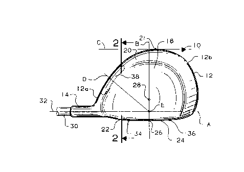
Flg. 1 ls a bottom vlew of a golf club head havlng a
welght pad accordlng to the present lnventlon;
Flg. 2 ls an enlarged sectlonal vlew taken along
llnes 2-2 ln Flg. l; and
Flg. 3 ls a rear elevatlonal vlew of the golf club
head shown ln Flg. 1.
DESCRIPTION OF THE PREFERRED EMBODIMENT
Referrlng to Flg. 1, a golf club head 10 lncludes a
hollow body 12 and a hosel 14 preferably formed of a sultable
metal such as stalnless steel. The body 12 has a heel portlon
12a, a toe portlon 12b, a top wall 16, a bottom wall 18, a
slde wall 20 between the top and bottom walls 16 and 18, and a
front wall 22 havlng a face 24 arranged for contactlng a golf
ball. Located on the face 24 ls a generally central polnt 26
known as a "sweet spot" whlch ls allgned wlth a club head
center of gravlty 28. When the face 24 lmpacts a golf ball at
the sweet spot 26, no rotatlon or twlstlng of the club head 10
wlll occur. One end of an elongated shaft 30 ls recelved ln
the hosel 14.
The club head face 24 ls dlsposed forwardly of and
-- 3
68319-36

2 1 05830
incllned wlth respect to a flrst vertlcal plane A whlch
contalns the longltudlnal axls 32 of the shaft 30. The face
24 lntersects and ls substantlally perpendlcular to a second
vertlcal plane B whlch contalns the sweet spot 26 and the
center of gravlty 28. The vertlcal plane B dlvldes the body
12 lnto the heel and toe portlons 12a, 12b. The slde wall 20
of the body 12 has a length dlmenslon measured between the
flrst vertlcal plane A and a thlrd vertlcal plane C whlch ls
generally parallel to the vertlcal plane A whlle belng located
rearwardly of both the hosel 14 and the front wall 22. The
vertlcal plane C contalns a rearwardmost polnt 21 on the side
wall 20.
The body 12 has a generally teardrop shape with a
large percentage of its weight located in the toe portion 12b
thereof and a small percentage of its welght located in the
heel portion 12a thereof. The teardrop shape of the body 12
makes the club head 10 very aerodynamic on a golfer's
downswlng. Upon lmpact wlth a golf ball at any off-center
points (such as points 34, 36) on the face 24 spaced laterally
of the sweet spot 26, the extra welght ln the body toe portion
12b increases horlzontal rotatlon or twlstlng of the club head
10 (ln elther a clockwlse dlrectlon or ln a counterclockwlse
dlrectlon when vlewed ln Flg. 1) about a vertlcal axls that
extends through the center of gravlty 28. For example, upon
lmpact at the off-center point 34, the horlzontal club head
rotatlon causes the face 24 to close whlch results in a fade
type spin on the golf ball. Upon impact at the off-center
polnt 36, the horlzontal club head rotatlon or twlstlng causes
the face 24 to open whlch results ln a hook type spln on the
-- 4
68319-36

21 05830
golf ball.
It has been determlned that a properly located
weight member wlll provlde the golf club head 10 wlth
lncreased reslstance to horlzontal rotatlon or twlstlng upon
off-center lmpacts wlth golf balls. Thls lncreased reslstance
to horlzontal rotatlon or twlstlng of the club head 10 results
ln less fade type spln and less hook type spln on golf balls
whlch are lmpacted at off-center polnts on the face 24.
Accordlngly, a welght pad 38 ls formed generally along the
lnslde of the body side wall 20 ln the heel portlon 12a of the
body 12. The welght pad 38 ls located rearwardly of the flrst
vertlcal plane A and lntermedlate the hosel 14 and the second
vertlcal plane B. The welght pad 38, whlch preferably welghs
between S and 15 grams, ls arranged so that lt ls dlvlded lnto
two substantlally equal parts by a fourth vertlcal plane D
that lntersects the vertlcal planes A and B at approxlmately
45 degrees. The flrst, second and fourth vertlcal planes A, B
and D lntersect at common axls E.
Durlng testlng of the club head 10, the welght pad
38
68319-36
,~

2 1 05830
was located in three different locations inside the body 12
along the length dimension of the side wall 20. A first test
location for the weight pad 38 was along the side wall 20 in
the body toe portion 12b. This first test location created
more fade type spin and more hook type spin on golf balls on
off-center impacts by causing the club head face 24 to open
and close farther. In other words, golf balls deviated
farther from their intended path of travel when the weight
pad 38 was located in the toe portion 12b. A second test
location for the weight pad 38 was directly behind the sweet
spot 26 and the center of gravity 28. This second test
location had no effect on the fade type spin and the hook
type spin on golf balls. That is, with the weight pad 38
located directly behind the center of gravity, golf balls
travelled along the same path as when the weight pad 38 is
eliminated from the club head 10. A third test location for
the weight pad 38 was along the side wall 20 in the body heel
portion 12a. This third test location created less fade spin
and less hook spin on golf balls by resisting opening and
closing of the face 24 on off-center impacts with golf balls.
Therefore, golf balls travel closer to their intended path
when the weight pad 38 is located as shown in Figs. 1-3.
It will be understood that the top, bottom and side
walls 16, 18 and 20 each have a thickness between 0.036 and
0.040 inch. The front wall 22 has a thickness between 0.128
and 0.135 inch.

Representative Drawing
A single figure which represents the drawing illustrating the invention.
Administrative Status

2024-08-01:As part of the Next Generation Patents (NGP) transition, the Canadian Patents Database (CPD) now contains a more detailed Event History, which replicates the Event Log of our new back-office solution.

Please note that "Inactive:" events refers to events no longer in use in our new back-office solution.

For a clearer understanding of the status of the application/patent presented on this page, the site Disclaimer , as well as the definitions for Patent , Event History , Maintenance Fee  and Payment History  should be consulted.

Event History

Description Date
Inactive: IPC deactivated 2017-09-16
Inactive: First IPC assigned 2016-07-12
Inactive: IPC assigned 2016-07-12
Inactive: IPC expired 2015-01-01
Inactive: Expired (new Act pat) 2013-09-09
Grant by Issuance 1997-03-18
Application Published (Open to Public Inspection) 1994-09-18
All Requirements for Examination Determined Compliant 1993-10-07
Request for Examination Requirements Determined Compliant 1993-10-07

Abandonment History

There is no abandonment history.

Fee History

Fee Type Anniversary Year Due Date Paid Date
MF (patent, 4th anniv.) - standard 1997-09-09 1997-08-25
MF (patent, 5th anniv.) - standard 1998-09-09 1998-08-24
MF (patent, 6th anniv.) - standard 1999-09-09 1999-08-11
MF (patent, 7th anniv.) - standard 2000-09-11 2000-08-09
MF (patent, 8th anniv.) - standard 2001-09-10 2001-08-15
MF (patent, 9th anniv.) - standard 2002-09-09 2002-08-14
MF (patent, 10th anniv.) - standard 2003-09-09 2003-08-13
MF (patent, 11th anniv.) - standard 2004-09-09 2004-08-16
MF (patent, 12th anniv.) - standard 2005-09-09 2005-08-19
MF (patent, 13th anniv.) - standard 2006-09-11 2006-08-17
MF (patent, 14th anniv.) - standard 2007-09-10 2007-08-17
MF (patent, 15th anniv.) - standard 2008-09-09 2008-08-18
MF (patent, 16th anniv.) - standard 2009-09-09 2009-08-19
MF (patent, 17th anniv.) - standard 2010-09-09 2010-08-17
MF (patent, 18th anniv.) - standard 2011-09-09 2011-08-17
MF (patent, 19th anniv.) - standard 2012-09-10 2012-08-17
Owners on Record

Note: Records showing the ownership history in alphabetical order.

Current Owners on Record
KARSTEN MANUFACTURING CORPORATION
Past Owners on Record
KARSTEN SOLHEIM
Past Owners that do not appear in the "Owners on Record" listing will appear in other documentation within the application.
Documents

To view selected files, please enter reCAPTCHA code :


To view images, click a link in the Document Description column. To download the documents, select one or more checkboxes in the first column and then click the "Download Selected in PDF format (Zip Archive)" or the "Download Selected as Single PDF" button.

List of published and non-published patent-specific documents on the CPD .

If you have any difficulty accessing content, you can call the Client Service Centre at 1-866-997-1936 or send them an e-mail at CIPO Client Service Centre.


Document
Description 
Date
(yyyy-mm-dd) 
Number of pages   Size of Image (KB) 
Cover Page 1995-06-10 1 51
Abstract 1995-06-10 1 44
Claims 1995-06-10 3 116
Description 1995-06-10 6 297
Drawings 1995-06-10 1 40
Claims 1997-02-26 4 133
Cover Page 1997-02-26 1 13
Drawings 1997-02-26 1 28
Description 1997-02-26 6 231
Abstract 1997-02-26 1 18
Representative drawing 1998-08-12 1 9
Fees 1996-08-23 1 85
Fees 1995-08-18 1 86
Examiner Requisition 1996-07-26 2 56
Prosecution correspondence 1996-09-23 3 126
PCT Correspondence 1997-01-06 1 29
Prosecution correspondence 1993-10-07 1 25
Courtesy - Office Letter 1994-04-07 1 32