Language selection

Search

Patent 2106148 Summary

Third-party information liability

Some of the information on this Web page has been provided by external sources. The Government of Canada is not responsible for the accuracy, reliability or currency of the information supplied by external sources. Users wishing to rely upon this information should consult directly with the source of the information. Content provided by external sources is not subject to official languages, privacy and accessibility requirements.

Claims and Abstract availability

Any discrepancies in the text and image of the Claims and Abstract are due to differing posting times. Text of the Claims and Abstract are posted:

  • At the time the application is open to public inspection;
  • At the time of issue of the patent (grant).
(12) Patent: (11) CA 2106148
(54) English Title: DEVICE FOR RESAFING AN ARMED MINE
(54) French Title: DISPOSITIF POUR REMETTRE EN OEUVRE LES DISPOSITIFS DE SECURITE D'UNE MINE ARMEE
Status: Expired and beyond the Period of Reversal
Bibliographic Data
(51) International Patent Classification (IPC):
  • F42B 33/06 (2006.01)
  • F42B 23/00 (2006.01)
  • F42C 15/44 (2006.01)
(72) Inventors :
  • BJELVERT, SVEN (Sweden)
(73) Owners :
  • SAAB AB
  • BOFORS AB
(71) Applicants :
  • SAAB AB (Sweden)
  • BOFORS AB (Sweden)
(74) Agent: SMART & BIGGAR LP
(74) Associate agent:
(45) Issued: 2004-11-02
(22) Filed Date: 1993-09-14
(41) Open to Public Inspection: 1994-04-03
Examination requested: 2000-07-14
Availability of licence: N/A
Dedicated to the Public: N/A
(25) Language of filing: English

Patent Cooperation Treaty (PCT): No

(30) Application Priority Data:
Application No. Country/Territory Date
9202869-5 (Sweden) 1992-10-02

Abstracts

English Abstract


A device for resafing an armed mine (3). The device
comprises a resafing means (2) for performing a resafing
movement in the mine, an electric motor (1) for providing
said resafing movement, and a battery (5) for powering the
electric motor. An artificial load (8) is connected across
the battery (5) and is by means of a timer circuit (4)
intermittently transformable from a normally non-conductive
state to a conductive state. The artificial load is
dimensioned to draw, in its conductive state, substantially as
high electric current from the battery as the electric
motor (1) draws during the resafing movement. A comparator
(12) is provided to compare the battery voltage to a
reference voltage (Vref), and to deliver a resafing signal to
the electric motor when the battery voltage falls below
the reference voltage in order to initiate the resafing
movement.


Claims

Note: Claims are shown in the official language in which they were submitted.

6
CLAIMS:
1. A device for resafing an armed mine, including a
resafing means for performing a resafing movement of a
safety, arming and fuze unit in the mine, an electric motor
operatively connected to the resafing means to cause said
resafing movement, and a battery for powering the electric
motor, further comprising an artificial load connectable
across the battery, the artificial load being dimensioned to
be able to draw substantially as high electric current from
the battery as the electric motor draws during said resafing
movement, and by a comparator able to compare the battery
voltage to a reference voltage when the artificial load is
connected across the battery, and able to deliver a resafing
signal to the electric motor if the battery voltage has
dropped below the reference voltage, in order to initiate
said resafing movement.
2. A device in accordance with Claim 1, wherein the
artificial load is normally non-conductive, and a timer
circuit is provided to intermittently deliver to the
artificial load a control signal, which during its duration
transforms the artificial load to a conductive state.
3. A device in accordance with Claim 2, further
comprising an electronic OR-circuit, one input terminal of
which is connected to the timer circuit in order to receive
an alternative resafing signal after a predetermined lay-
time, and the other input terminal of which is connected to
the output terminal of the comparator.

Description

Note: Descriptions are shown in the official language in which they were submitted.


t_ ..r
1
21061~~
TECHNICAL FIELD
The present invention relates to a device for resafing an
armed mine. The invention relates particularly, but not
exclusively, to a device for resafing an armed land mine.
BACKGROUND PRIOR ART
Land mines nearly always utilize a safe mechanism to pro-
vide a delayed arming function. Arming is initiated by
starting a timer mechanism or a battery-operated electric
motor which drives a gearing device during a predeter-
mined time interval whereupon arming will occur. During
this time interval all personnel have to leave the danger
zone of the mine.
The mine will then be armed during a certain preset time
period, whereafter a resafing shall be performed. By means
of a spring-biassed arming means (operated by a timer)
which co-operates with a rotor element within a detonator
house, a resafing may readily be performed by releasing a
locking device.
When performing the resafing by electronic means, the mine
often utilizes a so called reservoir capacitor which is
able to, during a short time, deliver a higher electric
current than can be delivered by the conventional mine
battery. The energy of such a reservoir capacitor can, at
an appropriate time, be fed to the powder fuze of a gas
generator. A piston of the gas generator will then release
the rotor element such that this will be returned to a
fully safed condition, thereby accomplishing a resafing.
In those cases where the safety, arming and fuze functions
are powered by an electric motor there will be required
so large quantity of energy that such a reservoir capaci-
tor will in practice not be able to store sufficient
energy. Therefore, the battery itself has to deliver the

CA 02106148 2004-03-08
75819-1
2
current to the electric motor. When utilizing a fresh
battery when burying the mine and a lay-time which is not
too long, there will always be enough energy in the battery
to provide a resafing.
The difficulties will of course increase if the
battery has to be stored during a long time, and if great
length of operation time is desired for the mine.
The mine fuze is often provided with a battery
guard. The aim of the guard is to shut off the electronic
means if the battery voltage has fallen so much that the
normal function of the mine may be jeopardized. Preferably,
the mine should also be resafed in order to avoid it from
becoming a so called dud.
Since the electric motor draws 10 or 100 times
more current than the rest of the electronic means, it will
be understood that when the battery guard will sense a
voltage drop such that it will switch on the motor, the load
will be so heavy that the battery voltage will fall to a
level where the motor is unable to function.
DISCLOSURE OF THE INVENTION
The object of the invention is to provide a device
of the kind mentioned by way of introduction, which will
guarantee automatic resafing of the mine before the battery
voltage has fallen below a critical reference voltage level.
According to the invention there is provided a
device for resafing an armed mine, including a resafing
means for performing a resafing movement of a safety, arming
and fuze unit in the mine, an electric motor operatively
connected to the resafing means to cause said resafing
movement, and a battery for powering the electric motor,

CA 02106148 2004-03-08
75819-1
2a
further comprising an artificial load connectable across the
battery, the artificial load being dimensioned to be able to
draw substantially as high electric current from the battery
as the electric motor draws during said resafing movement,
and by a comparator able to compare the battery voltage to a
reference voltage when the artificial load is connected
across the battery, and able to deliver a resafing signal to
the electric motor if the battery voltage has dropped below
the reference voltage, in order to initiate said resafing
movement.

3
21os1~g
BRIEF DESCRIPTION OF THE DRAWING
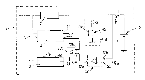
The sole figure of the drawing illustrates an electric
circuit diagram of a device according to the invention.
PREFERRED EMBODIMENT
The figure illustrates electric motor 1 which is operati-
vely connected to a movable resafing means in the form of
slider 2 able to perform a resafing movement of a conven-
tional, and therefore not shown Safety, Arming and Fuze
Unit (so called SAFU) in only schematically shown land
mine 3.
The mine is, in a conventional way, provided with timer
circuit 4, which, in a known way, has output terminal 4a
able to deliver an arming signal, after a predetermined
time interval elapses, to first input terminal la of mo-
tor 1 in order to start arming of the mine. Timer circuit
4 has also output terminal 4b, which after a certain lay-
time, for instance 60 days, emits a resafing signal to
second input terminal lb of motor 1 in order to start re-
safing of the mine.
Electric motor 1 and timer circuit 4 are powered by elec-
trio battery 5 which is able to be connected and discon-
nected, respectively, by switch handle 6. The voltage of
timer circuit 4 is stabilized by DC/DC converter 7. Other
components of the mine, which are supplied with current
from battery 5 are not shown, since they do not constitute
any part of the invention.
According to the invention artificial load 8 is connected
in parallel with battery 5. Artificial load 8 comprises,
in the embodiment shown, a series arrangement of resis-
tance 9 and normally non-conductive field effect transis-
tor 10. Transistor 10 is connected with its gate l0a to

4 210018
third output terminal 4c of timer circuit 4. Timex circuit
4 is arranged to intermittently, for instance twice a day,
emit at its output terminal 4c a control signal to gate
10a of the transistor in order to transform transistor 10
to a conductive condition during the duration of the con
trol signal, which may be 2 to 4 sec., for instance.
Artificial load 8 is dimensioned to draw substantially as
high electric current from battery 5 as electric motor 1
draws during its resafing movement. Each time artificial
load 8 becomes conductive, the terminal voltage of battery
5 will, accordingly, drop. This terminal voltage is, via
lead 11, supplied to first input terminal 12a of voltage
comparator 12, second input terminal 12b of which is con-
netted to reference voltage Vref.
Output terminal 12c of comparator 12, and output terminal
4b of the timer circuit are connected to respective input
terminal 13a and 13b, respectively, of logical OR-circuit
13, output terminal 13c of which is connected to input
terminal lb of the electric motor.
Accordingly, resafing of the mine will be automatically
performed, when a connection of artificial load 8 will
reduce the terminal voltage of battery 5 to a value below
Vref, since input terminal 13a of the OR-circuit is high
due to signal from comparator 12. However, i,f the terminal
voltage of battery 5 never drops below Vref during the
lay-time of the mine, the mine will be resafed only after
the lay-time has elapsed, since second input terminal 13b
of the OR-circuit then is high due to signal from timer
circuit 4.
Battery 5 is suitably a lithium battery, since that kind
of battery will function within a large temperature range
(-35°C to 65°C). Battery 5 is typically a lithium thronyle
chloride cell (LiSOCI2) in the range of R-14 having the

5
following typical data
~10~148
-terminal voltage 3.65 volts
-capacity 5 amperehours
-output voltage at 1 milliampere, 10°C 3.6 volts
100 milliamperes, 20°C 3.4 volts
1 milliampere, -40°C 3.3 volts
100 milliamperes, -40°C 2.7 volts
If the cell will be charged by 1 milliampere during a long
time at room temperature, the voltage will gradually de-
crease. If the reference voltage of comparator 12 is set
at 2.5 volts, the battery cell will then in all probabili-
ty be exhausted. However, by testing the cell intermit-
tently according to the invention, automatic resafing will
be guaranteed before the battery voltage, subjected to low
charge, has dropped below 2.5 volts. Hence, correct opera-
tion of the mine will always be obtained.

Representative Drawing
A single figure which represents the drawing illustrating the invention.
Administrative Status

2024-08-01:As part of the Next Generation Patents (NGP) transition, the Canadian Patents Database (CPD) now contains a more detailed Event History, which replicates the Event Log of our new back-office solution.

Please note that "Inactive:" events refers to events no longer in use in our new back-office solution.

For a clearer understanding of the status of the application/patent presented on this page, the site Disclaimer , as well as the definitions for Patent , Event History , Maintenance Fee  and Payment History  should be consulted.

Event History

Description Date
Time Limit for Reversal Expired 2008-09-15
Letter Sent 2007-09-14
Inactive: IPC from MCD 2006-03-11
Grant by Issuance 2004-11-02
Inactive: Cover page published 2004-11-01
Letter Sent 2004-08-17
Inactive: Final fee received 2004-07-26
Pre-grant 2004-07-26
Inactive: Single transfer 2004-07-22
Notice of Allowance is Issued 2004-04-28
Letter Sent 2004-04-28
Inactive: Approved for allowance (AFA) 2004-04-15
Amendment Received - Voluntary Amendment 2004-03-08
Inactive: S.30(2) Rules - Examiner requisition 2003-09-08
Amendment Received - Voluntary Amendment 2000-09-28
Inactive: Application prosecuted on TS as of Log entry date 2000-08-03
Letter Sent 2000-08-03
Inactive: Status info is complete as of Log entry date 2000-08-03
All Requirements for Examination Determined Compliant 2000-07-14
Request for Examination Requirements Determined Compliant 2000-07-14
Application Published (Open to Public Inspection) 1994-04-03

Abandonment History

There is no abandonment history.

Maintenance Fee

The last payment was received on 2004-08-05

Note : If the full payment has not been received on or before the date indicated, a further fee may be required which may be one of the following

  • the reinstatement fee;
  • the late payment fee; or
  • additional fee to reverse deemed expiry.

Please refer to the CIPO Patent Fees web page to see all current fee amounts.

Owners on Record

Note: Records showing the ownership history in alphabetical order.

Current Owners on Record
SAAB AB
BOFORS AB
Past Owners on Record
SVEN BJELVERT
Past Owners that do not appear in the "Owners on Record" listing will appear in other documentation within the application.
Documents

To view selected files, please enter reCAPTCHA code :


To view images, click a link in the Document Description column. To download the documents, select one or more checkboxes in the first column and then click the "Download Selected in PDF format (Zip Archive)" or the "Download Selected as Single PDF" button.

List of published and non-published patent-specific documents on the CPD .

If you have any difficulty accessing content, you can call the Client Service Centre at 1-866-997-1936 or send them an e-mail at CIPO Client Service Centre.


Document
Description 
Date
(yyyy-mm-dd) 
Number of pages   Size of Image (KB) 
Representative drawing 1999-07-12 1 7
Description 1994-05-25 5 184
Cover Page 1994-05-25 1 17
Claims 1994-05-25 1 42
Claims 2004-03-08 1 36
Representative drawing 2004-03-15 1 8
Drawings 1994-05-25 1 10
Abstract 1994-05-25 1 19
Description 2004-03-08 6 175
Cover Page 2004-09-29 1 39
Reminder - Request for Examination 2000-05-16 1 117
Acknowledgement of Request for Examination 2000-08-03 1 177
Commissioner's Notice - Application Found Allowable 2004-04-28 1 161
Courtesy - Certificate of registration (related document(s)) 2004-08-17 1 105
Maintenance Fee Notice 2007-10-29 1 171
Fees 2003-08-14 1 37
Correspondence 2004-07-26 1 33
Fees 1996-08-15 1 42
Fees 1995-08-16 1 46