Language selection

Search

Patent 2106149 Summary

Third-party information liability

Some of the information on this Web page has been provided by external sources. The Government of Canada is not responsible for the accuracy, reliability or currency of the information supplied by external sources. Users wishing to rely upon this information should consult directly with the source of the information. Content provided by external sources is not subject to official languages, privacy and accessibility requirements.

Claims and Abstract availability

Any discrepancies in the text and image of the Claims and Abstract are due to differing posting times. Text of the Claims and Abstract are posted:

  • At the time the application is open to public inspection;
  • At the time of issue of the patent (grant).
(12) Patent: (11) CA 2106149
(54) English Title: APPARATUS AND METHOD FOR POSITIONING A LINK
(54) French Title: DISPOSITIF ET METHODE POUR POSITIONNER UN MAILLON
Status: Expired and beyond the Period of Reversal
Bibliographic Data
(51) International Patent Classification (IPC):
  • F16C 7/06 (2006.01)
  • B60G 7/00 (2006.01)
  • F16C 23/10 (2006.01)
(72) Inventors :
  • SCHARTMAN, DANIEL J. (United States of America)
  • BALZER, DAVID J. (United States of America)
(73) Owners :
  • CATERPILLAR INC.
(71) Applicants :
  • CATERPILLAR INC. (United States of America)
(74) Agent: SMART & BIGGAR LP
(74) Associate agent:
(45) Issued: 2004-05-11
(22) Filed Date: 1993-09-14
(41) Open to Public Inspection: 1994-04-06
Examination requested: 2000-08-11
Availability of licence: N/A
Dedicated to the Public: N/A
(25) Language of filing: English

Patent Cooperation Treaty (PCT): No

(30) Application Priority Data:
Application No. Country/Territory Date
7/956,208 (United States of America) 1992-10-05

Abstracts

English Abstract


Links are useful for supporting and
positioning spaced apart housing relative to each
other. To allow for tolerance stackup the length of
the link needs to be adjustable and still be strong
enough to withstand high forces. The subject
adjustable link includes a first end portion removably
attached to a axle structure and a second end portion
attached to a ripper structure. The second end
portion includes an eccentric cam which is rotatable
to adjust the length of the link. When the cam is
properly adjusted it is moved into contact with a
locking plate on the ripper structure to prevent
rotation. A spacer washer is positioned between the
cam and the ripper structure to prevent disengagement
of the cam from the ripper structure. This
arrangement of components provides for adjusting the
length of a link and provides a locking structure
which will withstand the high forces in the structure.


Claims

Note: Claims are shown in the official language in which they were submitted.

-6-
Claims
1. A length adjustment apparatus,
comprising:
a first structure;
a second structure spaced from the first
structure;
an elongated link having a first end portion
removably connected to the first structure and a
second end portion removably connected to the second
structure, the second end portion includes a mounting
hole;
an eccentric cam rotatably mounted within
the mounting hole of the link and including a locking
flange having a plurality of lobes on an outer
periphery and an adjustment portion axially offset
from the locking flange, a hole extends through the
locking flange and the adjustment portion; and
a locking plate welded to the second
structure, and including an end surface hawing a
plurality of lobes interacting with the plurality of
lobes on the locking flange to prevent rotation of the
cam.
2. The length adjustment apparatus of claim
1, wherein the second structure includes spaced first
and second mounting brackets having aligned holes
therein.
3. The length adjusting apparatus of claim
2, wherein the locking plate is welded to the first
mounting bracket and a spacer washer having a central
hole defined therein is positioned between the
adjustment portion and the second mounting bracket.

-7-
4. The length adjusting apparatus of claim
3 includes a pin which passes through the holes in the
first and second mounting brackets, the cam and the
spacer washer for attaching the second end portion of
the link to the second structure.
5. A method for positioning a link
comprising the steps of:
attaching a first end portion of the link to
a first structure;
aligning a second end portion of the link
with spaced mounting holes in a second structure;
rotating an eccentric cam within the second
end portion of the link aligning a mounting hole in
the cam with the mounting holes in the second
structure;
moping the eccentric cam sideways into
engagement with a locking plate on the second
structure;
positioning a spacer washer between the
link and the second structure to prevent disengagement
of the cam from the locking plate; and
inserting a pin through the mounting holes
of the structure, the cam and the spacer washer.

Description

Note: Descriptions are shown in the official language in which they were submitted.


21~~149
Description
An Apparatus end Method For Positionina A Lynx
Technical Field
This invention relates generally to a link
connectable between two spaced structures and more
particularly to an arrangement for adjusting and
maintaining the spacing between the mounting holes of
the link.
Background Art
Construction vehicles commonly have a ripper
structure which is used to support a ripper. To
stabilize and support the ripper structure, a link is
attached between the ripper structure and the axle
structure. To allow for dimensional tolerances, the
link must be adjustable lengthwise. In a previous
design a threaded rod with a threaded adjustable end
portion was used. One problem associated with the
threaded rod and end portion was the difficulty in
accurately cutting threads in the large diameter rod
and end portion. Another problem associated with the
threaded assembly is that the production cost is
expensive and the scrap rates are high because the
possibility of galling is higher with larger diameter
threads.
The present invention is directed to
overcome one or more of the problems as set forth
above.
Disclosure of the Invention
In one aspect of the present invention a
length adjustment apparatus is provided for connection
between two spaced structures. The apparatus includes
an elongated link having a first end portion connected

to one of the structures and a second end portion
connected to the other structure. An eccentric cam is
rotatably mounted within the link. The eccentric cam
includes a locking flange and an adjustment portion.
A locking plate is fixedly attached to the structure
and interacts with the locking flange to prevent
rotation of the cam.
The present invention provides a length
adjustment apparatus which is positively locked in
position to prevent rotation of the eccentric cam.
The apparatus includes a locking plate which is
fixedly attached to the structure and a cam and link
arrangement which is held in the locking position by a
spacer washer.
fief Description of the Drawings
Fig. 1 is a side view of a vehicle showing
the present invention connected between two spaced
apart structures;
Fig. 2 is an enlarged partial side view of
the present invention;
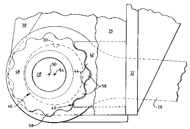
Fig. 3 is a plan view showing the parts in
the disengaged position; and
Fig. 4 is a plan view showing the parts in
the engaged position.
Best Mode for Car~y~g~ Out the Invention
Referring to Fig. 1, a vehicle 10 is shown
having a main frame 12. A first or axle structure 14
is connected to one end 16 of the main frame 12. A
second or ripper structure 18 is connected to a second
and 19 of the main frame 12. An adjustable link 20 is
connected between the axle structure 14 and the ripper
structure 18. The link 20 has a first end portion 22

zzosz4o
-3-
connected to the axle structure 14 by a pin 24. A
second end portion 26 of the link 20 is connected to
the ripper structure 18 by a pin 28.
Referring now to Figs. 2-4, the ripper
structure 18 includes a base plate 32. A first
mounting bracket 34 is attached to the base plate 32
and extends therefrom. The first mounting bracket 34
has a hole 36. A second mounting bracket 38, spaced
from the first mounting bracket 34, is also attached
to the base plate 32. The second mounting bracket 38
has a hole 40 which is the same diameter as the hole
36 and is also aligned with the hole 36 in the first
mounting bracket 34. A locking plate 42 is positioned
between the first and second mounting brackets 34,38
and is fixedly attached to the first mounting bracket
34 and the base plate 32. The locking plate 42 has an
end surface 43 opposite the base plate 32 which has a
plurality of locking lobes 44. An eccentric cam 46 is
rotatably positioned within the hole 30 of the link
20. The eccentric cam includes a locking flange 48
having a radial axis 50, and an adjustment portion 52
positioned within the hole 30 having a radial axis 54
off-set from the radial axis 50 of the locking flange
48. A hole 56 extends through the locking flange 48
and the adjustment portion 52. The hole 56 is aligned
along the radial axis 50 of the locking flange 48. An
outer periphery 57 of the locking flange 48 has a
plurality of lobes 58 which interacts with the lobes
44 of the locking plate 42. A spacer washer 59 is
positioned between adjustment portion 52 of the cam 46
and the mounting bracket 38 to prevent disengagement
of the locking flange 48 from the locking plate 42.
The spacer washer 59 includes a central hole 60. The
pin 28 passes through the holes 36, 40, 56 and 60 to

2iosl~o
-4-
mount the link 20 to the mounting brackets 34,38 of
the ripper structure 18 and prevents rotation of the
cam 46.
Industrial Abplicabilitv
In use, the link 20 of the present invention
needs to be adjustable to provide for the dimensional
tolerances between the axle structure 14 and the
ripper structure 18. The first end portion 22 of the
link 20 is pivotally attached to the axle structure 14
by a pin 24. The second end portion 26 of the link is
aligned with and between the mounting brackets 34,38.
The eccentric cam 46 is rotated to align the hole 56
with the holes 36,40 of the mounting brackets 34,38.
When the cam 46 is rotated the proper amount the link
and cam 46 is moved to engage the lobes 58 of the
cam 46 with the lobes 44 of the locking plate 42 to
prevent rotation of the cam 46. The spacer washer 59
is inserted between the cam 46 and the mounting
20 bracket 38 to prevent disengagement of the locking
flange 48 of the cam 46 from the locking plate 42 of
the ripper structure 18. The pin 28 is inserted
through the mounting brackets 34,38 and the cam 46 to
attach the link 20 to the ripper structure 18.
In view of the forgoing, it is readily
apparent that the structure of the present invention
provides an adjustable link with an eccentric cam
which is maintained in position by a looking plate
fixedly attached to the ripper structure and spacer
washer positioned between the link and the ripper
structure. The locking plate and spacer washer will
withstand the high forces associated with the ripper
being moved through the material being ripped.

210149
-5-
Other aspects, objectives and advantages of
this invention can be obtained from a study of the
drawings, the disclosure and the appended claims.

Representative Drawing
A single figure which represents the drawing illustrating the invention.
Administrative Status

2024-08-01:As part of the Next Generation Patents (NGP) transition, the Canadian Patents Database (CPD) now contains a more detailed Event History, which replicates the Event Log of our new back-office solution.

Please note that "Inactive:" events refers to events no longer in use in our new back-office solution.

For a clearer understanding of the status of the application/patent presented on this page, the site Disclaimer , as well as the definitions for Patent , Event History , Maintenance Fee  and Payment History  should be consulted.

Event History

Description Date
Time Limit for Reversal Expired 2010-09-14
Letter Sent 2009-09-14
Inactive: IPC from MCD 2006-03-11
Grant by Issuance 2004-05-11
Inactive: Cover page published 2004-05-10
Inactive: Final fee received 2004-03-01
Pre-grant 2004-03-01
Letter Sent 2003-10-10
Notice of Allowance is Issued 2003-10-10
Inactive: Approved for allowance (AFA) 2003-10-02
Letter Sent 2000-09-20
Inactive: Status info is complete as of Log entry date 2000-09-20
Inactive: Application prosecuted on TS as of Log entry date 2000-09-20
All Requirements for Examination Determined Compliant 2000-08-11
Request for Examination Requirements Determined Compliant 2000-08-11
Application Published (Open to Public Inspection) 1994-04-06

Abandonment History

There is no abandonment history.

Maintenance Fee

The last payment was received on 2003-06-17

Note : If the full payment has not been received on or before the date indicated, a further fee may be required which may be one of the following

  • the reinstatement fee;
  • the late payment fee; or
  • additional fee to reverse deemed expiry.

Please refer to the CIPO Patent Fees web page to see all current fee amounts.

Owners on Record

Note: Records showing the ownership history in alphabetical order.

Current Owners on Record
CATERPILLAR INC.
Past Owners on Record
DANIEL J. SCHARTMAN
DAVID J. BALZER
Past Owners that do not appear in the "Owners on Record" listing will appear in other documentation within the application.
Documents

To view selected files, please enter reCAPTCHA code :


To view images, click a link in the Document Description column. To download the documents, select one or more checkboxes in the first column and then click the "Download Selected in PDF format (Zip Archive)" or the "Download Selected as Single PDF" button.

List of published and non-published patent-specific documents on the CPD .

If you have any difficulty accessing content, you can call the Client Service Centre at 1-866-997-1936 or send them an e-mail at CIPO Client Service Centre.


Document
Description 
Date
(yyyy-mm-dd) 
Number of pages   Size of Image (KB) 
Representative drawing 1999-07-12 1 16
Claims 1994-05-25 2 50
Abstract 1994-05-25 1 23
Description 1994-05-25 5 137
Drawings 1994-05-25 3 56
Cover Page 1994-05-25 1 24
Cover Page 2004-04-06 1 44
Reminder - Request for Examination 2000-05-16 1 117
Acknowledgement of Request for Examination 2000-09-20 1 178
Commissioner's Notice - Application Found Allowable 2003-10-10 1 159
Maintenance Fee Notice 2009-10-26 1 170
Correspondence 2004-03-01 1 29
Fees 1996-06-11 1 46
Fees 1995-05-31 1 44