Note: Descriptions are shown in the official language in which they were submitted.
1 Dl 1-~- J-`J.~ . lG ,1 ~ (ICL ~ `J--~lt ~1;_1 ~U~ 'U
WO 93J13696 210 6 3 8 3 PCT/Cih'~3/00108
~ROVEMERTS _~ A~ EL;- ~G ~~O SEAT P~ ;E~ENTS
?ROVI~N~; r.DJl;STABLE ~ 3AR St~2PORT
~h~s fnventfon cor.cerns imorovemer.ts :n anc reia~nc :3 sea- -~
arra~gemenes prov;a_ng aa,nstaoie lumoar 3uppor- ~ an¢ more
especia!l~ to a seat st:~u~-u-e ~ae _s ~artic~iarly adapeed 'o~
use in an au.omoDile sea~ o: the ki~o wnerel3 a pla-form ele~en~
providlng suppor- or :~e up~oisee y OI the seat is resi'~ en ly
suspended in a seat frame.
-- .
It is ~.~own, see fo~ examp~e EP U 159 293, tha~ an assemD!y -o-
incorpo~alion _n a seat ~ack ~o provfde adj~uetable !umDar
G suppore .~ay compr~se a platfor~ eiemene adap_ed -o be suspended
i~ a 3eae frame to ~upport ~he cusAfon~ng of a back rest~ said
platfor~ element i~cludir.g ewo e!o~gate lateral rai~s beew~eA
which ex~e~d tran~erse mem~ers that prcvide the plat~onm
sUpport, adjustaDle ~e~ns being l~nked boeween resp-ctive
L5 portio~s of oach of said elouga~- ra~l- to apply thereto a ~orce
of longitudiu~l compre~ sion, whe~o~y s~id rails are cau~od to be
archet outw~rdly i~ the lumb~ region of tho back re~ toge~h~r
with tho transverse members carri~d thereby.
Such a~ ar:a~gement provide~ ~n adjustable and comfor~ab~e
20 lum~ar suppor. which i~ o~ reiatively sLmple desig~ has the
disadva~~age, howev-r, ~ha~ the ou~ard archlng of the lUm~7ar
egio~ o ~ b~cX rest is required tO be caused by ~lexing of
:h- olongat- l~ter~l r_ils, which a~e o~ spring wir-
con~ue:~on an~ must bo of r-latlvely heavy gauge to ~upport
t~- bon~1~g forco~ ap~l~ed thore~o by t-n~ion sprl~gs suppor~i~s
th- arran~ement in the soa~ ~r~77e an~ w~ic~ are required to
carry load plAced upon th~ plat~orm element. Thus a relatively
high force of longitud_nal compre~sion i5 requir~d to cause ~he
archi~g o~ ~e laee~l rails, pa~tic~llarl~ when the pla~or~
30 elom-nt ~s provid~ng mi~mum lumbar suppo~e and ~s in
raLativeiy flat cond~tio~. Correspond1~gly ~e~vy for~es are
thu~ placed upo~ tho ad~u~ting ars~ngement, which mUst be l~Xed
b~tw~-n ~h- Qxtr-me endg o~ the late~al rai's to givo t~e
m~Ximum mech~cal a~va~age i~ applying a benai~g ~orce ~o the
. -- .. , .-.. . . . -. . . ~.. - ., .;. .. .;, ,. . , ., . , : , ,
`L \ l ~ ) J ~ iJLL ~ 'J Ot: l 3UOl . _ ~ ' 'U
2~06383
WO~3/13h96
PCTtCB93/00108
ra:_s. ~his ?l~ces ~ n ~po~ c.~e aval_Able t~pes or
ad~us~s.g mechan1sm ~.a~ can ~e use~, as ~,ei_ as requ~ g a
,l~ar.~_ can~ space tor ~e aa;~s~~g a8ra~gemen- wlch~ s~e back
~es . _;self .
_ _~ aisa nas ~e ru_~;~es A saavan:2ce, however, s~.a~ alth~usn ~.e
degree of :~mDar suppor- car. be -ea~i!y a,-juste~ ~ ~he
horizo~tal direction, the ver-lcai pOSl~ ~ on a~ ~hic~ ~ar
suppor_ s provided is dete~s,i..ed by ~he 1~ al seome~-~c snape
o~ ~he platform elemen: a~d ~he poir.ts a; ~hic~ e compr~sion
1~ -or~_es are applied co che a.eral al!s, so that ~~ is
Lmposslb~e for an oc~panr o~ the seat .o ~tt',~ he 1~-~ar
suppor~ in a vert~cal c.ireo.ion co ~ees i~ividual reauireme~ts.
Other known svsee~s are avall~bie t~ ~rov~de 'o~ ver-:cal
adjustment of !~lmbar suppor:, bu~ ~he~e have the d1sadvantage
that ;hey a~e ~ot Adap~ab~e to the particular arra~geme~t
initially referred to. ~lso, ~uch ~now~ ~y3tem~ roquire that a
~upport e~men~ 8cUf4 up a~ down on the back o~ _he c~shioni~g
of the back re~t, ~o that some ~orm of ad~itio~al slidi~g
interface is nece-sary to allow fr-e moveme3t of the ver~ica11y
~ju~table suppor: ~e~ns.
.: is a general o~3ect of the inventio~ to provide an
i~provom-nt on an assembly of tho klnd initiall y re~erred to.
It is a pres~e~red objec~ of t~.e inJention to cvercome, o~ at
lea~e reauce one or m~r~ or ~he above mentionèd disadvanta~es.
~S I~ acco~dance wit~ one asp~ct of the ~vcn~on, this object is
ac~ievod in that the said Lateral ~ ails are provided wit~ a
hi~ged artlc~tion point i~ the region of lum~ar suppor~
wAereby outward a~ching of the rails is ef~ected by oending of
thc plat~orm elcmen: in the for~. o~ a rid~e.
Surp~isingly, it has bee~ 'ou~d th~ ~espite the fact th~t t~e
outw~rd arching of tho plat~or~ elenlene ~orms a ridge or ~pex o~
i3c~-asi~gly acute angl~, this does not, a3 ~ight ~e expected,
cau~e discom~o~- to the occupant of the seat, provided that t~e
~.
" . . .. ,. - . .,, , , . ; , "...... . .... . . . ... .
I.' J ~ UL~ ~ J~l JUOJ ~ ' 'U
2106383
3/ 1 3696
PCrtG B93/00 I n#
- 3 -
oc..-cu~:.g or ~se ?la~~o~.., e emont ~nc ~,he c~sAsoning s~lppor:ea
_hereby are apDrou~ ase`~ ~ ada~_ea o ci~.el_ purpose.
?~ o-a}~ly ;~le iatera.. -a:_ a-e -. eeiy sinceà togecr.er ~ n suc.A
a manr.er .I~.at -~.ey p; eser.~ a msnlmum -es.,os~ag force sendi:lg ~o
5 ~esls_ arC.qins, and ~..e ?!a~~c~ ei~.~er.t s sus?encea ~ e
~ack rect in suc~ a manr.e~ -hat .h~ suspensic~ spr n~s
themselves prov~ de 'c~e res;or_r.c. ~or-e encina to retu~?. ~ne
laseral rai's eo~ard~ a rec-ili~ear condition.
A~ arrangemer.e ~ n acc:~sca~ce w;~ s asD~ct o- ehe ~~vention
t~e inver.tion has ske advar.eaoe ~.h~ an ad~ust~e~ mecha~ism is
resuired to exert ii_~'e f~_~e upcn ~..e plat~o~ eiemen- a,rld may
~e !i~ked beeween E)o;n~s on ~he _aee~al rai' s e~- are
-eiaeively closely s?~ced, _.e. no~ ar :he two extrem~ ends o~
t~e rail. T~i~ en~les an adjusti~o mechanism such a~ a Bowden
cable lin~age to be used, such a lin~age ofSerins nhe advaDtages .
of economy, Sl~p~iCi~y a~d vers-tility.
Another aspect of the in~ention provides an as8embly for
incorpo~ation in a ~a~ back tO provide adiustable lumb~r
suppor~, comprisin~ ~ platfor~ el-mont adapted to ~e suspended
i a seat fra~e to suppo~t tho cushioniag of a bac~ rost, said
platform ele~-nt incLud~ng -.wo elongate la~eral rails betwe~n
whic~ extend ~ransverse me~oers that provide ~he pla~form
suppor~, wherein said plat~o~m elemen~ includes a t~a~sYerse
7 um~ar region that is ar:~culaled to~e~her witb. ~aid -ails 1
~5 th- mannes of a tra~-~ium l!nkage ia order tO enable va~ia~ion
o~ t~- ~n~ular attitu~e o~ said 1umba~ region rela~ively to the
b~se of the trapo2ium, an~ said lumbar region is li~ed to
ad~u~ting mea~s for varying th- angle thereof rel~ti~ely to a~
~djic-nc ~ection o_ e~e pl~t_~rmiele~e~, the arrangemen~ being
such th~t said ~r~atio~ o~ saic an~ie causes a ve~tical
displ~cement o~ the ~ffective oosit~on of lumbar suppor~
In ~ccor~a~ce with one em~odim~nt of the inveneion, th~ ~aid
lumbar ro~io~ of tho ~uppor~ng plat~onm ~ay be f ~rmed by a
sopara~ rocker pa~el that is piYctal!y linked betwe~ the raLls
of uppor sn~ ~ower platform s-c~io~s, t~e roc~er panel having an
- - . ......... - ... . -: , . - ,, .. ,. ~ , . ~, ,
. ~ , . : , .. ,. . . . -,; - , ~ , ... . . .
`~ ~ I 1~
-- l l ~ v v~ J u o l -- l ~ v
~ W093/13696 2106383
PCT/GB93/00108
-- 'I --
~ppr~pr:a~el~,~cc~.~ou ~i sur~~ce n ~.e~er icai 3ec_ion, ~he_eov
-.~e ver~_~ai ~051._5~ ~ -8e e~-ec~_ve u~oar s~ppor~ proviaed
ne-eDy s var~ ea ~i-s c..e ~cular at~: ~de o -ne ~ocker panel.
~ur~he. ?reter~ed f~ es ana aavan~3ges or o~e l-.ven~iOn ~15:
DecOme appa-enl f~o .;~e oilc~inc ~esc~a~ o~ ~a~en
co~junc_ on wirh ~-.e crawings, fn ~nie~:
rigu_e 1 _s a ~.C!'~ ~sle-~ Ot- an aCSemDi~l sn accordance w~
_he invent:on, shown susponced ~r~ ;he ~~m~ of ~ ~acX resc oi a
vshic~ e sea~; -
:0 ~ig~re 2 is a side ele~a~on or tha as iembly _llus~~a~ed in
.~ig.l ~i~h ;~.e -e!a-;_-re posl-ian o- ~ne suppor-i~q ~rame
illustra~ed ~ roKer. lines o~ ~~fe~nce;
Figure 3 is a geome~ric dlagram i'lus~ratLAg the effec~ive
rangeis ~nd positions of a~just~ens of t~e a~embly as
lS illustra~ed in Figs. 1 and 2,
.
Figuro 4 is a ide elev~eion illustrati~g a~ alte~naci~e
- ar~angement for providing adju-tmo~ of the assem~ly o~ Fig6. 1
a~d 2. ~ -
:. . ' .
~i~ure 5 ,s a f:on~ levatio~ of ;he bac~ rest of a s-at
incorpo~ating a~ asse~oly accordir.g to th~ nvention for
providi~g ad,ustable lumo~- suppor~, anc
~ ig~ro 6 is a diagr.lmmatic sid- eieYation illu9tra~ing she
qoome~ric~L ~rr~ngemont of the pl~tform element of the as8emb1y
o~ FL~
Roferri3g to Fig.: and 2 o~ ~he drawinss, ~here is illuslral~d
~ho fr~me 1 of a seae bac~s ~or ~he sea~ af an ~usomoblle.
Suspended within the ~r~no i~y means of ~orl~ior sp:i3g~ 2 ~ a~
as~ y, indio~ted ganerally at 3, :ha~ serves a~ a plat~on~
e~ em-nt ~or supporti~ the cushio~ing and upholstery o~ the
30 vohic7 ~ sea~ back . The plat~onn eleme~ 3 compri~o~ a~ upp~r
soc~on 4 consis~cing o~ two ~onerally ver~ical la~o~al ruils 5
' ' -
': ' " ' ,'.
., , . . ~ . . . . . . . . . .. .. .
'J~ : lt: ~.i : GE~ ~ C()-~lb ~3bl ;U~ /21J
~'O93/13696 2 106383
PCl`tC~ B93~00108
-~r~.eà -v pa~er-l~repDed seee_ ce_cs DeeWeen ~9hlcn are ~ensLonea
-_ansverse wl-es 6 pene~ra ~ng an _n~e~mea~a~e vereical cord ,.
Such a co~ss~ c~:or~ ; ~ell ~nown ~ n ~he a_ _, and a owe~
sec-~on 3 o- ~;-e ~aa 3 o ..ea ~ sL~iiar ~anner ~rom eaDer
wrap?e~ coras 9 a~d ~r~r.sve~se ~ res 10.
Secureà :o ~he upper sec~~or. ~ ~y meanS OT Cli?s 1 emD~acinq
the rai_s 5 is a sub _~.ame :2 OI rormea wire, ~n~rned en~s 12
o. whlch ro-~ p~o~s f~ a roceer panel 13 . rr. ~he ~ llus~rated
emDod~en~ ~h~ is for~ed as a flanged sheet metal p~essin5
;~ al-hous.~ - co~ld ~e -ormed b~ ~ouidias from synehetic plasnics
,~a_eria 1. Sy~_he~ic ylase~cs bu~Aes 1~ 3ec~ ed ~ithin 'lanses
;5 o f ~~e ~ocke~ ~anel 1; ce~ve as ,ou~nals for engagemen~ ~y
~c~,e encs 12~ of t:~e sub Irame.
~n a simi'ar m~nner, t.~e lower sect~o~ 8 is prov1ded wit~ a ~u~
15 'relme 16 i~tu~ned ends 16A of whick engage in bushes 17
suppo~ed iD. the f lange 1~ .
Th~ rwo suS~ fra~ne~ 12 and 16 are 9p~inq bia~ed relatively to t~e
rocker panel 13 by means of dou~le ~c~i3g to~ion ~prings 18,
oac~ of which extends around both of the adjacent int-arned end~
20 '2~ and 16A of t~e re~pec~iv- ~ub f~ame~, t~ spri~g~ 18 s-rving
tc bias the ~Qsembly so t~at t~e sec~ions 4 and 8 ~nd the soc~es
p~nel 13 are urqed _owardt the relat ~e ang~lar posit~ons
i!lus~ratod in Fig.2.
The sub f~ame 12 is ro~ed to include U-shaped loops 12~ withi~
which are anc~ored doublo-soc~et fer-ules 13 for the
co~nocrion of two p~irs of 90wden cables 20 and 21 respectiYely.
~ach pal- of ca~les is as~ociated with a common actuacing me~ns
Z2, 23 respectively, which wi_l be described in more detail
b-low.
An acsua~ing cable ZOA (Fig.2) of ~ac~ Bowden cabLo 20 is
anchored to a corresponding fla~g~ 15~ of t~e rock-r panel 13,
at 22. Likcwise, a~ dctua~ sg cable Z'A ~Fig.2) o~ e~ch Bowdcn
- c~le 21 is connected to an a~chora~e 24 supported is~ a u-shap-d
loop 16~ of tho 6ub ~ramo 16.
-: : ................... - .
. - : - :
. : : ' . .
~E.\T 6~ 9 93 ~ EE~ C~ b 961 ;~ 9/2~
` WO93~13696 2 1 0 6 3 8 3
PCT/GB93/00108
,,
,ince _ne ,prir.~s 1~ c~use ^he _oc.~er ?anei 13 to ~e biasea
a~ou~ ~he pi~o.s 6A _:~ a c!3c.~wlse di-ection a5 vlewe~ in Fig.
and _o De biasec aDou- ^..e p~vo~s 12A _n a cl~ck~lse di_ect'on
2S V~ ewea 1 n ~ 5.', -.~e a~~~sceme~~ l5 such ~ha~ wnen, start:nc
__om -~.e pos ~ior. shown ~r. ~is.2, t~e Bowden ca~le 20 ls
co~t-ac~c ~o reduce ~.e d_s~arce be~-~ee~ _he fer-ules :g and
the anc~,oraqes ~2, the rocke~ oanel 13 is pivoted ir. the ant_-
clockwlse d_rec-ion r.o va-l ~ts a~ti~~de reiatively :o the
verticai plane, whereas whe~ ehe ~owden cables 21 are cont~acled
to re~uce t~ dis.ance be~ween the ancnorages 24 and ~he
fe~r~les _9, ~he ;.ape!z~um ~r~.~age rormed by ~he su~ ~rames 12
and ;6 a~d ~.e rocxe~ ?ar.el 13 is caused tO a-_h out~araly to
the le~~ as v_~w~c i.. F~g.'. Upon relea3e or the ~spectiv~
3owQen cables, the spr.ir.gs 1~ will tena .o re~urr. ehe assem~ly
~5 to t~.e posit~on of ~i~.2.
: , ' ' ' '
Thus~ by means of :he controis 22 and 23 the platform element 3
c~n bc adju~ted to pro~ido a variety of con~igura~ions of lwmbar
support, as c~n be ~een moro clearly by referenco to tho d~agram
of Flg.3.
In ~ig 3 the link~ge points are ~iven the sa~- referonce
numorals a~ in Fig 2, a3d thus the figure de~i~ed by the poi~ta
19,24,16A and 12~ snows the attitude of the arra3g-meut a~ in
~ig 2, in which the lumbar suppor~ iS effectively providea at
the point 16A. 8y control of ~he ~ctuating ~eans 20 tho rocker
2S panel 13 ca~ be t~lted pro~ressively to provide a ran~e of
adjust~ent in which the points 12A and 16A are mo~ed through the
pO~ition~ 12A',16A' to position~ 12~'',16A'' at which ~he lumbar
~uppor~ is prcvided ~t he point 12A''. Th- con~o~r of ~h~
pa~el 13 is such that this hds the effect of mo~ing the lum~ar
30 sup~ort progressi~-ly through th~ vertical distance bo~ween ehe
: points 16A ~d S2A''.
5tar~ fro~ Ch~ po~ition i~ FLg 2, con~rol of tho actua~ing
mea~ 21 can mo~e t~o point Z4 vertically r~lati~ely to t~e
poi~ 19, to the po~tio~ 24~, g~vi~g ~ rang- o~ horizontal
3~ adjust~nt o~ the lumb~r s~pport boewe-n the poi~t~ lCA and
'' '.. ' ' '
~'() 93/136~6 210 6 3 ~ 3 PCT/GB93/0010~
,
:6~ ''. Con~ oi cl ~-e ac~ g mear.5 20 can ehen be u5ea, as
ai~eady de~c ibed, ~o ~ove tr.e lumDar suppor_ ver~ oai_~ ~rom
the Foln~ '6A~ ' so t~.e pof n~ :2~
g.4 i`lust_ases an ar-angemen; CO~ ac~uarl~q the Bowaen cable
kages 20 anc 21 as descr bed aoove. ~he ou~er sheacr. o eacn
o- -he ca~les 20 ~s ~ecelved _n a ferruie b!ook ~5, whereas ~.e
i~ternal ca~les 20A are connec~et to a further block 26. The
~locks 25 and 26 are f~ screw threaded enga~emen- with a lead
~crew Z7 having let~ and ~igh~ han~ed screw sect ons 27A and 27~
i0 ~espec~ vely. Thus ~ota~ion of the leac sc~ew ~7 is ef-ec~ive
~c cause ;he blocxs Z5 and 26 ~o be m~ved towaràs or away from
one another in order _o ac;ua~e ~he Bowden cabl~s 20 i~ the
~ense requlred.
~e ~owden cables ~' ar.e connec~ed in a sim~}ar ~anner to blocks
2~ and 29 located upon a sL~ r lead screw 30.
~be lead ecrewe 27 and 30 can ~e actua~ed by mea~s o a ~wo-part
control ~ob 31, a~ inner portion 32 of which i~ fix-d directly
to the l~ screw 30 and is provided with appropriste fi~g-r
recesses, not shown, to facilitare rotatlo~, and an outer
20 circumfere~tial por~ion 33 of which is coupled to a spur gear 34
t~at is freeiy rota~able abou~ a~ unthreaded ~ect~on of ~he lea~
sc~ew 30.
She ~pur gear 34 is coupied via an id~er ge~r 35 ~ounted on a
rotary sha~t 36, to a further spur gear 37 that is fixed to the
load c~-w 27.
~hus tho arrange~en~ is such t~At by manip~lation of t~e section
32 of ~he control kn~, an ocoup~n~ of the sea~ ean vary tho
degree of lu~oar support in the hori~ontal direction by means of
the 3Owden cable- Zl, ~herea- by ~ndependent rota~ion of the
outer circum~eronce 33 of th~ co~trol k~ob ~he 3Owden ca~le~ 20
can be actuated to provide ver~ical adj~stment o~ the polnt o~
lum~ar suppo~t.
.~- ~ ., - . : : : :- '
~L~ J JJ ' ~JL,L ~ Jl~_ V;I Jl_lG~
'0 93/13696 210 6 3 8 3 PCr~GB93/00108
-- 8 --
t ~ oe app~ecl~ted ;ha~: var~ o~-s altera~:ons anc
moci__catlons may be ma~e co she arr~ncemen: descr_be~ aDove
wa_hous ~epar~ q ~_e~ ~he scope o~ -he _evens~or., ~hus, n
?lace e. e~e two-~ar- coa~-oi .knob 31, separa~e cont-ol ~30~s
may be ir.~ependen !s con3ecte~ ~o ~.e lead screws 27 and 3~ as
lluse-ated in ~ig. ~
~_ des'rea, ~~e ~rapezi~ kage illust.ace~ io ~lgs~_ anc 2
may ~e provide~ wit. stop ~eans _o~ preventi~g the lin~age f c~,
s~apping over ~entre under load appliec to the seat~ ~hu~, or
ax~ple, the rocker p~ne 1 _3 may be prov~de~ ~it~ an extenced
lug ~or engagemene aaalnst the su~-~rame 1~ in orde- -o i~it
tne ra~ge o~ movement o~ the soeker ?anel _3 rela~ively shere~o,
so th.a~ .he pivoe ?cincs 12~ can~o~ ~ass ove~ cer.e~e beewees ~.e
po~ts 16A and _he poants 19.
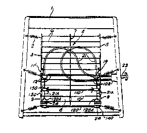
Rererrins to ~ig6. 5 and 6 of the drawings there is shown
ano~her embod~ent of rhe in~en~ion wherein like parts a~e
i~dicated wilh the ~a~o reference numerals ~ in Figs. 1-4 and
thus will not be de~cri~ed again in detail. In this arrangemen~
t~e rocke~ panel 13 i5 omitted and additio~al transver~ wires
20 110 and 120 of heavier gauge than the wires 10 are connec~ed
be~ween the wires 9 by means of cliFs 130 an~ 140 to comple~e a
rec_angular outer .:~e of the lowe_ s~c~ion 8.
Clips 150 secure ehe tra~sve-se wire 110 to inturned ends o~ _he :
coras ~, whereby :he c'ips 15 se~ve A5 hinces that allow the ;wo
sec:ion~ 4 a~ 8 of -h~ platform ele~ent :o be hinged ~elatively
to one anoeher aoout the ~ansverse wi:e 110.
~he ~:ansverse wire 120 has hoo~ed ends 1 20A ~h~t serve as
anc;~ora~es for ~he grooved blocks 2~ ~ha~ f ' t withln the hoo~s
120A anc aro anoho~ed to t~e ends o- Bowden cables 21~.
3~ _n a sLmil~r m~n~er tO the arrangement o~ Figs. 1-4, a furcher
tra~sverse sceel wire 12' is connected ~etween the cards S ~y
m-ans o~ clips 11' and ha~ looped porlions 12~' that serve to
rec~i~ the grooved ~locks lg forming ~err~le5 for th~ ouc~r
sleeves 21 of t~e Bowden caoles.
~ 210~383
Wo 93tl3696
PCT/c B93/OU 108
-- 4 ~
~e~er-ang co ~rig~ /ill be seen :~a~ _~.e loweo se-_t_on a of
-~.e plac~orm elemenr an.~ ooe iower sec:lons of ~ords 5 exsending
DetWeen _he ferru1es i9 and ~he c1~ps 150 -o~ a t_:ang~.~iar
rLd5e~ o~e base of :~e o~iang!e oe}ng def1ned by the ~or~fons o~
30wden cao 1 e 21~ ex~endi~g betwees ~he sr.c~oraces 24 anà
'er_~ies ' 9 . T~e 30wden caDles 21~ are h~ld ~r.~er s!1~nt
sension by means of ~r~e oension sprin~s ' ~h.at anchor ~he
plarform element t in nhe sea~ frame 1, and thus the angle of
the apex of the t~_ansular r~dGe i5 de~erms..ed by :~e len~ch of
the Bowden cables 21~ exlendi3g between poir.~s 24 ~nd 1g, ~hich
distanc~ can be ad~us~ed by m~nuai aceua~ion o. he mecha~sm
23. '
It wi_' thus be seen tha- ef~ecti~e a~jusumenr of ~;~e degree af
. horizonlal lumoor 8uppo.t provided by t e plat40r~ ~lement 3 c~n
lS ~e achieved i3 a sfm~le manne~ Dy t~e mechaniom 23 without ~ho
~eed for the mechanism to exer~ 6ig~ificant forc~ upon ohe
platform ~l-mont 3, o~t wit~out th- need for the ad~ustin~
m-chanism to oxtend to the fU11 height of th- platform e~emen~
3. $~us ~ r-lati~1y co~pact ~implo and economical adjusting
~ch~ism c~n ba uood.
.., ~
' '''.'
.