Note: Descriptions are shown in the official language in which they were submitted.
TITLE
PORTABLE COLLET CRIMPING APPARATUS
BACKGROUND OF THE INVENTION
This invention relates in general to devices for
crimping fittings onto the ends of hoses and in particular
to a self-contained, portable collet crimping apparatus.
The collet crimping machine is a well known device
which is adapted to secure a cylindrical end portion of a
metallic fitting onto an end of a high pressure hydraulic
hose. Initially, the end portion of the fitting is formed
having an inner diameter which is slightly larger than the
outer diameter of the hose, permitting the end of the hose
to be loosely inserted therein. Then, the end of the hose
and the fitting are inserted within the collet crimping
machine. When the collet crimping machine is actuated, the
fitting is crimped so as to permanently deform the tubular
end portion thereof about the end of the hose.
To accomplish this, a typical collet crimping machine
is provided with a hydraulic actuator which is adapted to
engage a contractable die assembly. The hydraulic actuator
includes a cylinder having a piston slidably disposed
therein. When pressurized hydraulic fluid is supplied to
the interior of the cylinder, the piston is moved from a
first position to a second position. The die assembly
typically includes a die ring having a tapered inner
surface and a plurality of collet segments disposed within
the die ring. A spacer or pusher is disposed between the
piston of the hydraulic actuator and the collet segments.
Thus, when the piston is moved to the second position, the
pusher is moved to engage and move the collet segments.
Because of their engagement with the tapered inner surface
of the die ring, the collet segments are contracted
2~p~4~~
2
inwardly toward one another, thereby crimping the fitting
disposed therein about the hose.
Typically, the die assembly is removable from the
collet crimping machine. This is done to permit the
installation and removal of collet segments of different
sizes, which permit the collet crimping machine to crimp
fittings of various sizes onto hoses of various sizes. To
facilitate the installation and removal of the collet
segments, it is known to provide a pusher which is
removable from the collet crimping machine. Such removable
pushers provide convenient access to the die assembly when
changing the collet segments. However, when these pusher
are re-installed in the collet crimping machine, they must
be carefully aligned between the piston and the die
assembly in order to function properly. This careful
re-alignment has been found to be undesirably time
consuming after each change of the collet segments. Also,
although removable pushers are typically retained to the
collet crimping machine in some manner, such as by a chain,
they have occasionally become separated therefrom and lost.
Accordingly, it would be desirable to provide a collet
crimping machine wherein the pusher is secured thereto, yet
which is movable between extended and retracted positions
to facilitate changing of the collet segments.
As mentioned above, the collet crimping machine
typically includes a hydraulic actuator which is operated
by the application of pressurized hydraulic fluid thereto.
In a manufacturing situation, the co:llet crimping machine
can be connected to any conventional external source of
pressurized fluid which is commonly available in the
manufacturing environment. However, often it is necessary
to repair fittings and hoses in the field, where a source
of pressurized fluid is not readily available.
Accordingly, it would also be desirable to provide a collet
crimping machine having a self-contained source of
2~~~~2$
3
pressurized hydraulic fluid, thereby facilitating the use
thereof in the field.
SUMMARY OF THE INVENTION
This invention relates to an improved structure for a
collet crimping apparatus which is self-contained and
easily portable for use in the field. The apparatus
includes a base having a hand-actuated hydraulic pump
assembly mounted thereon. A collet crimping machine is
pivotably mounted on the base so as to be adjustably
oriented at any desired angle. Means are provided for
selectively retaining the collet crimping machine in a
desired rotational position relative to the base. The
hydraulic pump assembly is connected to actuate the collet
crimping machine. Thus, the collet crimping machine has a
self-contained source of pressurized hydraulic fluid,
thereby facilitating the use thereof in the field where a
source of pressurized fluid may not be readily available.
The collet crimping machine further includes a pusher
which secured to the machine to prevent loss, yet which is
slidable between extended and retracted positions. In the
extended position, the pusher is disposed outwardly away
from the collet crimping machine to permit easy replacement
of a die assembly. In the retracted position, the pusher
is disposed within the collet crimping machine and
precisely aligned with the other components thereof for
use. The pusher may have an outwardly extending handle
connected thereto to provide a convenient grasping location
for an operator to effect sliding movement of the pusher.
Means are provided for positively retaining the pusher in
the retracted position for use.
Various objects and advantages of this invention will
become apparent to those skilled in the art from the
following detailed description of the preferred embodiment,
when read in light of the accompanying drawings.
2~.~G428
4
BRIEF DESCRIPTION OF THE DRAWINGS
Fig. 1 is an elevational view of the left side of a
portable collet crimping machine in accordance with this
invention, wherein the pusher of the machine is shown in an
extended position.
Fig. 2 is an elevational view, partially broken away,
of the front side of the portable collet crimping machine
shown in Fig. 1, wherein the pusher of the machine is shown
in an extended position.
Fig. 3 is an elevational view of the right side of the
portable collet crimping machine shown in Fig. 1, wherein
the pusher of the machine is shown in an extended position.
Fig. 4 is a side elevational view from the right of
the portable collet crimping machine similar to Fig. 3,
wherein the pusher of the machine is shown in a retracted
position.
Fig. 5 is an enlarged side elevational view, partially
in cross section, of the upper portion of the portable
collet crimping machine shown in Fig» 2.
DETAILED DESCRIPTION OF THE PREFERRED EMBODIMENT
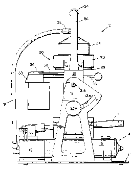
Referring now to the drawings, there is illustrated a
portable collet crimping assembly, indicated generally at
10, in accordance with this invention. The collet crimping
assembly 10 includes a base plate 11 having upstanding left
and right support brackets 12 and 13 secured thereto, such
as by welding. The left bracket 12 has an arcuate slot 12a
formed therein for a purpose which will be explained below.
A hydraulic pump assembly, indicated generally at 14, is
also mounted on the base plate 11. The pump assembly 14
includes a fluid reservoir 15, a cylinder 16 containing a
movable piston (not shown), and a pivotable handle actuator
17. In operation, an operator may grasp and pivot the
handle actuator 17 relative to the Bump assembly 14 to
cause movement of the piston within the cylinder 16,
210~~2~
thereby creating a flow of pressurized fluid from the fluid
reservoir 15 to a flexible output conduit 18. The purpose
for generating this flow of pressurized fluid will be
explained below.
5 The collet crimping assembly 10 further includes a
collet crimping machine, indicated generally at 20, which
is pivotably mounted on the support brackets 12 and 13.
The collet crimping machine 20 includes left and right side
brackets 21 and 22 which are pivotably connected to the
left and right support plates 12 and 13, respectively, by
pivot pins 21a and 22a., Thus, the collet crimping machine
is supported on the support brackets 21 and 22 for
rotation about an axis which extends though the aligned
pivot pins 21a and 22a. This axis of rotation is
15 preferably co-axially aligned with the center of gravity of
the collet crimping machine 20. Thus, the collet crimping
machine 20 pivots easily about the axis of rotation.
Means are provided for selectively retaining the
collet crimping machine in a desired rotational position
20 relative to the base plate 11. In the illustrated
embodiment, this means for selectively retaining includes a
knob 20a having a threaded shank (not shown) extending
outwardly therefrom. The threaded shank of the knob 20a
extends through the arcuate slot 12a formed in the left
support plate into threaded engagement with a
correspondingly threaded aperture (not shown) formed in the
left side bracket 21. When tightened, the knob 20a causes
the left support plate 12 to frictionally engage the left
side bracket 21. As a result, the collet crimping machine
20 is prevented from rotating relative to the base plate
11. Upon loosening of the knob 20a, the collet crimping
machine 20 may be rotated to a desired angular disposition
relative to the base plate 11. The limits of such relative
rotation are defined by the extent of the arcuate slot 12a,
2 I 0 6 ~~.8
6
inasmuch as the threaded shank of the knob 20a extends
therethrough.
The upper ends of the side brackets 21 and 22 are
connected to the opposed sides of a cylinder ring 23, such
as by welding. As best shown in Fig. 5, the inner surface
of the cylinder ring 23 is formed having an internal
thread. This internally threaded surface of the cylinder
ring 23 is cooperates with a lower externally threaded
outer surface of a cylinder housing 24. A hydraulic
fitting 25 is threaded into an aperture formed through the
upper portion of the cylinder housing 24. The fitting 25
provides for fluid communication between the flexible
conduit 18 of the pump assembly 14 and the interior of the
cylinder housing 24. Thus, when the pump assembly 14 is
actuated by movement of the handle acauator 17, pressurized
hydraulic fluid is introduced into the upper end of the
cylinder housing 24.
A piston 26 is disposed within the interior of the
cylinder housing 24 for sliding movement. A conventional
seal assembly 27 is provided in an outer circumferential
groove formed in the piston 26. The seal assembly 27
provides a relatively fluid tight seal between the piston
26 and the inner surface of the cylinder housing 24, while
permitting relative movement. When pressurized hydraulic
fluid is introduced into the interior of the cylinder
housing 24 as described above, the piston 26 is urged
downwardly within the cylinder housing 24. A return spring
28 is provided for urging the piston 26 upwardly within the
cylinder housing 24 when the pressurized fluid is removed
therefrom. The return spring 28 is disposed within a
counterbore 26a formed in the piston 26. The return spring
28 reacts against a retainer plate 29 which is secured to
the lower end of the cylinder ring 23 by a plurality of
threaded fasteners 29a.
2I~6~28
A slide plate 30 is secured to the lower end of the
piston 26 by a plurality of threaded fasteners (not shown).
Thus, the slide plate 30 moves upwardly and downwardly with
the piston 26 as described above. The slide plate 30 has
an elongated slot 31 formed therethrough. Also, the slide
plate 30 has a generally semi-spherical recess 32 formed in
the lower surface thereof, adjacent to the slot 31. A
pusher 33 is supported beneath the slide plate 30 for
upward and downward movement therewith. To accomplish-
this, a slide flange 34 is disposed above the slide plate
30. The slide flange 34 includes an upper portion which is
disposed adjacent (and is adapted to slide along) the upper
surface of the slide plate 30. The slide flange 34 further
includes a depending portion 34a which extends into the
elongated slot 31 of the slide plate 30. The pusher 33 is
connected to the slide flange 34 by ane or more threaded
fasteners 35, which also extend through the slot 31.
The slide plate 30 is only loosely engaged between the
upper portion of the pusher 33 and the lower surface of the
slide flange 34. Thus, the pusher 33, the slide flange 34,
and the threaded fasteners 35 may be moved as a unit
laterally relative to the slide plate 30 and the remainder
of the collet crimping apparatus 10. The depending portion
34a of the slide flange 34 is provided to guide the slide
flange 34 (and the pusher 33 secured thereto) for sliding
movement along the slide plate 30. '.rhe limits of such
lateral movement are defined by the engagement of such
depending portion 34a with the ends of the elongated slot
30a formed through the slide plate 30.
Thus, the pusher 33 may be moved between an extended
position (illustrated in Figs. 1 through 3) and a retracted
position (illustrated in Figs. 4 and 5). In the extended
position, the pusher 33 is disposed outwardly away from the
piston 26. In the retracted position, the pusher 33 is
disposed directly beneath the piston 26. A handle 36 is
2100~2~
8
connected to the pusher 33 for movement therewith. The
handle 36 extends laterally outwardly from the collet
crimping machine 20 and provides a convenient grasping
location for an operator to effect sliding movement of the
pusher 33. The purpose for mounting the pusher 33 on the
collet crimping machine 20 in this manner will be explained
below.
Means are provided for positively retaining the pusher
33 in the retracted position. In the illustrated
embodiment, such means includes a stepped counterbore 33a
formed in the upper surface of the pusher 33. A ball 37
and a spring 38 are disposed within the counterbore 33a.
The sgring 38 urges the ball 37 upwardly against the lower
surface of the slide plate 30. When the pusher 33 is
disposed in the retracted position, the ball 37 is urged by
the spring 38 into the semi-spherical recess 32 formed in
the lower surface of the slide plate 30. Thus, the pusher
33 is positively retained in the retracted position. Also,
when the pusher 33 is moved from the extended position to
the retracted position, the ball 37 snaps into engagement
with the recess 32. This engagement provides a tactile
indication to the operator that the pusher 33 is properly
positioned for engagement by the piston 26, as will be
explained below.
The collet crimping machine 20 further includes a die
assembly, indicated generally at 40. The die assembly 40
includes a die ring 41 which is secured to the lower ends
of the left and right support brackets 21 and 22, such as
by welding. The inner surface of the die ring 41 is
tapered, as shown at 41a in Fig. 2. A plurality of collet
segments 43 are disposed in an annular array within the
tapered inner surface 41a of the die ring 41. The die
assembly 40 further includes a spacer ring 44 which is
disposed above the collet segments 43. The spacer ring 44
is sized to be engaged by the lower end of the pusher 33
9
when the pump assembly 14 is actuated to move the piston
26, as described above.
As is known in the art, the die assembly 40 is
provided to crimp a fitting onto the end of a hose. To
accomplish this, the hose having the fitting loosely
carried thereon is inserted within the collet segments 43
of the die assembly 40. Then, the pump assembly 14 is
actuated by movement of the handle actuator 17 so as to
cause the piston 26 and the pusher 33 to moved downwardly
into engagement with the die assembly 40. Because of the
cooperation of the collet segments 43 with the tapered
inner surface 41a of the die ring 41, the fitting is
crimped onto the end of the hose.
As described above, the collet crimping apparatus 10
is preferably adaptable for use in crimping fittings of
various sizes onto hoses of various sizes. To accommodate
these different sizes, a plurality of differently sized
groups of collet segments 43 are provided for use with the
die ring 41 and the spacer ring 44 of the die assembly 40.
These differently sized collet segments 43 permit the
collet crimping machine 20 to be used with a number of
differently sized fittings and hoses. Thus, it is
important that the collet segments 43 and the spacer ring
44 be easily removable from the collet crimping machine 20
to facilitate change from size to size.
The slidable pusher 33 of this invention facilitates
this changing of the collet segments 43. As described
above, when in the extended position, the pusher 33 is
disposed outwardly away from the piston 26. As a result,
easy access is provided to the colle.t segments 43 and the
spacer ring 44. Thus, the set of collet segments 43 can
quickly be removed and replaced with another set of collet
segments of different size. When in the retracted
position, the pusher 33 is disposed directly beneath the
piston 26 for use in the crimping operation. Throughout
21~~~28
this entire process, the pusher 33 remains secured to the
collet crimping machine 20, thereby preventing the
accidental loss thereof.
Because the pump assembly 14, the fluid reservoir 15,
5 and the crimping machine 20 are all mounted on the base
plate 11, it will be appreciated that the collet crimping
apparatus 10 is a totally self-contained unit which is
readily portable and easily adapted for use in the field.
A generally L-shaped carrying handle 50 is provided for
10 moving the collet crimping assembly 10 from location to
location. The handle 50 is secured to a mounting plate 51,
such as by welding. The mounting plate 51 is secured to
the upper end of the left side bracket 21 of the collet
crimping machine 20, such as by welding.
If desired, a conventional grip 54 may be mounted on
the end of the handle 50. The grip 54 of the handle 50 is
preferably located directly above the center of gravity of
the collet crimping apparatus 10. As mentioned above, the
collet crimping machine 20 is supported on the support
brackets 21 and 22 for rotation about an axis which is
preferably co-axially aligned with the center of gravity of
the collet crimping machine 20. Thus, regardles of the
angular orientation of the collet crimping machine 20, the
handle 50 can be grasped to conveniently pick up and move
the entire collet crimping apparatus 10 from location to
location.
In operation, the portable collet crimping apparatus
10 can be transported to a desired location by means of the
carrying handle 50. Once properly located, the angular
disposition of the collet crimping machine 20 can be
adjusted relative to the base plate 11 by loosening the
knob 20a. The collet crimping machine 20 is rotated to a
desired angular disposition, then the knob 20a is tightened
to maintain it in that position. Next, the pusher 33 is
moved to the extended position by pushing on the handle 36.
2~~~~~$
11
As a result, the pusher 33 and the slide flange 34 are
moved relative to the slide plate 30 and the remainder of
the components of the collet crimping assembly 10.
As described above, access to the collet segments 43
is permitted when the pusher 33 is in the extended
position. Thus, while the pusher 33 is in the extended
position, the appropriately sized collet segments 34 are
inserted within the die ring 41, and the spacer ring 44 is
replaced above the collet segments 34. Then, the handle 36
is grasped so as to move the pusher 33 from the extended
position to the retracted position. As mentioned above,
when the pusher 33 is moved from the extended position to
the retracted position, the ball 37 snaps into engagement
with the recess 32 to positively retain the pusher 33
therein and to provide a tactile indication to the
operator.
In accordance with the provisions of the patent
statues, the principle and mode of operation of this
invention have been explained and illustrated in its
preferred embodiment. However, it must be understood that
this invention may be practiced otherwise than as
specifically explained and illustrated without departing
from its spirit or scope.
30