Note: Descriptions are shown in the official language in which they were submitted.
$ ::
COSMETIC PACKAGE
BACKGROUND OF THE INVENTION
1. Field of the Invention
The present invention relates to cosmetic
packages and, more particularly, to a package for
holding a series of sticks provided with a cosmetic
product.
2. DescriPtion of the Prior Art
Various prior art cosmetic packages have
already been proposed. For instance, United States
Patent No. 4,687,099 issued to Van Buuren on August
18, 1987 discloses a package for sticks each having
a head portion coated with a cosmetic product. The
package includes a sliding tray having upstanding
side walls of which two opposite walls are provided
with an incision so that one part of the sliding
tray can pivot with respect to the other part of the
sliding tray. The cosmetic sticks are releasably
attached to the sliding tray which is înserted in a
wrapper. Therefore, slidably removing the tray from
the wrapper at least until the incision allows one
part of the sliding tray to pivot with respect to
the other will partially reveal the sticks for
easier removal thereof from~the other part of the
trAy~ The me~ns used for hoIding the cosmetic sticks
in place in the tray include, for instance, a piece
of corrugated cardboard or a piece of molded plastic
defining a~series of grooves of widths corresponding
to the diameters of the sticks thereby allowing the
cosmetic sticks to be removably attached to the
sliding tray.
U.S. Patent 2,775,249 issued on December
25, 1956 to Morrell discloses a matchbook-type
cosmetic package which consists of a base sheet, a
cover integral with the base sheet and foldable
":', .' :'
- 1 -
-...;~,.-
''~'' ' '
2 ~ 8
thereover, and a lip which is preferably anextension of the base and which folds rearwards to
hold the cover in position when it is closed. Rods
which are tipped with lip rouge are inserted in -
pockets formed by the use of fastening means, such
as staples. A powder puff or pad is carried inside
the package, preferably in an envelope.
U.S. Patent 3,976,185 issued on August 24,
1976 to Cohen discloses an improved sealed package
which includes one or more disposable handled swabs
or applicator sticks and a medicinal material to be
applied by the heads of the swabs or applicator
sticks. The package has the form of a tray molded in
such a way as to provide for each applicator stick a
well that serves loosely to receive the head portion
thereof and isolate it from external compression
forces. An inclined support ledge positions the
handle portion of each applicator stick so it is
inclined upwardly and away from the well. A cover
sheet made of a gas-impervious material is secured
over the tray to provide a gas-tight seal that is
selectively openable to provide access to the swabs
or applicator sticks. The handles of the swabs are
preferably engaged and depressed by the cover sheet
to hold the swabs securely within the package.
U.S. Patent 4,337,859 issued on
July 6, 1982 to Murphy et al discloses a method for
producing a cosmetic product containing an
integrally molded powder cake. The product includes
a casing having an open top enclosed by a cover with
the casing defining a cavity to contain the powder
cake. In the method, with the cover closed, the
casing in inverted and a slurry is introduced into
the cavity through an opening in the bottom of the
casing. Once cooled, the slurry forms the powder
cake. -
.. ,,~
.. ..
Finally, U.S. Patent 4,714,160 issued on
December 22, 1987 to Bennett teaches a dispenser
which comprises a horizontally elongated base having
first and second opposite flat surfaces. A plurality
of spaced elongated rods are each secured at one end
thereof by an integral short thin prong to the first
surface and extend outward in a common direction at
right anyles to the base. The opposite end of each
rod has a coating. An elongated support member is
disposed in a plate parallel to the common plate of
the rods while being spaced from the articles and
being secured at one end to the base. A horizontal
elongated plate parallel to the base and secured at
one of the elongated edges to the other end of the
member is disposed adjacent but spaced from the
coated ends of the rods. First and second elongated
article support elements contact the rod and are
secured to the support member. The parallel support
members each define straight parallel grooves which
are disposed side by side and in alignment with each
other for detachably carrying the rods. A
transparent plastic hollow cover detachably engages ;
the base to enclose the elongated rods while being
spaced therefrom.
SUMMARY OF THE INVENTION
It is therefore an aim of the present
invention to provide an improved cosmetic package.
It is also an aim of the present invention
to provide a cosmetic package comprising an
open-ended box-like casing, a closure for the casing
pivoted at one end thereof, and a tray also ~-
pivotally mounted to the casing and detachably
carrying thereon a series of cosmetic sticks.
It i5 a further aim of the present
invention to provide a cosmetic package adapted to
protect the cosmetic sticks and thus prevent the
- 3 - ~
'::
2 ~
smearing thereof inside the cosmetic package and,
more particularly, inside the casing and the tray
thereo~.
Therefore, in accordance with the present
invention, there is provided a package comprising a
plurality of elongated sticks, an open-top casing
means including a bottom wall and side walls
extending upwards therefrom, a closure means
pivotally mounted to one of the side walls, a tray
means pivotally mounted to another one of the side
walls. The tray means is adapted ~or detachably
carrying thereon the elongated sticks and for
retracting, in a closed position thereof, in the
casing means with the closure means being adapted,
in a closed position thereof, for covering the open
top of the casing means. Therefore, the tray means
and the elongated sticks are enclosed within the
casing means and the closure means in the above
closed positions.
In a more specific construction in
accordance with the present invention, the tray
means comprises on an unders:ide thereof facing, in
the closed position of the tray means, the bottom
wall of the casing means at least a pair of spaced
apart elongated notched members each defining a
series of notch means, with each notch means of one
of the elongated notched members cooperating with a
respective notch means of the other one of the
elongated notched members for detachably carrying an
elongated~stick.
Also, stop means are provided in the
casing means for limiting the downwards pivot of the
tray means therein in the closed position thereof.
Furthermore, a first opening is defined in
the tray means which is in substantial alignment
with a second opening defined in the closure means,
''
- 4 -
2 ~ 8
when in the aforementioned closed positions thereof,
for viewing at least parts of the elongated sticks
when the package is closed.
Preferably, a clear window is mounted to
the second opening for isolating the elongated
sticks when the package is closed.
In a specific construction, the casing
means, the closure means and the tray means are all
made of a plastics material. Also, integral plastic
first and second hinge means pivotally join the
casing means resp~ctively with the closure means and
with the tray means on opposite side walls of the
casing means.
Moreover, the closure means includes a
ledge means extending from a front edge thereof and
defining at least one inwardly projecting tab means
for cooperating with the second hinge means for
maintainiAg the closure means clipped to the casing
means in the closed position thereof.
Preferably, the closure means springs up
at least partly when the tab means are released from
enga~ement with the second hinge means for
facilitating the grasping of the closure means.
Also, a mirror is provided on at least one
of an underside of the closure means and on an upper
surface of the bottom wall of the casing means.
Preferably, the mirror is adhesively mounted to the
package.
In all constructions, the elonqated sticks
may consist of cosmetic sticks each having a handle
. . .
portion adapted to be removably attached to the
elongated notched members and a head portion
provided with at least one cosmetic product and
adapted to be viewed through the window, when the
package is closed.
..:
'. ' '~:
_ 5 _ :
' ': '
Also in accordance with the present
invention, there is provided a package comprising a
plurality of elongated sticks, an open-top casing
means, a closure means and a tray means both
pivotally mounted to the casing means, the tray
means being adapted for detachably carrying thereon
the elongated sticks and for retracting, in a closed
position thereof, in the casing means with the
closure means being adapted, in a closed position
thereof, for covering the open top of the casing
means, whereby the tray means and the elongated
sticks are enclosed within the casing means and the
closure means in the closed positions, the closure
means being adapted for allowing at least parts of
the elongated sticks to be viewed when the package
is closed.
BRIEF DESCRIPTION OF THE DRAWINGS
. Figure 1 is a perspective view of a
cosmetic package in accordance with the present
invention, shown in its closed position;
Figure 2 is a perspective view of the
cosmetic package of Figure 1 but shown in a partly
open position, wherein a cover of the cosmetic
package is open;
Figure 3 is a perspective view of the
cosmetic package of Figures 1 and 2 but shown in a
fully open position, that is with the cover and a
tray thereof being open;
Figure 4 is a transversal cross-sectional
view of the cosmetic package, shown with its tray
fully retracted in the casing and its cover in
extended open position;
Figure 5 is a longitudinal cross-sectional
view taken along lines 5-5 of Figure 2;
Figure 6 is a top plan view of the
cosmetic package of Figure l;
. .
- 6 -
, ' ' ' ' . ' '' ! ' ' ' ~ . ' ' : ' . ', ' ,; :
L8
Figure 7 is a perspective view similar to
Figure 2 but showiny a first variant of a cosmetic
package in accordance with the present invention;
Figure 8 is a longitudinal cross-sectional
view taken along lines 8-8 of Figure 7;
Figure 9 is a perspective view similar to
Figure 3 but showing a second variant of a cosmetic
package in accordance with the present invention;
Figure 10 is a perspective view similar to
Figure 3 but showing a third variant of a cosmetic
package in accordance with the present invention;
Figure 11 is a central longitudinal cross-
sectional view of the cosmetic package of Figure 10
but shown in a partly open position, wherein a cover
of the cosmetic package is open; and
Figure 12 is a cross-sectional view taken
along lines 12-12 of Figure 11 and showing the
position 'of the cosmetic sticks with respect to a
bottom wall of a casing when a tray of the cosmetic
package is in a closed position thereof.
DESCRIPTION OF THE PREFERRED EMBODIMENTS
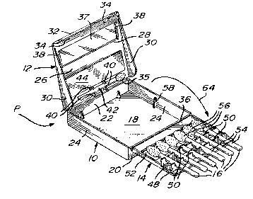
In accordance with the present invention,
Figures 1 to Ç illustrate a cosmetic package P which
basically comprises an open-ended box-like casing
10, a closure 12 pivotally mounted to the casing 10,
and a tray 14 also pivotally mounted to the casing
and adapted for detachably carrying thereon a
series of cosmetic sticks 16. More particularly, as
best seen in Figure 3, the casing 10 includes a
bottom wall 18 of rectangular and almost square
configuration and peripheral walls which extend
upwardly at right angles therefrom and which
include a front wall 20, a rear wall 22, and a pair
of side walls 24 extending parallel between the
front and rear walls 20 and 22.
~,.".,','',.
- 7 - :
-,
.': ' .:."
2~6~g
The closure 12 includes a rectangular or
square wall 26 which is slightly larger than the
transverse dimensions of the casing 10 and which is
pivotally mounted at a rear peripheral edge thereof
to the upper free edge of the rear wall 22 of the
casing 10. The tray 14 is pivotally mounted to the
upper free edge of the front wall 20 of the casing
10. The closure 12 defines a rectangular opening 28
near a front peripheral edge thereof. The main wall
26 of the closure 12 includes a pair of parallel
side walls 30 extending downwardly at right angles
therefrom. A short elongated ledge 3Z extends
downwardly at right angles from the front peripheral ~ -
edge of the main wall 26 of the closure 12. This
ledge 32 defines a pair of inwardly projecting tabs
34. When the tray 14 is in a closed position
(Figures 1, 4 and 6), that is when it is in the
casing 10, the closure 12 can be lowered on the
casing 10 and just above the tray 14 for closing the
cosmetic package P. The pair of tabs 34 of the front
ledge 32 of the closure 12 will engage under the
hinge defined at the pivot of the tray 14 with the
casing 12, with the side walls 30 of the closure 12 -
being disposed laterally on each side of the side
walls 24 of the casing 10.
It is noted that the closure 12 can be
pivotally mounted to any one of the peripheral walls
20, 22 and 24 of the casing 10, with the tray 14
being pivotally mounted to any one of the remaining
peripheral walls thereof. Therefore, the closure 12
and the tray 14 can be pivotally mounted to a pair
of opposite walls of the casing 10 or to a pair of
adjoining walls thereof. ;-
It is also noted that the casing 10, the
closure 12 and the tray 14 are all made of a
plastics material with the pivotal connection
- 8 -
:
.. . .
, . : . . , ,, . . . , : , .: . : .. ~: . :; . , : .:: : : . ... : : .
c~
therebetween being assumed by partly weakened
connections between the integrally joined casing 10,
closure 12 and tray 14. Accordingly, hinges 35 and
36 respectively join the casing 10 with the closure
12 and with the tray 14, as best seen in Figure 5.
The rectangular opening 28 is provided
with a window 37 which is maintained in position by
a pair of short ang~lar flanges or lips 38 (see
Figures 2 to 4) defined along the short longitudinal
edges of the rectangular opening 28. Adjacent the
hinge 35 defined at the junction of the casing 10
with the closure 12, there are provided on the main
wall 26 of the closure 12 two pairs of spaced apart
arms 40 which extend at right angles therefrom
towards the bottom wall 18 of the casing 10 when the
closure 12 is in its closed position, as best seen
in Figures 3 and 5. The pairs of arms 40 are adapted
to remov~bly retain an applicator 42 under the
closure 12. A mirror 44 is adhesively mounted to the
main wall 26 of the closure 12 between the window 37
and the applicator 42 thereof. The mirror 44 can be
used for applying the make-up when the closure is in
its open position.
The tray 14 is pivotally connected to the
upper edge of the front wall 20 of the casing 10 by
the integral hinge 36. Now referring to Figures 3
and 4, the tray 14 includes on its underside (when
considered or viewed in its retracted position in
the casing 10) a pair of parallel elongated members
48 which extend transversely on the tray 14 and at
right angles thereto. The elongated members 48 each
defines a series of spaced apart rectangular notches
50 with each notch of one of the elongated members
48 being longitudinally aligned with a respective
noth of the other one of the elongated member 48.
Accordingly, each pair of aligned notches 50 of the
'::'' ' ' ' .
_ 9 ~
'"' :' ,'
g
elongated members 48 is adapted to removably receive
one of the cosmetic sticks 16 due at least to the
friction forces therebetween.
The tray 14 defines a rectangular opening
52 (see Figure 2) which is of dimensions similar to
those of the rectangular opening 28 and thus of the
window 37 of the closure 12 and which is aligned
therewith when both the tray 14 and the closure 12
are in their respective closiPd positions shown in
Figures 1 and 6. ~ -
As best seen in Figures 3 and 5, the
cosmetic sticks 16 each include an elongated handle
portion 54 of circular cross-section and, at one end
thereof, a head portion 56 consisting of the
cosmetic product intended to be applied by the user.
The cosmetic sticks 16 are removably mounted in the
notches 50 of the elongated members 48 by their
respective handle portion 54 in order that the head
portions 56 thereof are framed within the
rectangular opening 52 of the tray 14, as seen in
Figure 6. Therefore, when the cosmetic package P is
in its closed position illustrated in Figures 1 and
6, the cosmetic coated head portions 56 of the
sticks 16 can be seen through the window 37 of the
closure 12.
As best seen in Figures 3 and 4, in order
to limit the downwards pivot of the tray 14 in the
casing 10, a pair of stoppers 58 extend upwards from
the bottom wall 18 of the casing 10 and near the
middle of the side walls 24 thereof. Therefore, when
the tray 14 is downwardly pivoted in the casing 10,
the longitudinal edges of the tray 14 abut the upper
ends of the stoppers 58, whereby the cosmetic sticks
16 extend substantially parallel between the bottom
wall 18 of the casing 10 and the main wall 26 of the
closure 12 while being spaced therefrom and from the
- 1 0 - .
.: : ., , . .. , . , , ~ . " . ~ . . . . .. . . . .. .
2~ $
tray 14 in order to prevent smearing of the cosmetic
coated head portions 56 of the sticks 16.
The rectangular notches 50 are obviously
sized in accordance with the diameter of the handle
portions 54 of the cosmetic sticks 16.
When the closure 12 is pivoted away from
the casing 10 along the direction of arrows 60 of
Figures 2 and 5, the resiliency in the plastic hinge
36 causes the tray 14 to automatically spring up (as
per arrows 62) in such a way that the longitudinal
side edges thereof and the free rear edge thereof
are no longer encased within the casing 10 thereby
facilitating the further outwards pivot or opening
of the tray 14 (see arrow 64 of Figure 3) with
respect to the casing 10 with a view of retrieving
the cosmetic sticks 16. Resiliency in the hinge 35
which connect the casing 10 to the closure 12 can
also caus'e the closure 12 to spring upwards along
arrow 60 when the tabs 34 are released from
engagement with the ledge 32 of the closure 12.
Figures 6 and 7 illustrate a variant P' of
the cosmetic package P of Figures 1 to 6 in which
the casing lOa incIudes longitudinal side walls 24a
which define a pair of cut-outs 66 for allowin~ the
user to grasp the tray 14a when it is retracted in
the casing lOa thereby facilitatiny its removal
: . .
therefrom (along arrow 68 of Figure 8) in the cases
in which there is no resiliency (or there is a loss
of resiliency) in the hinge 36 to cause the tray 14a ;.
to spring up once the closure 12 is pivo~ed outwards
of the casing lOa. ~:~
Also, the casing lOa of the cosmetic
package P' of Figures 7 and 8 does not include the :.
stoppers 58 of the cosmetic package of Figures 1 to ..
6, whereby the downwards pivot of the tray 14a in .; :
the casing lOa is limited by the ends of the handle ~.~
'.: ;,'~ .
- 1 1 - . ': ~' .
, ':
,~ ', ' . , ,: , '. '; . ., ,; '. ' ~ '.' :. . ',. ',' ' ' : . , ' , .
portions 54 of the cosmetic sticks 16 which abut the
upper surface of the bottom wall 18 of the casing
lOa.
Furthermore, the applicator 42 of the
cosmetic package P' is maintained in position by two
pairs of spaced apart arms 40a which extend upwards
from the upper surface of the tray 14a next to the
rectangular opening 52 thereof.
Now referring to Figure 9, a further
cosmetic package P" in accordance with the present
invention has its applicator 42 retained by two
pairs of spaced apart arms 40b which extend from the
upper surface of the bottom wall 18 of the casing
lOb, with a mirror 70 being disposed on the bottom
wall 18 of the casing lOb. The longitudinal side
walls 24b of the casing lOb of the cosmetic package
P" defines cut-outs 66 such as those of the cosmetic
package P' of Figures 7 and 8.
It is noted that the applicator 42 is
provided in the cases wherein the cosmetic product
which coats the head portions 56 of the sticks 16 is
for application to the eyes. In the cases where the
cosmetic product is intended for the lips or for the
nails, no such applicator 42 is required. Finally,
the window 37 can be clipped to the closure 12, as
described hereinabove by way of the flanges or lips
38, or it can be heat sealed thereto.
Figures 10 to 12 illustrate another
cosmetic package P"' in accordance with the present
invention which is similar to the cosmetic package P
of Figures 1 to 6 although, as illustrated, the
package P"'does not comprise the mirror 44 and the
applicator 42 of package P. As in the cosmetic
package P" of Figure 9, the package P"' includes a
mirror 70c at the bottom of the casing lOc. In any
event, the major differences of the cosmetic package
: ' ,.:'
- 12 -
~. .
: . .
; ~ . ,, . . , . , ,, . . "
P"' of Figures lO to 12 lie in the cosmetic sticks
16c and in the means of attachment thereof to the
tray 14c.
The cosmetic package P"' comprises a casing
lOc with a closure 12c and a tray 14c being hingedly
mounting to upper opposite edges thereof. The
following elements of package P"' are substantially
identical to corresponding features of the cosmetic
package P of Figures l to 6: the front, rear and
side walls 20, 22 and 24 of the casing lOc; the main
wall 26, the opening 28, the pair of side walls 30,
the ledge 32, the tabs 34, the window 37 and the
lips 38, all comprised in the closure 12c; the
hinges 35 and 36 joining the casing lOc respectively
to the closure 12c and to the tray 14c; and the
opening 52 of the tray 14c.
Each cosmetic stick 16c comprises an
elongated handle 54c and a cosmetic-covered head
portion 56 of smaller diameter than the handle 54c.
The handle 54c defines near the head portion 56 a
circumferential annular groove 72c.
The tray 14c comprises a pair of parallel
and spaced apart~elongated members 48c which extend
transversely along the underside of ~he tray 14c
when in its closed position of Figures ll and 12.
Each elongated member 48c defines a series of
notches 50c each having the outline of a circle
missing a~segment, whereby the elongated member 48c
defines adjacent each notch 50c a pair of inwardly
extending arms 74c for clippingly retaining the
handles 54c of the cosmetic sticks 16c in the
notches 50c and thus to the tray 14c. As in the
prior embodiments, the notches 50c of both the
elongated members 48c are disposed longitudinally
opposite one another, whereby each set of facing
notches 50c can hold one of the cosmetic sticks 16c.
, .
- 13 -
., .
L 8
The notches 50c of the elongated member 48c which is
located adjacent the opening 52 of the tray 14c are
smaller than those of the other elongated member 48c
for receiving the annular grooves 72c defined in the
handles 54c of the cosmetic sticks 16c. V-shaped
notches 75c are defined between the stick receiving
notches 50c for allowing some resilient displacement
or flexion of the arms 74c when the cosmetic sticks
16c are snapped onto the tray 14c or are removed
therefro~.
A first elongated support member 76c
extend transversely on the tray 14c between the
opening 52 and the elongated members 48c for
supportiny the cosmetic sticks 16c (and thus
preventing a pivot thereof) at the head portions 56
thereof, that is between the cosmetic which coats
part of each head portion 56 and the handle 54c. A
similar second elongated support member 78c extends
transversely on a bottom wall 18c of the casing ].Oc
for further supporting the cosmetic sticks 16c at a
location on the handles 54c opposite and between the
pair of elongated members 48c when the cosmetic
package is in its closed position. The elongated
members 48c in concert with the first and second
support members 76c and 78c secure the cosmetic
sticks 16c to the tray 14c of the cosmetic package
P"' which, for instance, prevents the smearing in the
casing lOc of the cosmetic provided on the head
portions 56 of the cosmetic sticks 16c.
The second support member 78c defines at
the ends thereof a pair of stoppers 58c which limit
by abutment the downwards pivot of the tray 14c into
the casing lOc and thus prevent the smearing of the
head portions 56 on the bottom wall 18c of the
casing lOc.
- 14 -
2 ~ ~ 6 ~
In all embodiments, an overwrap may cover
the entire closed cosmetic packages to preserve :
freshness of the cosmetic provided on the cosmetic
sticks enclosed therein.
"' ' '
.:
,~
",:
'' . -
- 15 -
.
,~'.
.. . ' . ', ' ~'.', ' ., . ~:. ' ,, , . ,., . , ' .