Language selection

Search

Patent 2106896 Summary

Third-party information liability

Some of the information on this Web page has been provided by external sources. The Government of Canada is not responsible for the accuracy, reliability or currency of the information supplied by external sources. Users wishing to rely upon this information should consult directly with the source of the information. Content provided by external sources is not subject to official languages, privacy and accessibility requirements.

Claims and Abstract availability

Any discrepancies in the text and image of the Claims and Abstract are due to differing posting times. Text of the Claims and Abstract are posted:

  • At the time the application is open to public inspection;
  • At the time of issue of the patent (grant).
(12) Patent: (11) CA 2106896
(54) English Title: WHEEL FAN OF RANGE HOOD
(54) French Title: VENTILATEUR A ROUE DE HOTTE D'EXTRACTION
Status: Expired and beyond the Period of Reversal
Bibliographic Data
(51) International Patent Classification (IPC):
  • F24C 15/20 (2006.01)
  • F04D 29/28 (2006.01)
(72) Inventors :
  • CHIANG, SWEA TONG (Taiwan, Province of China)
(73) Owners :
  • SWEA TONG CHIANG
(71) Applicants :
  • SWEA TONG CHIANG (Taiwan, Province of China)
(74) Agent: SMART & BIGGAR LP
(74) Associate agent:
(45) Issued: 1997-02-25
(22) Filed Date: 1993-09-24
(41) Open to Public Inspection: 1995-03-25
Examination requested: 1993-11-16
Availability of licence: N/A
Dedicated to the Public: N/A
(25) Language of filing: English

Patent Cooperation Treaty (PCT): No

(30) Application Priority Data: None

Abstracts

English Abstract


The present invention relates to a wheel fan of a range
hood used in the kitchen having improved blades and
mechanisms for locating a top plate, which comprises blades,
top plate sinking inwardly like a bowl, a bottom ring, convex
rings set at the side and top of the blades, and cahnnels
formed on the top plate and bottom ring which match the
convex rings, so that assembly will be simplified,
performance be reliable and noise be less.


Claims

Note: Claims are shown in the official language in which they were submitted.

WHAT IS CLAIMED IS:
A wheel fan of a range hood having improved blades and
mechanisms for locating a top plate, which comprises blades,
a top plate sinking inwardly like a bowl, a bottom ring and
convex rings set at the side and top of the blades;
characterized in that: at least one convex ring is provided
on the top or side of the blades, and there are channels
formed on the top plate and bottom ring conrresponding to the
said convex rings.

Description

Note: Descriptions are shown in the official language in which they were submitted.


21Q6896
WHEEL FAN OF RANGE HOOD
BACKGROUND OF THE lNV ~'N'l'ION
Field of the Invention:
The present invention relates a wheel fan of a range
hood used in the kitchen and particularly to a wheel fan of a
ventilator having improved blades and mechanisms for locating
a top plate.
Description of the Prior Art:
The wheel fan of a conventional range hood, as shown in
Fig. 1, has a top cover 100A concave at its center like a
bowl; rectangular blades 200A ranging radially and held by
the top cover 100A; a plane circular bottom plate 300A
conncected to the bottom of the blades 200A; and centrifugal
blades 400A held by a central hole on the bottom plate 30OA.
It performs badly and makes much noise.
The wheel fan of a conventional range hood developed
later, as shown in Fig. 2, has a top plate 100B sinking
inwardly, a bent bottom ring 300A, and blades 200B held by
the top plate 100B and bottom plate 300B. Because the blades
200B are independent, they are connected to the bottom ring
300B and then the top plate 100B one by one, so that assembly
is laborious. Furthermore, the performance is unstable due to
a change of the distance between any two adjacent blades.
SUMMARY OF THE lN V ~:N~l~IoN
It is an object of the present invention to provide a
wheel fan of a range hood which has a constant distance
between any two adjacent blades, firm fixation, and as a

210~96
result of a reliable performance.
This wheel fan has improved blades and mechanisms for
locating a top plate, which comprises blades, a top plate
sinking inwardly like a bowl, a bottom ring, and convex rigns
set at the side and top of the blades; characterized in that:
the convex rings match channels formed on the top plate and
the bottom ring.
A more complete understanding of these and other
features and advantages of the present invention will become
apparent from a careful consideration of the following
detailed description of certain embodiments illustrated in
the accompanying drawings.
BRIEF DESCRIPTION OF THE DRAWINGS
In the accompanying drawings:
Fig. 1 is a schematic view of a conventional wheel fan
of a range hood;
Fig. 2 is a schematic view of another embodiment of a
conventional wheel fan of a range hood;
Fig. 3 is a separated view of Fig. 2;
Fig. 4 is a separated view of the first embodiment of
the present invention;
Fig. 5 is a separated view of the second embodiment of
the present invention;
Fig. 6 is a separated view of the third embodiment of
the present invention;
Fig. 7 is a separated view of the fourth embodiment of
the present invention;

210fi8~
Fig. 8 is a separated view of the fifth embodiment of
the present invention;
Fig. 9 is a cross-sectional view of Fig. 4 and Fig. 5;
Fig. 10 is a cross-sectional view of Fig. 6;
Fig. 11 is a cross-sectional view of Fig. 7; and
Fig. 12 is a cross-sectional view of Fig. 8.
DESCRIPTION OF THE PREFERRED EMBODIMENTS
A wheel fan of a range hood used in the kitchen having
improved blades and mechanisms for locating a top plate
comprises a wheel 1, a bottom ring 13 and a top plate 2.
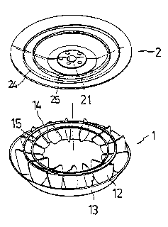
Referring to Fig. 4 (the first embodiment), a wheel
has a number of blades 12. The blades 12 and the bottom ring
13 are casted in metallic or plastic materials as a body.
Convex rings 14, 15 are set at the top of the blades 12. the
shape of the top plate 2 is like a bowl, wherein an axial
hole 21 is formed at the center to penetrate a motor pivot.
Two channels 24, 25 are formed on the top plate 2 to embed
to convex rings 14, 15 therein; then the wheel 1 is joined
with the top plate 2 as a body by means of point welds or
high periodic waves. The resultant wheel fan has simple
assembly, reliable performance and less noise.
Referring to Fig. 5 (the second embodiment), the wheel 1
is joined with the bottom ring 13 or the top plate 2 by means
of embedding ear pieces 12A, 12B formed at the side and the
top of the blades 12 into holes 13A, 2A which are separately
formed on the bottom ring 13 and the top plate 2. This joint
is easy because of the fixed blades 12, and the matching
between the convex rings 14, 15 and the channels 24, 25.

~ Ofi89~
-
Referring to Fig. 6 (the third embodiment), channels 24,
25, 26, 27 are formed on the top plate 2 and the bottom ring
13 separately, and convex rings 14, 15, 16, 17 are set at the
side and top of the blades 12. The blades 12 are joined to
the convex rings 14, 15, 16, 17 as a body by means of point
welds or high periodic waves. The resultant wheel is then
joined with the bottom ring 13 and the top plate 2 by means
of embedding the convex rings 14, 15, 16, 17 separately into
the channels 24, 25, 26, 27 and then using point welds and
high periodic waves. The resultant wheel fan also has simple
assembly, reliable performance and less noise.
Referring to Fig. 7 and Fig. 8 (the fourth and fifth
embodiments), convex rings are set according to the force
beared by the wheel fan. Maybe there are only two convex
rings 14, 16 set at the top and side of the~blades 12 as
shown in Fig. 7, or only one convex ring 16 set at the bottom
of the blades 12 as shown in Fig. 8.

Representative Drawing
A single figure which represents the drawing illustrating the invention.
Administrative Status

2024-08-01:As part of the Next Generation Patents (NGP) transition, the Canadian Patents Database (CPD) now contains a more detailed Event History, which replicates the Event Log of our new back-office solution.

Please note that "Inactive:" events refers to events no longer in use in our new back-office solution.

For a clearer understanding of the status of the application/patent presented on this page, the site Disclaimer , as well as the definitions for Patent , Event History , Maintenance Fee  and Payment History  should be consulted.

Event History

Description Date
Inactive: IPC from MCD 2006-03-11
Time Limit for Reversal Expired 2003-09-24
Letter Sent 2002-10-22
Inactive: Late MF processed 1997-10-24
Letter Sent 1997-09-24
Grant by Issuance 1997-02-25
Application Published (Open to Public Inspection) 1995-03-25
All Requirements for Examination Determined Compliant 1993-11-16
Request for Examination Requirements Determined Compliant 1993-11-16

Abandonment History

There is no abandonment history.

Fee History

Fee Type Anniversary Year Due Date Paid Date
Reversal of deemed expiry 2001-09-24 1997-10-24
MF (patent, 4th anniv.) - small 1997-09-24 1997-10-24
MF (patent, 5th anniv.) - small 1998-09-24 1998-06-01
Reversal of deemed expiry 2001-09-24 1998-06-01
MF (patent, 6th anniv.) - small 1999-09-24 1999-07-20
Reversal of deemed expiry 2001-09-24 2000-08-18
MF (patent, 7th anniv.) - small 2000-09-25 2000-08-18
MF (patent, 8th anniv.) - small 2001-09-24 2001-09-05
Reversal of deemed expiry 2001-09-24 2001-09-05
Owners on Record

Note: Records showing the ownership history in alphabetical order.

Current Owners on Record
SWEA TONG CHIANG
Past Owners on Record
None
Past Owners that do not appear in the "Owners on Record" listing will appear in other documentation within the application.
Documents

To view selected files, please enter reCAPTCHA code :


To view images, click a link in the Document Description column. To download the documents, select one or more checkboxes in the first column and then click the "Download Selected in PDF format (Zip Archive)" or the "Download Selected as Single PDF" button.

List of published and non-published patent-specific documents on the CPD .

If you have any difficulty accessing content, you can call the Client Service Centre at 1-866-997-1936 or send them an e-mail at CIPO Client Service Centre.


Document
Description 
Date
(yyyy-mm-dd) 
Number of pages   Size of Image (KB) 
Cover Page 1995-06-03 1 40
Drawings 1995-06-03 6 226
Abstract 1995-06-03 1 27
Claims 1995-06-03 1 24
Description 1995-06-03 4 183
Cover Page 1997-02-20 1 12
Drawings 1997-02-20 6 131
Claims 1997-02-20 1 15
Description 1997-02-20 4 128
Abstract 1997-02-20 1 14
Representative drawing 1999-07-12 1 12
Maintenance Fee Notice 1997-10-23 1 178
Late Payment Acknowledgement 1997-11-04 1 171
Maintenance Fee Notice 2002-10-22 1 175
Fees 1997-10-24 2 58
Fees 1996-08-12 1 43
Fees 1995-08-01 1 46
Prosecution correspondence 1993-11-16 2 43
Courtesy - Office Letter 1994-04-18 1 62
Prosecution correspondence 1996-06-10 1 22
PCT Correspondence 1996-12-09 2 48
Examiner Requisition 1996-03-01 2 60