Note: Descriptions are shown in the official language in which they were submitted.
Process and apparatus for the preparation of a poly-
urethane reaction mixture
This invention relates to a process and an apparatus for
the preparation of a polyurethane reaction mixture from
flowable reactants and an additive, in particular a
blowing agent, in which the streams of reactants are
metered into a mixing zone and the additive is metered
into one of the streams of reactants, as disclosed in
DE-B-1 153 153 (corresponding to GB-B-957 748).
According to DE-B-1 128 125 (corresponding to US-A-
3 230 047), blowing agent is absorbed by a pump and
metered into a premixer where it is premixed with the
polyol component. Owing to the low viscosity of blowing
agents and their low boiling points, such pump systems
require high input pressures at the inlet end, but these
high pressures cause external leakages into the surround-
ings. Closed pump systems such as membrane pumps are not
suitable owing to their pulsating delivery.
According to DE-B-1 153 153 (corresponding to GB-B-
957 748), the procedure may be the same as described
above. The apparatus shown there may have a modification
(which, however, is not explicitly described there) so
that the polyol component is taken in by a fore pump and
Le A 28 240 2
210'~2,~
metered into a premixer into which the blowing agent is
also introduced, and the resulting mixture is taken in by
a main pump and delivered into a mixing head. ~f one
operated in this manner, fluctuations in pressure in the
supply system would cause considerable variations in the
quantity of blowing agent delivered so that the mixing
ratio would be completely falsified and the properties of
the end product would be deleteriously affected.
The problem arises of providing a process and an apparatus
with which even small quantities of flowable additives, in
particular blowing agents, can be introduced without
leakage and in the correct quantity or with only neglig-
ible deviations even in the event of pressure fluctuations
in the supply system.
To solve this problem, the stream of reactant which is to
be charged with additive is subdivided into a main stream
and a side stream which is branched off in a measured
quantity and the additive is introduced into this metered
side stream, and the side stream charged with additive is
reunited with the main stream.
The additive is preferably introduced by pump intake
together with the reactant of the side stream. Due to the
metered introduction of the additive into a side stream,
the fluctuations in delivery rate can be kept all the
smaller the lower the delivery rate of reactant in the
side stream compared with that of the main stream.
According to a particular embodiment of the new process,
the delivery rate of reactant in the side stream is
therefore kept substantially smaller than that of the main
stream, preferably at most 10%.
Le A 28 240 3 ""
2~.~'~
For the preparation of a polyurethane reaction mixture,
the additive is introduced into the more highly viscous
polyol component, as is usual, if this additive 'has a
lower viscosity than the polyol, which is generally the
case with blowing agents. More highly viscous additives
are preferably introduced, into the more fluid isocyanate
component.
According to a particular embodiment, additive and
reactant are homogeneously mixed in the side stream.
According to another embodiment of the process, the side
stream charged with additive is homogeneously mixed with
the main stream.
This may take place in addition to the homogenisation of
the side stream. This preliminary mixing has a favourable
effect on the subsequent course of the reaction between
the two reactants.
The new apparatus for the preparation of a polyurethane
reaction mixture of flowable reactants and an additive, in
particular a blowing agent, is based on storage containers
for reactants and a storage container for additive with
pipes leading from the storage containers for reactants to
a mixing head via first dosing pumps and a supply pipe for
blowing agent leading from the storage container for
additive and opening into the supply pipe for the reactant
charged with additive, as disclosed in DE-B-1 153 153
(corresponding to GB-B-957 748).
The novelty is to be seen in the fact that this supply
pipe which contains the first dosing pump is branched into
a main pipe and a side pipe, that a second dosing pump and
a third dosing pump are arranged in the side pipe ahd the
Le A 28 240 4
supply pipe for additive opens between this seCOnd and
third dosing pump, that the third dosing pump has a
delivery rate which is higher than that of the second
dosing pump by the quantity of blowing agent to be
supplied, and that the side pipe rejoins the main pipe
downstream of the third dosing pump.
This arrangement enables the delivery rate of additive to
be kept substantially constant even in the event of
pressure fluctuations in the delivery system or enables
deviations in the quantitative ratio to the reactant which
is to be charged to be kept negligible. There is no risk
of leakages to the outside even when commercially
available piston dosing pumps are used since the additives
are not delivered on their own but together with the
reactant by only one dosing pump. The additional technical
expenditure is small compared with the improvement in
quality of the end product.
According to one particular embodiment, the output of the
second dosing pump is substantially smaller than that of
the first delivery pump, preferably amounting to at most
10% of the latter.
According to another particular embodiment of the
apparatus, the first dosing pump is arranged in the supply
pipe before it branches into the main pipe and the side
pipe.
In that case, the first and the second dosing pump are
arranged in series and the first dosing pump absorbs the
total quantity of reactant required from the storage
container which is generally at an inlet pressure of from
2 to 4 bar. The side stream is then separated off from
this main stream by means of the second dosing' pump
Le A 28 240
~~~rl?li,~;
arranged in the side pipe, and this side stream is then
absorbed together with the additive by the third dosing
pump.
Alternatively, the first dosing pump may be arranged in
the main pipe.
In that case, the first and the second dosing pump operate
in parallel so that the sum of their delivery rates is
equal to the total delivery rate of reactant. The mode of
operation is otherwise the same as in the first embodi
ment.
A mixer is preferably arranged in the side pipe behind the
opening of the supply pipe for additive.
The additive is thereby homogeneously distributed in the
reactant. The mixer may be arranged in front of or
behind the third dosing pump.
According to another particular embodiment, a mixer is
arranged in the supply pipe for reactant behind the point
at which the main pipe is united with the.side pipe.
In this case the additive may again be homogeneously
distributed in the stream of reactant.
Two exemplary embodiments of the new apparatus are
described below with reference to~the drawing, which is a
purely schematic flow diagram, and: in which
Fig.l shows an apparatus according to the first
exemplary embodiment and
Le A 28 240 6
2:~~7.',',~
Fig.2 shows an apparatus according to the second
exemplary embodiment.
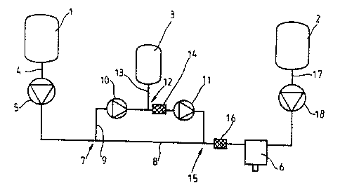
In Fig.l, the apparatus comprises a storage container 1
for polyol as reactant, a storage container 2 for
isocyanate as reactant and a storage container 3 for a
blowing agent as additive. A supply pipe 4 leads from the
storage container 1 to a mixing head 6 by way of a first
dosing pump 5. Downstream of the first dosing pump 5, the
supply pipe 4 branches at 7 into a main pipe 8 and a side
pipe 9. The side pipe 9 contains a second dosing pump 10
and a third dosing pump 11 between which two pumps is the
opening 12 of a pipe 13 leading from the storage container
3 for additive., Downstream of the opening 12, a mixer 14
is provided _in the side pipe 9. The side pipe 9 and the
main pipe 8 rejoin at 15. Downstream of this point, the
pipe 4 contains a static mixer 16.~A supply pipe 17 leads
from the storage container 2 to the mixing head 6 by way
of a dosing pump 18.
The apparatus shown in Fig.2 consists of a storage
container 21 for polyol as reactant, a storage container
22 for isocyanate as reactant and a storage container 23.
for a blowing agent.as additive. A pipe 24 leads from the
storage container 21 to a mixing head 26. This pipe
branches at 27 into a main pipe 28 and a side pipe 29. A
first dosing pump 25 is arranged in the main pipe 28;
a second dosing pump 30 and a third dosing pump 31 are
provided in the side pipe 29. A pipe 33 leading from the
storage container 23 for additive opens into the pipe 29
at 32 between the second and third dosing pump. A mixer 34
is also arranged in the side pipe 29, downstream of the
opening 32. The main pipe 28 and the side pipe 29 reunite
at 35. A static mixer 36 is provided downstream of the
point 35 in the pipe 24. A pipe 37 leads from the storage
Le A 28 240 7
2~0'~?~~
container 22 to the mixing head 26 by way of a dosing pump
38.
The mode of operation of the apparatus shown in Fig.l is
as follows: The storage containers 1,2 and 3 are under an
inlet pressure of 3 bar. The dosing pump 5 delivers
polyol at the rate of 5000 g/min. 150 g/min of this
quantity are branched off into the side pipe 9 by the
dosing pump 10. The remaining 4850 g/min flow through the
main pipe 8. The dosing pump 11 operates at an output
rate of 300 g/min so that it takes in 150 g/min of blowing
agent in addition to the stream of 150 g/min of component
provided by the dosing pump 10. The ratio of polyol to
blowing agent is therefore 100 parts by weight to 3 parts
by weight. The blowing agent is finely distributed in the
polyol~ in the mixer 14. In the mixer 16, the side stream
charged with blowing agent is homogenized with the main
stream. The dosing pump 18 delivers 5000 g/min of
isocyanate to the mixing head 6. Both delivery systems are
under a pressure of 100 bar.
If, for example, a rise in pressure to 120 bar occurs at
the polyol side, this is associated with a reduction in
delivery rate of about 2%, i.e. dosing pump 5 changes its
delivery rate from 5000 to 4900 g/min and dosing pump 11
changes its delivery rate from 300 to 294 g/min.
The delivery rate of pump 10 remains constant at 150 g/min
as there is no change in its counter pressure. The fall in
delivery rate of blowing agent is only 6 g/min, in other
words 144 g/min of blowing agent continue to be delivered.
The ratio of polyol to blowing agent is 100 parts by
weight to 2.94 parts by weight.
The mode of operation of the apparatus shown in Fig.2 is
as follows: The storage containers,21,~2 and,Z,3 are under
Le A 28 240 8
4
an inlet pressure of 4 bar. Dosing pump 25 delivers 4850
g/min of polyol through the main pipe 28 and dosing pump
30 delivers 150 g/min of polyol through the side pipe 29.
Dosing pump 31 operates at a delivery rate of 300 g/min so
that in addition to the stream of component provided by
the dosing pump 30 it takes in 150 g/min of blowing agent.
The ratio of polyol to blowing agent is therefore 100
parts by weight to 3 parts by weight. The blowing agent is
finely distributed in the polyol in the mixer 34. In the
mixer 36, the side stream charged with blowing agent is
homogenized with the main stream. The dosing pump 38
delivers 5000 g/min of isocyanate to the mixing head 26.
Both delivery systems are under a pressure of 100 bar.
When a pressure rise to 120 bar occurs at the polyol side,
this is associated with a decrease in delivery rate of
about 2%. The dosing pump 25 then delivers only 4753
g/min. The dosing pump 30 remains constant at 150 g/min
and the dosing pump 31 delivers 294 g/min, i.e. 6 g/min
less of blowing agent. The total delivery rate of polyol
is 4903 g/min and of blowing agent 144 g/min, i.e. 2.94
parts by weight of blowing agent are delivered for every
100 parts by weight of polyol
If the apparatus according to DE-B-1 153 153 (correspond-
ing to GB-B-957 748) is employed according to the
variation mentioned at the beginning, which has not been
described in detail, the stream of golyol of 5000 g/min is
supplied with 150 g/min of blowing agent when the mixing
pump is adjusted to a delivery rate of 5150 g/min. The
system pressure is 100 bar. The ratio of polyol to blowing
agent is 100 parts by weight to 3 parts by weight. A rise
in pressure to 120 bar is associated with a decrease in
delivery rate of 2%, i.e. the mixing pump then delivers
only 5047 g/min. The decrease in delivery rate of
103 g/min is entirely at the expense of blowing'agent
Le A 28 240 g
21~7~40
while the polyol continues to be delivered in the correct
quantity by the fore pump so that only 47 g/min of blowing
agent are now introduced. The ra~~io of polyol to bowing
agent breaks down completely and is only 100 parts by
weight to 0.94 parts by weight.
The numerical examples given here in [g/minJ apply
accurately only if the polyol and the blowing agent have
the same specific gravity.
Le A 28 240 10