Language selection

Search

Patent 2107522 Summary

Third-party information liability

Some of the information on this Web page has been provided by external sources. The Government of Canada is not responsible for the accuracy, reliability or currency of the information supplied by external sources. Users wishing to rely upon this information should consult directly with the source of the information. Content provided by external sources is not subject to official languages, privacy and accessibility requirements.

Claims and Abstract availability

Any discrepancies in the text and image of the Claims and Abstract are due to differing posting times. Text of the Claims and Abstract are posted:

  • At the time the application is open to public inspection;
  • At the time of issue of the patent (grant).
(12) Patent: (11) CA 2107522
(54) English Title: TEMPERATURE RESPONSIVE 3-WAY LINE VALVE WITH SHAPE MEMORY ALLOY ACTUATOR
(54) French Title: ROBINET THERMOSTATIQUE A TROIS VOIES POSSEDANT UN ACTIONNEUR EN ALLIAGE A MEMOIRE DE FORME
Status: Term Expired - Post Grant Beyond Limit
Bibliographic Data
(51) International Patent Classification (IPC):
  • F16K 31/70 (2006.01)
  • G05D 23/13 (2006.01)
(72) Inventors :
  • PERLMAN, MAIER (Canada)
  • BELL, JAMES M. (Canada)
  • MARTIN, RICHARD L. (United States of America)
  • MCGUGAN, COLIN A. (Canada)
(73) Owners :
  • MAIER PERLMAN
  • JAMES M. BELL
  • RICHARD L. MARTIN
  • COLIN A. MCGUGAN
(71) Applicants :
(74) Agent: SMART & BIGGAR LP
(74) Associate agent:
(45) Issued: 1997-12-30
(22) Filed Date: 1993-10-01
(41) Open to Public Inspection: 1994-09-05
Examination requested: 1993-10-01
Availability of licence: N/A
Dedicated to the Public: N/A
(25) Language of filing: English

Patent Cooperation Treaty (PCT): No

(30) Application Priority Data:
Application No. Country/Territory Date
026,032 (United States of America) 1993-03-04

Abstracts

English Abstract


The invention provides a self-contained automatic
temperature-responsive three way line valve. A tubular valve
member is axially slidable between first and second limit
positions for selectively directing fluid from an inlet port
to a first outlet port or a second outlet port. The valve
member is disposed between a pair of opposed compression
springs, one being a conventional spring biasing the valve
member to the first limit position and the other being an SME
spring which overcomes the bias of the first-mentioned spring
when the fluid exceeds a given temperature.


French Abstract

Vanne automatique à trois voies sensible à la température. Un élément de robinetterie tubulaire glisse dans le sens axial entre les première et deuxième position de fin de course pour acheminer le fluide d'un orifice d'entrée vers un premier ou un deuxième orifice de sortie. L'élément de robinetterie est placé entre deux ressorts de pression opposés, l'un étant un ressort classique qui pousse l'élément de robinetterie à la première position de fin de course et l'autre étant un ressort à effet mémoire qui surpasse le premier ressort si le fluide dépasse une température donnée.

Claims

Note: Claims are shown in the official language in which they were submitted.

- 7 -
WE CLAIM:
1. A temperature-responsive three-way line valve
comprising:
a tubular valve body defining an internal chamber,
the valve body providing an inlet port communicating with
said internal chamber, and first and second outlet ports,
a tubular valve member slidably mounted within the
valve body for axial movement between first and second limit
positions, said valve member in its first limit position
closing communication between the inlet port and the second
outlet port, and in its second limit position closing
communication between the inlet port and the first outlet
port,
a first compression spring biasing the valve member
towards its first limit position and a second compression
spring opposing said first compression spring biasing the
valve member towards its second limit position,
the second compression spring being of a shaped
memory effect (SME) alloy and having a stiffness which in the
martensitic state of the alloy, is insufficient to overcome
the bias of the first compression spring whereby the valve
member is retained in said first position, and having a
stiffness which, in the austenitic state of the alloy,
overcomes the bias of the first compression spring thereby to
urge the valve member to said second position.
2. A temperature-responsive three-way line valve
according to claim 1, wherein the second compression spring
is disposed adjacent to the inlet port.

- 8 -
3. A temperature-responsive three-way line valve
according to claim 2, wherein the second compression spring
is a helical coil spring positioned to induce turbulent flow
of fluid entering to the inlet port.
4. A temperature-responsive three-way line valve
according to claim 3, wherein the valve body provides an
internally directed retaining flange carrying a thermally
insulating pad against which one end of the second
compression spring bears thereby to minimize heat transfer
between the compression spring and the valve body.
5. A temperature-responsive three-way line valve
comprising:
a tubular valve body defining an internal chamber,
the valve body providing an inlet port at one end of the
valve body, a first outlet port at the other end of the valve
body, the inlet port and said first outlet port being axially
aligned, and a second outlet port communicating with said
chamber at a position between said inlet port and first
outlet port,
a tubular valve member slidably mounted within the
valve body for axial movement between first and second limit
positions, said valve member in its first limit position
closing communication between the inlet port and the second
outlet port, and in its second limit position closing
communication between the inlet port and the first outlet
port,
the valve body providing internal abutment means
engageable with one end of the valve member for defining said
first limit position of the valve member,
a spider assembly located within the valve body, the

- 9 -
spider assembly being engageable with the other end of the
valve member for defining the second limit position thereof,
a first compression spring biasing the valve member
towards its first limit position and a second compression
spring opposing said first compression spring biasing the
valve member towards its second limit position,
the second compression spring being of a shaped
memory effect (SME) alloy and having a stiffness which in the
martensitic state of the alloy, is insufficient to overcome
the bias of the first compression spring whereby the valve
member is retained in said first position, and having a
stiffness which, in the austenitic state of the alloy,
overcomes the bias of the first compression spring thereby to
urge the valve member to said second position.
6. A temperature-responsive three-way line valve
according to claim 5, wherein the valve body provides an
internally directed retaining flange carrying a thermally
insulating pad against which one end of the second
compression spring bears thereby to minimize heat transfer
between the compression spring and the valve body.
7. A temperature-responsive three-way line valve
according to claim 6, wherein the spider assembly comprises
a spider support member having an imperforate central portion
and a perforate peripheral portion defining a flow passage
communicating with the first outlet port, and a retainer
member mounted on said central portion of the support member,
the retainer member supporting one end of the first
compression spring, and the central portion cooperating with
one end of the valve member in the second position of the
valve member to close said flow passage.
8. A temperature-responsive three-way line valve

- 10 -
according to claim 7, wherein the retainer member is mounted
on said central portion of spider support member by
adjustment means for adjusting the bias of said first
compression spring.

Description

Note: Descriptions are shown in the official language in which they were submitted.


2~7~22
Field of the I~vQntion
The present invention relates to temperature~
responsive, thrcc ~_y line valves, such valv~s being commonly
u~ed in fluid supply line~ to direct fluid selectively to one
or other of two outlets dep~n~;n~ on the fluid temperature.
Backqround of the InVP~t;~n
In a syste~ in which a fluid is required to be
supplied at a given controlled tr _.atuLe, a thrcc li~y line
valve may be used to divert the fluid to a heat Px~h~n~r or
other device if its temperature differs from the required
tempe~aLu~. If the tempeL~Lu,e is within the required
supply range, the fluid is directed strai~ht to the end use.
For example, if the fluid is too hot, the valve will be used
to divert it to a heat P~rhAn~er for cooling; similarly, if
the fluid is too cold, the valve will be used to divert it to
a heater.
Prese~t system~i of the kind referred to use
electrically or ~ tically OPeLCLed valves controlled by
separate t2mperature Se~80L~. Such valves are not sQlf-
contained but ~epend on external ~ ~ ants and an external
power supply for their control.

--' 21~7522
- 2
Sl Y of the Invention
The present invention provides a temperature~
responsive thrEc ~_y line valve which is r~ielf-contained, fast
acting, and operable automatically independently of external
power.
''~ ;: ~'.'..'
Briefly, a valve according to the invention comprise~
a t~lh~lAr valve body defining an internal cham~er, the i~ody
providing an inlet port and first and s-con~ outlet ports
which can be placed selectively in c- -ication with the
inlet port by means of a tubular valve mamber slidably
mounted within the valve body for axial ~vl t between
first and second limit positions. In the first limit
position of the valve member, communication between the inlet
port and the second outlet port is closed, while in the
.s~cQn~ limit position of the valve m~mber, communication
b~L.~ee~i~ the inlet port and the first outlet port i~ closed.
The valve member is disposed between two opposing biasins
springs, one of which i~ of shi~re~ y effect tSME) alloy
and of such a stiffness that, in the martensitic state of he
alloy, its stiffness is uve~- ~ by the opposing spring and
the valve member is ret~~n~ in the first limit position
while, in the austenitic state of the alloy, it ova-~ ~~ the
bias of the opposing spring to urge the valve member to the
secon~ limit poQition.
Since the state of the alloy changes from martensitic
to austenitic, or vice versa, at a given temperature, the
valve e is automatically switched between the two limit
positions when the given temperature is r
Brief Descri~tion of the Drawinqs
In order that the invention may be readily
understood, a preferred ~ ~ L thereof will now be

7~22
- 3 -
de~cri~ed by way of example with reference to the
~ nying drawings, in which~
, ::
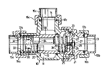
Figure 1 is a composite longit~ n~l sectional view
of a temperature-responsive thrcc ~.ay valve according to the
invention, the view being divided horizontally along the axis
of the vaLve to show the valve - .r in each of it~ two
limit positions;
Figure 2 is an end view of the valve - - taken on
line 2-2 in Figure 1; and
Figure 3 is an end view of the spider assP~bly taken
on line 3-3 in Figure 1.
DescriPtion of the Preferred r --~i L
Referring to Figure 1, the valve comprise~ a t~h~ r
valve body 10 defining an internal chamber 11, the valve body
providing an inlet port 12 at one end of the valve body, a
first outlet port 13 at the other end of the valve body in
axial ali3 L with the inlet port, and a secon~ outlet port
14 communicating with the valve chamber 11 at a position
between the inlet port 12 and the outlet port 13. Tube or
pipe adaptors 15a, 15b, 15c are attached to the valve body 10
at each of the ports 12, 13, 14 by threaded nuts 16a, 16b,
16c. Seals 17a, 17b, 17c retained in mating yLo~va~ are
provided at the inlet and outlet ports to prevent external
le~k~qe of fluid.
A t~h~ r valve - ~~r or shuttle 18, is slidably
mounted within the bore of the valve body 10 for
reciprocatory axial -v. - ~ between first and second limit
positions, the first limit position being shown in the upper
half of Figure 1 and the second limit position being shown in
the lower half of Figure 1. The valve member 18 has a
: .
"' .' '
. .~ .

5 2 2
- 4 -
cylindrical wall formed with an annular step 19 which, in thefixst limit position of the valve member, eny~yes an internal
abui --t edge 20 of the valve ibody, thus defining said first
limit position.
A spider assembly 21 is located within the valve body
10 on the downstream side of the valve member 18. The ~pider
assembly 21 comprises a ~u~olL member having an imperforate
central portion 22 and a perforate peripheral portion ~3
providing slots 24 (shown in Figure 3) which permit the
pAc~i~ge of fluid from the valve rh ~?r 11 to the first
outlet port 13. Th~ second limit position of the valve
member 18 is defined by a peripheral abutment edge 25 of the
central portion 22 of the spider assembly which is aligned
with, and engageable with, the downstream edge of th~ valve
~ - 18 as shown in the lower half o~ Figure 1. A retainer
plate or member 26 is mounted on tha central portio~ 22 of
the spider ~u~o.L member, roAYi~ y with it, by means of an
adju~tment screw 27 carrying a lock nut 28.
The valve member 18 is ~ ose~ between a pair of
oppose~ helical compression spring~ 29, 30. The first
_ _ession spring 29 is a cui.vel.Lional spring xu~orLed and
constrained at one end by the retainer 'er 26, the other
end of the spring engaging a~ internal abutment step 31 of
the tubular valve me~ber 18 thereby biasing the valve member
towards the first limit position shown in the upper hal~ of
Figure 1. It will be ob~erved that, when the valve ~- is
in this first limit positlon, -- 1cation between the inlet
port 12 and the secon~ outlet port 14 is clo ed, but fluid
can flow from the inlet port 12 to the first outlet port 13
via the tubular valve member 18 and the spider slots 24.
The second compression spring 30 is o~ SME alloy
which, when cold, is in the martensitic state but which
changes to the austenitic state when heated to given

~'' 21~752~
- 5 -
temperature depending on the composition and processing of
the alloy. When the alloy is in the martenYitic state it
exhibits a low modulus of elasticity, and when it is in the
auqtenitic state it has a high modulus of elasticity. The
tiffneg8 of the first compression spring 29 is therYfore
chosen to be greater than that of the compre~ion spring 30
when the latter is at a temperature lower than the tran~ition
temperature, but less than that of the compression spring 30
when the temperature of the latter e~cee~c the transition
temperature.
In operation, when ~he fluid flowing through the
valve is at a temperature less than a given temperature, i.e.
the tran~ition tempe~aLu.e, the valve member is in the first
limit position, i.e. the "cold position" shown in the upper
hal~ of Figure 1, the valve - er being seated by engagement
of the annular step 19 with the internal abutment edge 20.
Fluid then ~lows from ~he inlet port 12, past the comprPssion
spring 30, through the inside o~ the t~hnl~r valve member 18,
through the open coils of the compres ion spring 29, and
through the spider slots 24 to the first outlet port 13. The
secon~ outlet port 14 L ~ I nC clo~ed.
When the fluid is heated to a given temperature, the
compression spring 30 becomes more rigid so that the biasing
spring 29 can no longer overcome the bias of the spring 30;
therefore the valve ~-r is moved rapidly to its second
limit position shown in the lower half Of Figure 1. In this
position fluid will flow from the inlet port to the se~nn~
outlet port 14 via slots 34 at one end of the valve member.
The temperature at which the valve member 18 will be
switched between the two limit positions can be adjusted by
the adjustment screw 27, thereby to adjust the bias exerted
by the first compression spring Z9.

2~ ~7~2~
-- 6 --
It will be seen that the SME spring 30 is located in
an axial bore of the valve body 10, and is retained by an
inwardly directed flange 32 of the valve body. The u~sL-eam
end of the SME spring bears on a ~h~ -~ly insulating pad 33
mounted on the flange 32 for insulating the SME spring from
the valve body. An important feature of the valve is that
the SME spring, being a helical coil spring, is located in
the axial bore adjacent to the inlet port 12 so as to induce
turbulence in the ; nl~ - n~ fluid and there~y ~nhAnc~ heat
trans~er between the fluid and the spring.

Representative Drawing
A single figure which represents the drawing illustrating the invention.
Administrative Status

2024-08-01:As part of the Next Generation Patents (NGP) transition, the Canadian Patents Database (CPD) now contains a more detailed Event History, which replicates the Event Log of our new back-office solution.

Please note that "Inactive:" events refers to events no longer in use in our new back-office solution.

For a clearer understanding of the status of the application/patent presented on this page, the site Disclaimer , as well as the definitions for Patent , Event History , Maintenance Fee  and Payment History  should be consulted.

Event History

Description Date
Inactive: Expired (new Act pat) 2013-10-01
Inactive: IPC from MCD 2006-03-11
Grant by Issuance 1997-12-30
Pre-grant 1997-09-19
Inactive: Final fee received 1997-09-19
Notice of Allowance is Issued 1997-08-14
Letter Sent 1997-08-14
Notice of Allowance is Issued 1997-08-14
Inactive: Status info is complete as of Log entry date 1997-08-11
Inactive: Application prosecuted on TS as of Log entry date 1997-08-11
Inactive: IPC assigned 1997-07-23
Inactive: IPC removed 1997-07-23
Inactive: First IPC assigned 1997-07-23
Inactive: Approved for allowance (AFA) 1997-07-21
Application Published (Open to Public Inspection) 1994-09-05
All Requirements for Examination Determined Compliant 1993-10-01
Request for Examination Requirements Determined Compliant 1993-10-01

Abandonment History

There is no abandonment history.

Maintenance Fee

The last payment was received on 1997-07-18

Note : If the full payment has not been received on or before the date indicated, a further fee may be required which may be one of the following

  • the reinstatement fee;
  • the late payment fee; or
  • additional fee to reverse deemed expiry.

Please refer to the CIPO Patent Fees web page to see all current fee amounts.

Owners on Record

Note: Records showing the ownership history in alphabetical order.

Current Owners on Record
MAIER PERLMAN
JAMES M. BELL
RICHARD L. MARTIN
COLIN A. MCGUGAN
Past Owners on Record
None
Past Owners that do not appear in the "Owners on Record" listing will appear in other documentation within the application.
Documents

To view selected files, please enter reCAPTCHA code :


To view images, click a link in the Document Description column. To download the documents, select one or more checkboxes in the first column and then click the "Download Selected in PDF format (Zip Archive)" or the "Download Selected as Single PDF" button.

List of published and non-published patent-specific documents on the CPD .

If you have any difficulty accessing content, you can call the Client Service Centre at 1-866-997-1936 or send them an e-mail at CIPO Client Service Centre.


Document
Description 
Date
(yyyy-mm-dd) 
Number of pages   Size of Image (KB) 
Cover Page 1997-12-17 1 56
Cover Page 1995-06-09 1 80
Abstract 1995-06-09 1 66
Claims 1995-06-09 4 267
Drawings 1995-06-09 1 50
Description 1995-06-09 6 454
Representative drawing 1997-12-17 1 16
Commissioner's Notice - Application Found Allowable 1997-08-14 1 164
Fees 2003-09-22 1 31
Fees 1998-09-22 1 47
Fees 2002-09-20 1 34
Correspondence 1997-09-19 1 37
Fees 2001-10-01 1 31
Fees 1997-07-18 1 32
Fees 1999-08-31 1 27
Fees 2000-10-02 1 32
Fees 2004-10-01 1 29
Fees 2005-09-30 1 24
Fees 2006-08-08 1 28
Fees 2007-07-25 1 29
Fees 2008-06-25 1 35
Fees 2009-08-04 1 34
Fees 2010-07-15 1 35
Fees 1995-07-21 1 40
Fees 1996-09-10 1 37
Examiner Requisition 1996-06-28 2 68
Prosecution correspondence 1996-11-01 2 61