Note: Descriptions are shown in the official language in which they were submitted.
21 07535
BACKGROUND OF THE INVENTION
Field of the Invention
The present invention relates to a tee nut, and
more particularly, it relates to a tee nut comprising a
hollow shaft portion which is provided with a female screw
on its inner peripheral surface, and a flange portion,
outwardly extending from an end of the shaft portion,
provided with a plurality of pawls.
Description of the Background Art
Fig. 9 is a perspective view showing a conventional
tee nut 1, which is of interest to the present invention.
The tee nut 1 comprises a shaft portion 2 and a
flange portion 3 outwardly extending from a first end of
the shaft portion 2, which are integrally made of a metal
material. The shaft portion 2 is in the form of a hollow
cylinder, which is provided with a female screw 4 on its
inner peripheral surface. The female screw 4 is formed
along the overall inner peripheral surface of the shaft
portion 2.
On the other hand, the flange portion 3 is provided
with two pairs of pawls 5, 6, 7 and 8, which are opposite
to each other along a radial direction of the flange
portion 3, extending from the first end toward a second
end of the shaft portion 2. These pawls 5 to 8 are formed
by upwardly bending parts of the outer peripheral edge of
the flange portion 3.
Such a tee nut 1 is fixed to an object such as a
timber, for example, by inserting the shaft portion 2 in a
hole which is previously provided in the object and
driving the pawls 5 to 8 into the object. Upon such
fixing to the object, the tee nut 1 is inhibited from
rotation so that a screw member such as a bolt can be
fitted into and engage with the female screw 4 which is
formed on the inner peripheral surface of the shaft
portion 2.
~'
,~
,., ~
- 2 _ 2 1 07 S3 5
Such a tee nut 1 is generally called a "hopper feed
tee nut", since the tee nut 1 can be smoothly moved along
a feed track which is provided on a nut fixer device used
for fixing the same to the object, for enabling automatic
feeding of successive tee nuts. For example, British
Patent No. 1,157,734 describes a type of such a hopper
feed tee nut in detail.
Fig. 9 shows the aforementioned feed track 9 in
phantom dashed lines. This feed track 9 comprises a pair
of guide rails 10 and 11 having C-shaped sections, which
are symmetrically arranged to be opposite to each other.
The flange portion 3 is slidingly received in these guide
rails 10 and 11, so that the tee nut 1 is moved along the
feed track 9 in a prescribed orientation while locating
the pawls 5 to 8 between the guide rails 10 and 11. The
feed track 9 is frequently bent to bring the tee nut 1
into a desired position or orientation although such a
bent state is not shown in Fig. 9, so that the shaft
portion 2 is aligned with a hole which is provided in the
object in which the tee nut is to be installed (not shown)
However, the aforementioned fixing of the tee nut 1
to the object is maintained substantially only by the
pawls 5 to 8 biting into the object. The pawls 5 to 8
thus biting into the object may become so loosened over
time that the tee nut 1 becomes unfixed or falls out of
the object in the worst case. Figs. 10 and 11 show
another conventional tee nut 12, which has been proposed
in order to solve such a problem. Figs. 10 and 11 are a
front elevational view and a bottom plan view showing the
tee nut 12 respectively.
This tee nut 12 comprises a shaft portion 13 and a
flange portion 14 outwardly extending from a first end of
the shaft portion 13, which are integrally made of a metal
material, similarly to the aforementioned tee nut 1. The
shaft portion 13 is in the form of a hollow cylinder and
has a flarable or splayable portion 15 in a second end
2 1 07535
-- 3 --
which is opposite to the aforementioned first end, while a
female screw 16 is formed on an inner peripheral surface
portion excluding the flarable or splayable portion 15.
The flarable or splayable portion 15 has a relatively
small thickness to facilitate later flaring or splaying
the portion 15 as described below.
On the other hand, the flange portion 14 is
provided with two pairs of pawls 17, 18, 19 and 20, which
are opposite to each other along a radial direction of the
flange portion 14, and extend from the first end toward
the second end of the shaft portion 13. These pawls 17 to
20 are formed by upwardly bending parts of the outer
peripheral edge of the flange portion 14.
Such a tee nut 12 is used in the manner shown in
Fig. 12, for example. Referring to Fig. 12, an object 21
such as a timber, for example, is previously provided with
a through hole 22. The shaft portion 13 of the tee nut 12
is inserted in this through hole 22. In this state, the
flarable or splayable portion 15 shown in Fig. 10 is
splayed or flared by a flaring tool, so that a splayed or
flared rim 15a is formed on one surface of the object 21.
At the same time, the pawls 17 to 20 are driven into the
other surface of the object 21. Thus, the tee nut 12 is
completely fixed to the object 21.
In such a mounting state of the tee nut 12, the
pawls 17 to 20 inhibit the tee nut 12 from rotation with
respect to the object 21, while the flange portion 14 and
the splayed or flared rim 15a hold the object 21 in an
axial direction to inhibit disengagement of the tee nut 12
from the through hole 22. Thus, the tee nut 12 is
strongly fixed to the object 21, and such a fixed state is
semipermanently maintained.
This tee nut 12 is also applied as a "hopper feed
tee nut", similarly to the aforementioned tee nut 1.
Therefore, the tee nut 12 is also moved along the feed
-- 2 ~ 07 535
-- 4 --
track 9 shown in Fig. 9. When a plurality of such tee
nuts 12 are moved along the feed track 9, however, the
movement is frequently hindered in a manner described as
follows.
The flange portion 14 of the tee nut 12 is
substantially in the form of a circle before formation of
the pawls 17 to 20. Therefore, the pair of pawls 17 and
18 and the other pair of pawls 19 and 20 are coupled with
each other by arcuate sides 23 and 24 respectively. When
a plurality of tee nuts 12 are serially moved along the
feed track 9 (see Fig. 9), therefore, the flange portions
14 tend to overlap with those of adjacent tee nuts 12.
Consequently, the tee nuts 12 are frequently erroneously
fed along the feed track 9 or therein.
On the other hand, the flange portion 3 of the tee
nut 1 shown in Fig. 9 is in the form of an octagon as a
whole, and the paired ones of the two pairs of pawls 5, 6,
7, and 8 are coupled with each other by linear sides 25
and 26 respectively. The linear side edges of flange
portion 3 hold the tee nut in a prescribed orientation and
prevent overlapping of adjacent tee nuts in feed track
9. When a plurality of such tee nuts 1 are fed along the
feed track 9, therefore, the flange portions 3 relatively
rarely cause the aforementioned overlapping phenomenon.
Thus, it is expected that it is possible to reduce
the aforementioned overlapping phenomenon in the tee nut
12 shown in Figs. 10 and 11 by changing the shapes of the
arcuate sides 23 and 24 of the flange portion 14 to be
linear side edges. However, the arcuate shapes cannot be
so easily changed as hereinafter described, and in
practice, it is impossible to find such a modified tee nut
in the market.
In general, the tee nut 12 is obtained by drawing a
strip-shaped metal plate. Such a strip-shaped metal plate
is fed along a progressive die to be worked in a
2 1 07535
- 5 -
prescribed order, so that an intermediate product is
separated from the strip-shaped metal plate in a stage
subjected to working for obtaining some of the features of
the tee nut 12. This intermediate product has portions
corresponding to the shaft portion 13 and the
substantially circular flange portion 14, with slits for
forming the pawls 17 to 20. The intermediate product is
then grasped by a tool chuck on the portion corresponding
to the flange portion 14, so that the flarable or
splayable portion 15 and the female screw 16 are formed in
the portion corresponding to the shaft portion 13 in this
state. The flarable or splayable portion 15 is formed by
cutting the inner peripheral surface of the shaft portion
13 with a cutting tool for reducing the wall thickness.
Thereafter the pawls 17 to 20 are bent or raised up from
the flange portion 14, to obtain the desired tee nut 12.
The flange portion 14 is substantially in the form
of a circle before formation of the pawls 17 to 20 as
herinabove described, in relation to the grasping of the
intermediate product by a chuck for forming the flarable
or splayable portion 15. If the flange portion 14 to be
grasped by the chuck has a substantially circular shape,
it is possible to grasp the flange portion 14 in the chuck
while properly centering the shaft portion 13 for the
machining operation since the flange portion 14 has no
directivity with respect to such chucking. In this case,
further, the flange portion 14 has no corner on its outer
peripheral portion, whereby no flash is caused by the
chuck grasping the flange portion 14 since no outer
peripheral part of the flange portion 14 is crushed by the
chuck.
On the other hand, it is difficult to grasp in a
chuck the flange portion 3 having a substantially
octagonal shape as shown in Fig. 9, due to its
directivity, while it is also difficult to center the
shaft portion 2. When the flange portion 3 is grasped in
-
- 6 - 2 1 0 7 5 3 S
a chuck, further, corners of the flange portion 3 may be
compressively deformed to result in flashes. Such flashes
inhibit the tee nut 1 from moving smoothly along the feed
track 9. While a chuck having a specific structure may be
employed in order to solve the aforementioned problem, it
is necessary to regularly set the flange portion 3 along a
constant direction with a specific orientation, through a
complicated operation when using such a chuck.
In the tee nut 12 having the flarable or splayable
portion 15 as shown in Figs. 10 and 11, therefore, the
flange portion 14 must be substantially in the form of a
circle in a stage before formation of the pawls 17 to 20.
Accordingly, an object of the present invention is
to provide, in relation to a tee nut comprising a flarable
or splayable portion, a structure which can prevent a
flange portion from overlapping with that of another tee
nut during movement along a feed track.
According to the present invention there is
provided a tee nut being made of an integral metal
material and comprising a shaft and a flange outwardly
extending from a first end of said shaft and comprising an
outer peripheral edge, said shaft being in the form of a
hollow cylinder and having a relatively thin-walled
flarable portion at a second end being opposite to said
first end, and a relatively thicker-walled threaded
portion at said first end having a female screw threading
formed on an inner surface of said threaded portion, said
screw threading not extending into said flarable portion,
two pairs of pawls being arranged on said outer peripheral
edge of said flange in opposite positions along a radial
direction of said flange, wherein each of said pawls
extends substantially from said first end toward said
second end, said outer peripheral edge of said flange
having such a shape that the pawls of each pair of said
. ~l
2 1 07535
-- 7 --
two pairs of pawls are coupled with each other by a
respective linear edge of said outer peripheral edge.
As hereinabove described, the tee nut according to
one embodiment of the present invention is provided with a
relatively thin flarable or splayable portion in its shaft
portion, while the flange portion comprises linear sides.
In order to obtain such a structure, it is necessary to
solve the aforementioned problem resulting from a chuck
grasping the flange portion. This problem can be solved
in the following manner, for example. When the tee nut
according to the present invention is manufactured, the
relatively thin flarable or splayable portion is formed by
forging, for example, an intermediate product for the tee
nut which is not yet separated from a strip-shaped metal
plate. Thus, it is not necessary to grasp each
intermediate product in a chuck for cutting the same with
a cutting tool in this state for forming the flarable or
splayable portion. The present invention is not directed
to a method of manufacturing a tee nut. Therefore, the
method of manufacturing the tee nut is not restricted to
the described method.
When a plurality of tee nuts according to an
embodiment are serially moved along a feed track,
respective flange portions of adjacent tee nuts are in
contact with each other along linear sides coupling paired
ones of the pawls. Therefore, the flange portions
generally do not overlap with those adjacent thereto.
When the tee nut according to the embodiment is
fixed to an object, the pawls bite into the object to
inhibit the tee nut from rotation with respect to the
object. The flarable or splayable portion is so flared or
splayed to form a flared or splayed rim. The flared or
splayed rim and the flange portion hold the object in an
axial direction to inhibit the tee nut from falling out or
coming off from the object.
, ~
2 1 07535
-- 8
According to the embodiment, therefore, it is
possible to prevent the flange portions from overlapping
with those adjacent thereto when a plurality of tee nuts
are moved along a feed track, thereby smoothly moving the
plurality of tee nuts along the feed track.
At the same time, the tee nut comprises a flarable
or splayable portion which also has a flange portion which
is provided with linear sides.
With this construction, the tee nut can be firmly
mounted on an object, and it is possible to maintain the
tee nut in a securely fixed state even if the object
undergoes a dimensional change with time such as
contraction caused in a timber due to drying, for example.
When the pawls of the tee nut are indented, notched
or barbed or in the form of hooks, it is possible to
further securely fix the tee nut to the object.
The tee nut may be further provided with
protrusions, projecting in the same direction as the
pawls. The protrusions are provided opposite one another
along a radial direction which is perpendicular to that on
which the two pairs of pawls are arranged opposite one
another. When the tee nut is moved along a feed track,
these protrusions are located in a pair of guide rails
which are provided in the feed track. Thus, clearances of
the guide rails relative to the flange portion are
substantially blocked or filled with such protrusions,
whereby the flange portion is prevented from upward
movement in the guide rails. This also prevents the
flange portion from overlapping with the flange portion of
the tee nut adjacent thereto. The protrusions
also contribute to smooth movement of the tee nut along
the feed track in another mode as follows. Formation of
the pawls in the flange portion often results in flashes
or burr edges which project in the same direction as the
2 ~ 07535
g
pawls. Such flashes inhibit the tee nut from smooth
movement along the feed track. Therefore, the flashes are
generally removed by barrel polishing. However, it is
relatively difficult to completely remove the flashes.
Even if the flashes are incompletely removed or not
removed at all, it is possible to allow the
aforementioned protrusions to project outwardly beyond the
flashes, thereby preventing the flashes from inhibiting
the movement of the tee nut along the feed track.
The thread of the female screw may be partially
irregularized, for example, by a smaller inner diameter or
a greater protrusion or an altered pitch of the screw
threads of the irregularized portion. In this case, a
male screw threading of a bolt fitted into the female
screw threading requires relatively large force to pass
through the irregularized part of the female screw
threading, while this means that a large force is also
required when the male of the thread bolt is to be removed
from the female screw threading. Once the bolt is fitted
into the female screw of the tee nut, therefore, the
irregularized part of the female screw is adapted to lock
the male threaded bolt in a fitted state.
The foregoing and other objects, features, aspects
and advantages of the present invention will become more
apparent from the following detailed description of the
present invention when taken in conjunction with the
accompanying drawings.
Embodiments of the invention will now be described,
by way of example, with reference to the accompanying
drawings in which:-
Fig. 1 is a perspective view showing a tee nut 31according to a first embodiment of the present invention;
Fig. 2 is a front elevational view of the tee nut
31 shown in Fig. l;
Fig. 3 is a bottom plan view of the tee nut 31
shown in Fig. l;
lO- 2~07535
Fig. 4 is a sectional view taken along the line
IV-IV in Fig. 3;
Fig. 5 is a perspective view showing a tee nut 46
according to a second embodiment of the present invention;
Fig. 6 is a front elevational view showing a pawl
49 of a tee nut according to a third embodiment of the
present invention;
Fig. 7 is a front elevational view showing a pawl
50 of a tee nut according to a fourth embodiment of the
present invention;
Fig. 8 is a sectional view showing a female screw
forming portion 35 of a shaft portion 32 of a tee nut
according to a fifth embodiment of the present invention;
Fig. 9 is a perspective view showing a conventional
tee nut 1, which is of interest to the present invention;
Fig. 10 is a front elevational view showing another
conventional tee nut 12, which is of interest to the
present invention;
Fig. 11 is a bottom plan view of the tee nut 12
shown in Fig. 10; and
Fig. 12 is a sectional view showing the installed
condition of the tee nut 12 shown in Fig. 10.
DETAILED DESCRIPTION OF THE PREFERRED EMBODIMENTS OF THE
INVENTION
Figs. 1 to 4 show a tee nut 31 according to a first
embodiment of the present invention. Fig. 1 is a
perspective view of the tee nut 31. Fig. 2 is a front
elevational view of the tee nut 31. Fig. 3 is a bottom
plan view of the tee nut 31. Fig. 4 is a sectional view
taken along the line IV-IV in Fig. 3.
The tee nut 31, which is integrally formed by
drawing a ferrous metal plate, for example, comprises a
shaft 32 and a flange 33 outwardly extending from a first
end of the shaft 32.
The shaft 32 is in the form of a hollow cylinder
similarly to the conventional tee nut 12 shown in Figs. 10
.
, -~
2 1 07535
- 11 -
and 11, and provided with a thinner walled flarable or
splayable portion 34 at a second end which is opposite to
the first end. The shaft 32 includes the flarable portion
34 and a female screw forming portion 35. A female screw
threading 36 is formed on an inner peripheral surface of
female screw forming portion 35. The flarable portion 34
has smaller wall thickness than the female screw forming
portion 35. Thus, thread cutting for forming the female
screw threading 36 can be started from either the first or
second end of the shaft portion 32.
Similarly to the conventional tee nut 1 shown in
Fig. 9, two pairs of pawls 37, 38, 39 and 40, extending
from the first end toward the second end of the shaft 32,
are arranged on an outer periphery of the flange 33
whereby the pairs are opposite to each other along a
radial direction of the flange 33. These pawls 37 to 40
are formed by upwardly bending parts of the outer
peripheral edge of the flange 33. The pawls 37 to 40 are
indented or notched respectively.
The flange 33 is substantially in the form of an
octagon as a whole, similarly to the flange portion 3
shown in Fig. 9. In particular, the pair of pawls 37 and
38 and the other pair of pawls 39 and 40 are coupled with
each other through linear sides 41 and 42 respectively.
Fig. 1 shows with dashed phantom lines a feed track
43 for serially feeding a plurality of tee nuts 31. This
feed track 43 comprises a pair of symmetrically arranged
guide rails 44 and 45 having C-shaped sections, similarly
to the feed track 9 shown in Fig. 9. The flanges 33 are
received in the respective guide rails 44 and 45, between
which the pawls 37 to 40 are located, so that the tee nuts
31 are moved along the feed track 43. At this time, the
linear side 41 or 42 of the flange 33 of each tee nut 31
faces the linear side 41 or 42 of the
- 12 - 2 1 0 7 5 3 5
flange 33 of the adjacent tee nut 31. Thus, the flanges
33 are prevented from overlapping with the adjacent
flanges 33.
Each tee nut 31 is to be fixed to an object in the
aforementioned manner as shown in Fig. 12. Namely, the
shaft 32 is inserted in a through hole 22 which has been
previously formed in the object, so that the flarable
portion 34 is flared or splayed to form a flared or
splayed rim on the side of the object opposite the flange
33, while pawls 37 to 40 bite into the object in this
state. Thus, the tee nut 31 is firmly and semipermanently
fixed to the object.
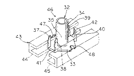
Fig. 5 is a perspective view corresponding to that
of Fig. 1, but showing a tee nut 46 according to a second
embodiment of the present invention. This tee nut 46
includes a number of elements which are common to those of
the aforementioned tee nut 31, and are denoted by similar
reference numerals, to omit redundant description.
Protrusions 47 and 48 are provided on a peripheral
edge of the tee nut 46 in opposite positions along a
radial direction which is perpendicular to that on which
the two pairs of pawls 37, 38, 39 and 40 respectively are
arranged opposite one another. These protrusions 47 and
48 project toward a second end of a shaft 32, similarly to
the pawls 37 to 40. Such protrusions 47 and 48 are formed
by inwardly crushing or bending parts of the outer
peripheral edge of a flange 33 from the exterior.
Consequently, notches having substantially semicircular
sections are left in the outer peripheral edge of the
flange 33.
Fig. 5 shows a feed track 43 in dashed phantom
lines. When the flange 33 is received in respective ones
of guide rails 44 and 45 which are provided in the feed
track 43, the protrusions 47 and 48 are located in the
guide rails 44 and 45 respectively. In this arrangement,
- 13 - 2107535
it is possible to substantially block any clearances
between the flange 33 and the guide rails 44 and 45 with
the protrusions 47 and 48.
Therefore, the flange 33 of the tee nut 46 is
prevented from upward movement in the guide rails 44 and
45, and this also prevents the flange 33 from overlapping
with a flange 33 of an adjacent tee nut 46. Even if the
protrusions 47 and 48 are in contact with the guide rails
44 and 45, it is possible to substantially reduce
frictional resistance therebetween when the protrusions 47
and 48 have pointed forward ends. This also contributes
to smooth movement of the tee nut 46 along the feed track
43.
Formation of the protrusions 47 and 48 is not
restricted to the aforementioned method, but the
protrusions 47 and 48 may alternatively be formed by
bending parts of the peripheral edge of the flange 33 or
pressing parts of the flange 33 in a direction
perpendicular to its surface direction.
Other features of the tee nut 46 shown in Fig. 5
differ from the tee nut 31 shown in Fig. 1, in addition to
the provision of the protrusions 47 and 48. First, the
shaft 32 of the tee nut 46 is longer than that of the tee
nut 31. This means that the length of the shaft 32 can be
changed in various ways as desired. Second, the indented
shapes or notches of the pawls 37 to 40 of the tee nut 46
are slightly different from those of the tee nut 31. This
means that the indented shapes or notches of the pawls 37
to 40 can be also changed in various ways.
Figs. 6 and 7, each corresponding to a part of Fig.
2, show third and fourth embodiments of the present
invention. These Figs. show modifications of pawls
respectively.
A pawl 49 shown in Fig. 6 is in the form of a hook
or barbed point. On the other hand, a pawl 50 shown in
Fig. 7 is neither indented nor hook-shaped, but has a
~'
2 1 07 535
- 14 -
straight shape. Thus, the shapes of the pawls are not
particularly restricted in the tee nut according to the
present invention.
Fig. 8 shows a fifth embodiment of the present
invention, in correspondence to a part of Fig. 4.
Referring to Fig. 8, elements corresponding to those shown
in Fig. 4 are denoted by similar reference numerals, to
omit redundant description.
Parts of an outer peripheral surface of a female
screw forming portion 35, which is provided on a shaft 32,
are inwardly crushed or indented so as to form two concave
indentations 51 and 52 with an angular space of 180, for
example. Such concave indentations 51 and 52 are formed
by holding prescribed parts of the female screw forming
portion 35 with a pair of proper tools and strongly
pressing these tools against the female screw forming
portion 35. The concave indentations 51 and 52 are
preferably formed in positions which are close to a flange
33. If the pair of indenting tools are applied at
positions far from the flange 33, the concave indentations
51 and 52 are hardly formed but instead the section of the
shaft 32 is easily flatly deformed. Further, the concave
indentations 51 and 52 are preferably formed at a stage
before formation of pawls 37 to 40 (Fig. 1) in the flange
33, so that such pawls 37 to 40 will not hinder
formation of the concave indentations 51 and 52 in the
vicinity of the flange 33.
Although the tee nut according to this embodiment
is provided with two concave indentations 51 and 52, the
number of such concave indentations is not restricted to
two. The inventive tee nut may alternatively be provided
with only one, or three or more concave indentations 51
and 52, for example.
Upon formation of the concave indentations 51 and
52, the female screw threading 36 is partially
irregularized, for example, by having a reduced inner
.~
~.
2 1 07 535
- 15 -
clearance diameter or an out-of-round shape or a varied
pitch at the locations of the indentations 51 and 52.
Thus, a bolt (not shown) which is fitted into the female
screw threading 36 cannot pass through such irregularized
portions 53 and 54 unless the bolt is relatively strongly
rotated. At this time, the thread may be partially
crushed in the irregularized portions. Consequently, the
bolt is locked in the state fitted into the female screw
threading 36, and is prevented from disengaging from the
tee nut.
While the present invention has been described with
reference to the embodiments shown in the drawings, the
flange is not restricted to an octagonal shape but may
have another shape so far as the pairs of pawls are
coupled with each other by linear sides.
Although the present invention has been described
and illustrated in detail, it is clearly understood that
the same is by way of illustration and example only and is
not to be taken by way of limitation, the scope of the
present invention being limited only by the terms of the
appended claims.